

Page 1
^ % Jjjk H ft ft -iWMM |tMi* ^ gpMMk mmtmAr mmm^ ''ftjj***
WH IXE** RODC3EF<S
DIVISION Of» EfwIEBSDN ELECTRIC
'»7S7 'BiAVt$ .f^OAD , .
" ^ r . LOUIS'/^Md '- n r " " : " '
READ ALL INSTRUCTIONS CAREFULLY, BEFORE INSTALLING OR OPERATING THIS THERMOSTAT
KEEP INSTRUCTION SHEET FOR FUTURE USE
This Light Duty Line Voltage Heating-Cooling Thermostat is
designed for controlling fan motors, circulator motors,
contactors, motor starters, valves, etc. To provide greater
room comfort, the thermostat is equipped v\/lth fixed
anticipators.
Two dial stops are supplied, which may be used for making a
maximum or minimum setting, a limited temperature range
or a locked dial setting. (See parts package).
The thermostat may be converted to horizontal mounting by
applying the adhesive backed horizontal dial over the
vertical dial. (See dial package).
The temperature may be set anywhere between 36° and 90° F
or 2° and 32°C by turning knob to the desired temperature
on the dial.
Positive off or system selection can be obtained by using a
switching sub-base.
SPECIFICATIONS
Switch Action: S.P.D.T.
(Heating, open on rise)
(Cooling, close on rise)
Range: 36 to 90° F. or 2° to 32° C.
CAUTION
________________
5° C, damage to the building and/or contents may result
due to freezing. This is possible due to factory calibration
tolerances, thermostat location and operating
characteristics of the heating equipment.
When thermostat is set below 40° F or
SELECTING LOCATION
The proper location of the room thermostat is most
important to insure that it will provide a comfortable home
temperature. Observe the following general rules when
selecting a location:
1. Locate it about 5 ft. above the floor.
2. Install it on a partitioning wall, not on an outside wall.
3. Never expose It to direct light from lamps, sun, fireplaces
or any temperature radiating equipment.
4. Avoid locations close to doors that lead outside, windows,
or adjoining outside walls.
— INSTRUCTIONS —
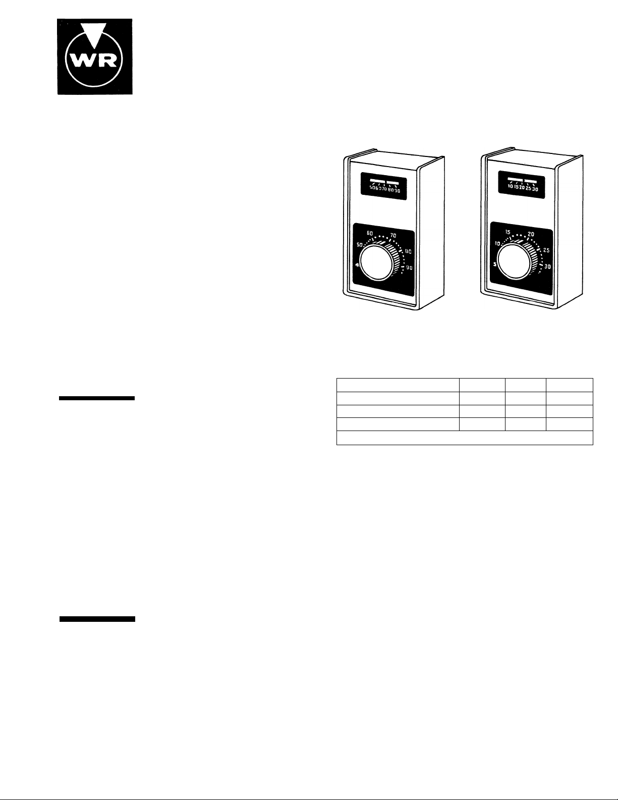
TYPE 1A10-SERIES
LIGHT DUTY LINE VOLTAGE
HEATING-COOLING
THERMOSTAT
DEGREES FAHRENHEIT
TYPE
Contact Structure: Snap Switch
Electrical Rating:
Voltage (A.C.)
Full Load Amps.
Locked Rotor Amps.
Resistive Amps.
Pilot Duty 125 VA
5. Avoid locations close to air registers, or in the direct path
of air from them.
6. Make sure there are no pipes or duct work in that part of
the wall chosen for the thermostat location.
7. Never locate It in a room that is warmer or cooler than the
rest of the home, such as the kitchen.
8. Avoid location with lack of air circulation, such as behind
doors or alcoves.
9. The living or dining room is normally a good location,
provided there is no cooking range or refrigerator on
opposite side of wall.
DEGREES CENTIGRADE
TYPE
120v. 240v.
8 4 4
48
24
8 8 8
277v.
24
INSTALLATION
CAUTION
__
To prevent electrical shock and/or
equipment damage, disconnect electric power to system,
at main fuse or circuit breaker box, until installation is
complete.
The thermostat may be mounted in any standard 3" x 2" or 4"
X 2" electrical outlet box. For ease of installation, use a deep
type box. USE COPPER CONDUCTORS ONLY.
Installation should be made as follows:
1. Cut field just long enough to reach wiring terminals with
thermostat held in palm of hand. (Appx. 6")
Printed in U.S.A.
2. Strip field wires 1/2" and make connections to wiring
terminals. Connect load (or loads) as shown on the
diagram for your application. (See wiring)
3. Remove thermostat cover by grasping top and bottom of
cover and pull straight out. Dress wiring into switch box
and secure thermostat to outlet box with mounting
screws.
NOTE: DO NOT PUSH OR DAMAGE THE KNOB
SENSING ELEMENT DURING INSTALLATION.
4. Install thermostat cover and turn knob to desired setting.
PART No. 37-3911
Replaces 37-3655-1, 37-3657, 37-3842, 37-3867
Page 2
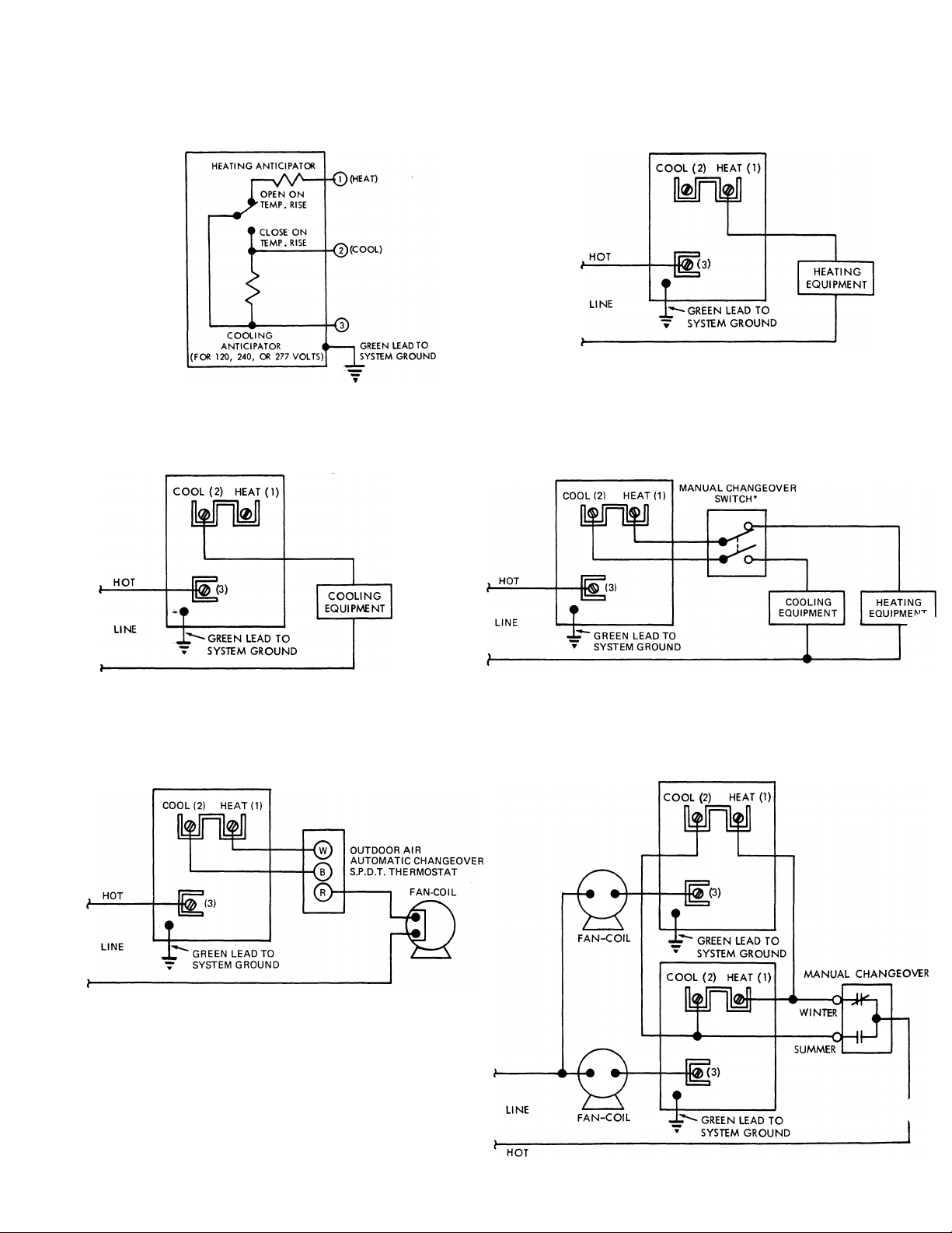
WIRING
NOTE: All wiring should be installed according to local and national electrical codes and ordinances.
INTERNAL SCHEMATIC OF 1A10 TYPICAL HOOK-UP FOR HEATING ONLY SYSTEM
TYPICAL HOOK-UP FOR COOLING ONLY SYSTEM
FAN COIL SYSTEM
HEATING-COOLING SYSTEM USING A
MANUAL CHANGEOVER SWITCH
■ POSITIVE OFF OR SYSTEM SELECTION CAN
BE OBTAINED BY USING A SWITCHING SUB-BASE.
HEATING-COOLING FAN-COIL SYSTEM
USING TWO OR MORE THERMOSTATS
Page 3

LOCKED DIAL SETTING OR LIMITED SETTING STOPS
The enclosed stops may be used to provide “LOCKED DIAL
SETTING” or “LIMITED SETTING”. Instructions for
installing the stops to perform either of these functions are
given below.
NOTE: Once stops are installed, they cannot be removed.
CAUTION
equipment damage, disconnect electric power to system,
at main fuse or circuit breaker box, until installation is
complete.
To prevent electrical shock and/or
INSTALLATION
PACKAGE CONTAINS:
2 — stops
2 — pins
STOP PIN
MAXIMUM LIMIT DIAL SETTING — By installing one Stop,
the maximum limit temperature may be set. (Example: Fig. A,
Max. Limit Setting 78° F or 26°C)
1. From Figure “A” select the hole at the outer edge of the
knob which corresponds to the maximum dial setting you
desire.
2. Rotate knob counter-clockwise to lowest setting. Remove
thermostat cover by grasping top and bottom and pull
straight out.
3. Position stop under knob so the hole in the stop and
selected hole in thermostat base are aligned. Insert pin
into aligned holes, but do not push pin completely down.
(Fig. ”D”)
4. Rotate knob clockwise to its newly selected maximum
setting. With the thermostat cover in place, this should
now be the maximum temperature setting you selected in
step #1. If setting is incorrect, the stop is still removable
and may be moved to another hole.
5. With stop installed in the correct hole, the pin can now be
seated down on the stop by pushing with the blade of a
screwdriver or gently tapping with a light object. Use care
not to hit the knob. The stop is now installed and cannot
be removed.
MINIMUM LIMIT DIAL SETTING — By Installing one Stop,
the minimum temperature may be set. (Example: Fig. B, Min.
Limit Setting 69°F or 21°C)
1. From Figure “B” select the hole at the outer edge of the
knob which corresponds to the minimum dial setting you
desire.
2. Rotate knob clockwise to highest setting. Remove
thermostat cover by grasping top and bottom and pull
straight out.
3. Position stop under knob so the hole in the stop and
selected hole in thermostat base are aligned, insert pin
into aligned holes but do not push pin completely down.
(Fig. D)
4. Rotate knob counter-clockwise to Its newly selected
minimum setting. With the thermostat cover in place, this
should now be the minimum temperature setting you
selected in step #1. If setting is incorrect, the stop is still
removable and may be moved to another hole.
5. With stop installed in the correct hole, the pin can now be
seated down on the stop by pushing with the blade of a
screwdriver or gently tapping with a light object. Use care
not to hit the knob.
LOCKED DIAL SETTING — By installing two Stops, the
Knob may be locked at a selected temperature (Fig. C).
1. Select the temperature setting at which the knob is to be
locked and locate the corresponding hole in fig. “A”
(Minimum 66°F or 19°C, Maximum 81°For 27°C). Install
the first stop as described In maximum limit dial setting
section.
2. Rotate the knob clockwise until It hits the first stop. Install
the second stop in the same manner In the second hole
down from first stop. (Example: Fig. C Knob setting is
locked at 72°F or 22°C and cannot be changed.)
MAX. DIAL SETTING STOP
MIN. DIAL SETTING STOP
LOCKED DIAL SETTING
 Loading...