

Page 1
CAUTION
WHITE-RODGERS
Operator: Save these instructions for future use!
FAILURE TO READ AND FOLLOW ALL INSTRUCTIONS CAREFULLY BEFORE
INSTALLING OR OPERATING THIS CONTROL COULD CAUSE PERSONAL
INJURY AND/OR PROPERTY DAMAGE.
These room thermostats have been designed for controlling cooling equipment operating on line voltage with
heavy electrical loads. They are suitable for operation of
unit coolers, room coolers, etc., or any similar refrigeration application requiring a heavy duty room thermostat.
Models are available with various ranges for meeting the
needs of almost any application.
THESE CONTROLS MUST BE INSTALLED BY A
QUALIFIED INSTALLER.
Do not exceed the specification ratings.
All wiring must conform to local and national electrical
codes and ordinances.
This control is a precision instrument, and should be
handled carefully. Rough handling or distorting components could cause the control to malfunction.
This control has been accurately calibrated at the factory.
Any attempt to calibrate this control will void the WhiteRodgers warranty.
The proper location of a heavy duty room thermostat is
very important to assure good performance. The following
general rules will help in determining the proper location:
1. Make sure that it is in a place where air circulates
around it freely. This is important.
2. Never install it on or near an outside wall.
3. Keep it away from windows or doors.
4. Don’t locate it too close to a strong light or any other
false source of heat such as direct sunlight, steam
lines, etc.
5. Mount it on a post or a partitioning wall, but make sure
that there are no pipes or duct work in that wall or
directly behind it.
6. If the electrical conduit leads into a cooler or a warmer
room, plug up the space around the wires in the conduit
with rock wool.
TYPE 151
ROOM THERMOSTAT
Cooling Service, External Dial
INSTALLATION INSTRUCTIONS
DESCRIPTION
W
H
I
T
E
-
R
S
O
R
D
E
G
90
70
80
50
60
40
PRECAUTIONS
To prevent electrical shock and/or equipment
damage, disconnect electric power to system, at
main fuse or circuit breaker box, until installation
is complete.
WARNING
Do not use on circuits exceeding specified voltages. Higher voltages will damage control and
could cause shock or fire hazard.
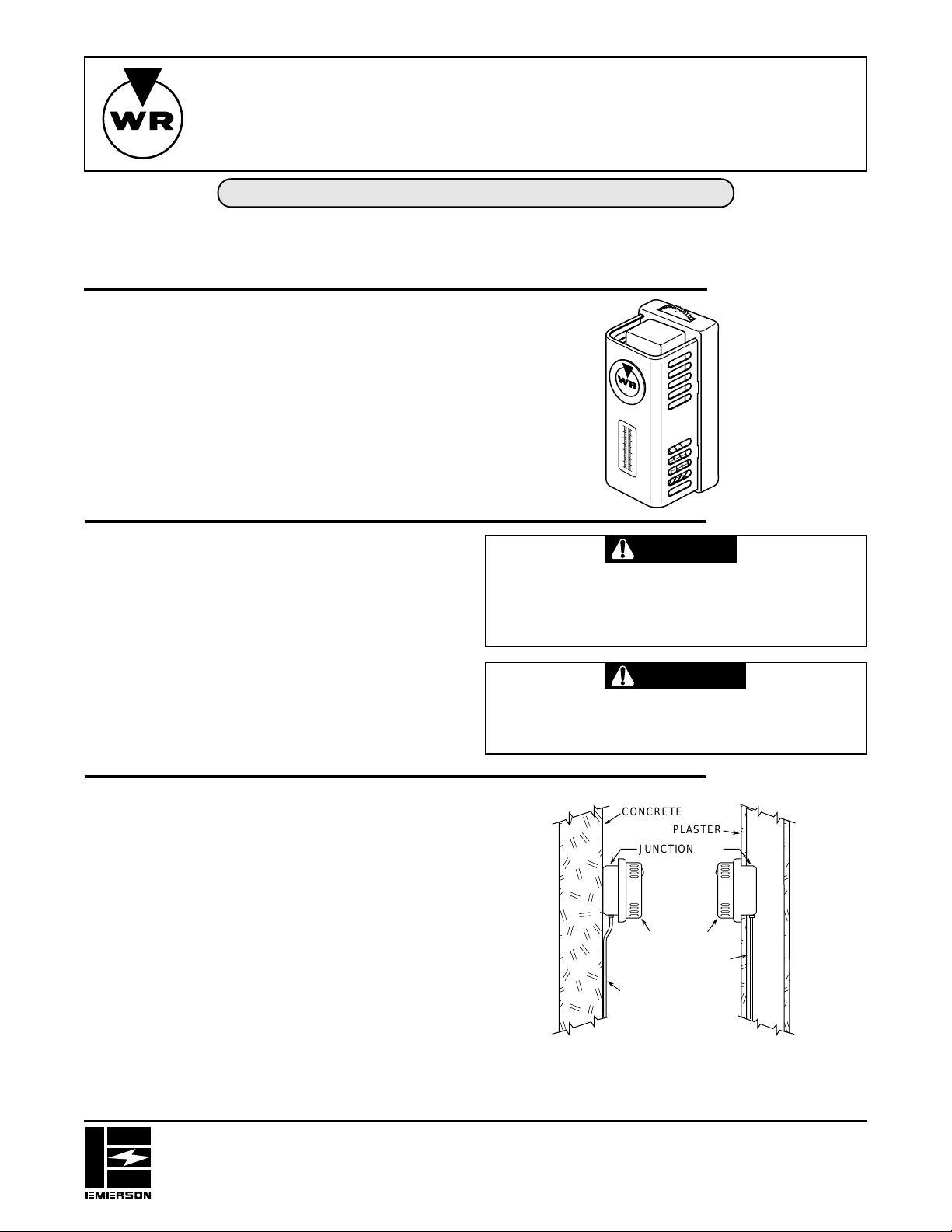
INSTALLATION
CONCRETE
PLASTER
JUNCTION BOX
THERMOSTAT
CONDUIT
INSIDE WALL
CONDUIT
ALONG WALL
WALL INSTALLATION
The mounting plate for this thermostat has two
5
holes 3
/16”apart for attaching the control on a
standard switch box.
Figure 1
WHITE-RODGERS DIVISION
EMERSON ELECTRIC CO.
9797 REAVIS RD., ST. LOUIS, MO. 63123
(314) 577-1300, FAX (314) 577-1517
9999 HWY. 48, MARKHAM, ONT. L3P 3J3
(905) 475-4653, FAX (905) 475-4625
Printed in U.S.A.
PART NO. 37-1118B
Replaces 37-1118
9548
Page 2

INSTALLATION CONT.
70
60
80
INDICATING
LINE
IMPORTANT
When control is located where ambient temperature is
below freezing, choose a control location far enough
away from doors and windows so that moisture will not
condense on control.
If the thermostat is used with unit coolers, the following
suggestions may help. (See Fig. 2).
1. Position “A” is good if it is sufficiently close to the unit
cooler so that the return air to the cooler flows over the
thermostat.
2. Position “B” is good if it is not necessary to make
frequent adjustments of the dial setting.
3. Position “C” is all right if it is sufficiently far from the
cooler that air flowing over the thermostat is not much
above the average room temperature.
4. In general, position “D” is not advisable because the
post may prevent air from circulating over the thermostat.
CEILING
POST
UNIT
B
D
C
RETURN AIR
FLOOR
Figure 2
PARTITION
WALL OR POST
DIRECTLY
BEHIND UNIT
A
WIRING
All wiring should be done in accordance with local and national electrical codes and ordinances.
If the manufacturer of the cooling equipment has supplied a wiring diagram, follow the manufacturer’s recommendations. The following diagrams show the general use of these controls.
TEMPERATURE
CONTROL
TO LINE SWITCH
AND POWER SUPPLY
HOT
GND
Circuit showing temperature control to open and
close refrigerant valve. Suction pressure control
starts and stops compressor through motor starter.
HIGH SIDE
PRESSURE CONTROL
(IF USED)
MOTOR
STARTER
Circuit showing temperature control controlling compressor directly.
TO LINE SWITCH
AND POWER SUPPLY
HIGH SIDE
PRESSURE
CONTROL
SUCTION
PRESSURE
CONTROL
TEMPERATURE
CONTROL
SOLENOID
REFRIGERANT
VALVE
SETTING THE DIAL
To set the dial, simply move it so that the indicating line on
the case points to the temperature at which the contacts
are to open as the temperature drops.
2
Page 3

WHITE-RODGERS
Utilisateur: conservez ces instructions pour vous y référer au besoin!
SI VOUS NE LISEZ PAS ATTENTIVEMENT CES INSTRUCTIONS AVANT
D’INSTALLER ET D’UTILISER LA COMMANDE, VOUS RISQUEZ DE CAUSER
DES BLESSURES ET DES DOMMAGES MATÉRIELS.
Ces thermostat d’ambiance ont été conçus spécialement pour
commander des installations de refroidissement fonctionnant
avec des charges électriques élevées à la tension du réseau. Ils
conviennent à l’utilisation de refroidisseurs d’air, de blocs
refroidisseurs de pièces, etc., ou de tout appareil semblable
exigeant un thermostat d’ambiance robuste.
Plusieurs modèles sont disponibles avec des plages variées
permettant d’adapter la commande à presque toutes les
applications possibles.
LA COMMANDE DOIT ÊTRE INSTALLÉE PAR UN TECHNICIEN QUALIFIÉ.
Ne dépassez pas les charges nominales.
Tout le câblage doit être conforme aux codes et règlements
locaux et nationaux qui régissent les installations électriques.
Cette commande est un instrument de précision qui doit être
manipulé avec soin. Elle peut se détraquer si elle est manipulée
de façon négligente ou si des composantes sont déformées.
La commande a été calibrée avec précision lors de la fabrication.
Toute tentative de calibrer l’appareil annulera la garantie de
White-Rodgers.
TYPE 151
THERMOSTAT D’AMBIANCE
Pour refroidissement, à cadran extérieur
INSTALLATION INSTRUCTIONS
DESCRIPTION
W
H
I
T
E
-
R
S
O
R
D
E
G
90
70
80
50
60
40
PRÉCAUTIONS
ATTENTION
Afin de prévenir les chocs électriques et les dommages
matériels pendant l’installation, coupez l’alimentation
électrique au panneau de distribution principal.
AVERTISSEMENT
N’installez pas cet appareil sur des circuits qui dépassent la tension nominale. Une tension trop élevée peut
endommager la commande et poser des risques de
chocs électriques et d’incendie.
Le choix d’un bon emplacement pour un thermostat d’ambiance
robuste est essentiel à son bon rendement. Les règles générales
suivantes aideront à déterminer un bon emplacement :
1. S’assurer que l’air circule librement autour du thermostat .
Ceci est important.
2. Ne jamais installer le thermostat sur un mur extérieur ou à
proximité d’un tel mur.
3. Installer le thermostat à l’écart des portes et fenêtres.
4. Ne jamais installer le thermostat près d’une source ponctuelle
de chaleur, comme les rayons du soleil, des tuyaux de
vapeur, etc.
5. Installer le thermostat sur un poteau ou une cloison intérieure
en s’assurant d’abord qu’il ne se trouve pas directement
devant des tuyaux ou des conduits.
6. Si le conduit électrique traverse un mur vers une pièce plus
chaude ou plus fraîche, placer de la laine minérale autour
des fils dans le conduit.
WHITE-RODGERS DIVISION
EMERSON ELECTRIC CO.
9797 REAVIS RD., ST. LOUIS, MO. 63123
(314) 577-1300, Télécopieur (314) 577-1517
9999 HWY. 48, MARKHAM, ONT. L3P 3J3
(905) 475-4653, Télécopieur (905) 475-4625
Imprimé aux États-Unis
INSTALLATION
CONCRETE
BÉTON
RACCORDEMENT
CONDUIT LE
CONDUIT
LONG DU MUR
ALONG WALL
INSTALLATION MURALE
WALL INSTALLATION
La plaque de montage du thermostat est dotée de
The mounting plate for this thermostat has two
5
deux trous séparés par 3-5/16”, qui servent à fixer la
/16”apart for attaching the control on a
holes 3
standard switch box.
commande sur une boîte de raccordement ordinaire.
PLÂTRE
PLASTER
BOÎTE DE
JUNCTION BOX
THERMOSTAT
CONDUIT
CONDUIT
DANS LE MUR
INSIDE WALL
Figure 1
NO DE PIÈCE 37-1118B
Remplace 37-1118
9548
Page 4

INSTALLATION
IMPORTANT
Lorsque le régulateur est installé dans un endroit où la
température ambiante est inférieure au point de
congélation, choisir un emplacement qui est assez loin
des portes et fenêtres pour que l’humidité ne condense
pas sur la commande.
Lorsque le thermostat est utilisé avec des refroidisseurs, les
conseils suivants peuvent s’avérer utiles (voir la fig. 2) :
1. L’emplacement A est convenable s’il est assez près du
refroidisseur pour que l’air de retour circule autour du
thermostat.
2. L’emplacement B est convenable si le point de consigne ne
doit pas être réglé souvent.
3. L’emplacement C est convenable s’il est assez éloigné du
refroidisseur pour que l’air qui circule autour du thermostat
ne soit pas beaucoup plus chaud que la température moyenne
de l’air dans la pièce.
4. En général, l’emplacement D n’est pas recommandé parce
que le poteau peut empêcher l’air de circuler autour du
thermostat.
CÂBLAGE
Tout le câblage doit être conforme aux codes et règlements locaux et nationaux
qui régissent les installations électriques.
PLAFOND
POTEAU CLOISON
REFROIDISSEUR
D
C
AIR DE RETOUR
PLANCHER
B
OU POTEAU SITUÉ
DIRECTEMENT
DERRIÈRE LE
REFROIDISSEUR
A
Fig. 2
Si le fabricant de l’équipement de réfrigération recommande un schéma de câblage, alors veuillez vous y référer. Les schémas
suivants correspondent à un usage typique du régulateur.
Temperature
RÉGULATEUR
control
SOUS
VERS
TENSION
To line switch
L’INTERRUPTEUR
and power supply
ET L’ALIMENTATION
HOT
GND
MALT
Circuit du régulateur employé pour ouvrir et fermer
High side
MANOSTAT DU
pressure control
CÔTÉ ÉLEVÉ
(if used)
(SI EMPLOYÉ)
Circuit du régulateur contrôlant
directement un compresseur.
VERS L’INTERRUPTEUR
To line switch
ET L’ALIMENTATION
and power supply
Temperature
RÉGULATEUR
control
la vanne du réfrigérant. Le manostat d’aspiration
met le compresseur en marche et hors marche par
l’intermédiaire du démarreur du moteur.
DÉMARREUR
DU MOTEUR
Motor
starter
MANOSTAT
High side
DU CÔTÉ
pressure
ÉLEVÉ
control
ÉLECTROVANNE
DU RÉFRIGÉRANT
Suction
MANOSTAT
pressure
control
D’ASPIRATION
Solenoid
refrigerant
valve
MODE D’EMPLOI
Pour régler le thermostat, simplement déplacer le cadran pour
que la ligne indicatrice du boîtier soit alignée sur la température
à laquelle le circuit doit être ouvert suite à une baisse de la
température.
LIGNE
INDICATING
INDICATRICE
LINE
80
70
60
2
 Loading...