

Page 1
WHITE-RODGERS
Operator: Save these instructions for future use!
FAILURE TO READ AND FOLLOW ALL INSTRUCTIONS CAREFULLY BEFORE
INSTALLING OR OPERATING THIS CONTROL COULD CAUSE PERSONAL
INJURY AND/OR PROPERTY DAMAGE.
These controls are designed for use on hot water heating
installations. They have open-on-rise switch action and
are available with either fixed or adjustable differential.
Models are available with either horizontal or vertical well.
Some of these models also have excess capillary stored
within the enclosure, permitting them to be used with wells
having either a standard or extended shank.
Another model, ideal for replacement purposes, has a
slotted case and excess capillary stored within the enclosure. This control can be used with either a standard or
extended shank well, on either horizontal or vertical well
installations.
THESE CONTROLS MUST BE INSTALLED BY A
QUALIFIED INSTALLER.
Do not exceed the specification ratings.
All wiring must conform to local and national electrical
codes and ordinances.
This control is a precision instrument, and should be
handled carefully. Rough handling or distorting components could cause the control to malfunction.
This control has been accurately calibrated at the factory.
Any attempt to calibrate this control will void the WhiteRodgers warranty.
WARNING
Do not use on circuits exceeding specified
voltages. Higher voltages will damage control
and could cause shock or fire hazard.
11B18
HOT WATER CONTROL
Open on Rise, Well-Immersion
INSTALLATION INSTRUCTIONS
DESCRIPTION
PRECAUTIONS
CAUTION
Label all wires prior to disconnection when servicing controls. Wiring errors can cause improper and dangerous operation.
Following installation or replacement, follow
appliance manufacturer’s recommended installation and/or service instructions to insure proper
operation.
CAUTION
To prevent electrical shock and/or equipment
damage, disconnect electric power to system, at
main fuse or circuit breaker box, until installation
is complete.
Shut off main gas to heating system until installation is complete.
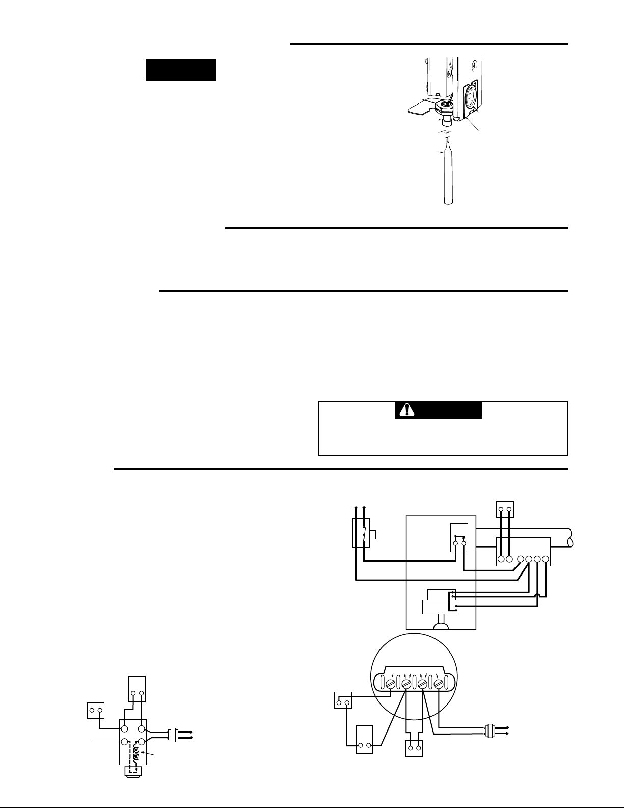
Convertible controls have a Knockout Plate on back of
case (secured by Hex Nut on Horizontal models, and by
Knockout Plug on Vertical models). To convert from
Horizontal to Vertical:
1. Remove control cover. Then remove bottom knockout.
2. Remove Hex Nut (inside control) from Well Mounting
Stem. (To loosen, hold Hex Nut inside while turning
Hex Nut on back of control counterclockwise.)
WHITE-RODGERS DIVISION
EMERSON ELECTRIC CO.
9797 REAVIS RD., ST. LOUIS, MO. 63123
(314) 577-1300, FAX (314) 577-1517
9999 HWY. 48, MARKHAM, ONT. L3P 3J3
(905) 475-4653, FAX (905) 475-4625
Printed in U.S.A.
CONVERTIBLE CONTROLS
3. Pull Well Mounting Stem away from case and remove
Knockout Plate.
4. Swing capillary down through slot into bottom knockout.
5. Secure Knockout Plate to back of case by using
Knockout Plug provided in envelope.
6. Insert Well Mounting Stem into bottom knockout and
tighten Hex Nut (inside control) securely.
PART NO. 37-2068B
Replaces 37-2068A & 37-9199
9545
Page 2
CONVERTIBLE CONTROLS CONT.
NOTE
To convert from Vertical to Horizontal model, remove
Knockout Plug and Plate. Remove Hex Nut (inside control) and swing capillary upward into back knockout. Place
Knockout Plate beneath Hex Nut on back of control and
tighten Hex Nut (inside control). If bottom knockout is not
used for wiring, insert Knockout Plug.
EXTENDING CAPILLARY
Some controls have excess stored capillary which may be
extended for use with an extended shank well. Use reasonable care when straightening and forming the capillary.
INSTALLATION
If the boiler manufacturer recommends a control location,
follow such recommendations. If none is offered, the
following information gives suggested locations.
When used for high limit service, the control should be
installed in the riser close to the boiler, or in a boiler
tapping that is near the top or hottest section of the boiler.
If the boiler is also used to heat domestic hot water, make
sure that the high limit control is not located in the section
of the boiler that contains the heat exchanger or piping for
domestic hot water.
When used for low limit or operator service, the control
should be located near that section of the boiler that
HEX NUT
MOUNTING STEM
CAPILLARY
BULB
KNOCKOUT PLUG
KNOCKOUT PLATE
Convertible Control converted to Vertical Model.
With the capillary fully extended, the bulb should slide all
the way to the end of the well.
contains the heat exchanger or piping for domestic hot
water.
To remove the well from the control, loosen the set screw
in the large nut, then slide the well off to expose the bulb.
Screw the well into the proper tapping. Slide the bulb back
into the well, making sure that the bulb enters the well as
far as it will go and tighten the set screw.
CAUTION
Do not dent or bend the bulb as this will prevent
it from fitting into the well properly.
WIRING
All wiring should be done in accordance with local and national electrical codes and ordinances.
If the boiler or burner manufacturer recommends a wiring
diagram, then follow such recommendations.
If none is offered, these diagrams show suggested circuits.
HIGH
LIMIT
Used as high limit control
THERMOSTAT
SILENT KNIGHT
GAS VALVE
AUX
2 3
TH TR
1 4
with Silent Knight gas
valve with plug-in pilot
TRANSFORMER
COIL
PLUG-IN
PILOT
TO
LINE
LINE
GND HOT
Used as high limit
control with
oil burner control
THERMOSTAT
LIMIT
CONTROL
2
FUSED
LINE
SWITCH
THERM PILOT
INTERMITTENT IGNITION
OIL BURNER CONTROL
LIMIT
CONTROL
TRANS
MOTOR
DIAPHRAGM
GAS VALVE
TRANS
AUTOMATIC
IF AUTOMATIC PILOT IS NOT USED,
CONNECT A JUMPER BETWEEN
PILOT
THE PILOT TERMINALS
THERMOSTAT
STACK
1
4
2
T
3
T
Used as high limit
control with
diaphragm gas valve
TRANSFORMER
TO
LINE
Page 3

SETTING THE CONTROL
CONTROLS WITH ADJUSTABLE DIFFERENTIAL
The movable indicator points to the temperature at which
the contacts open. The fixed indicator points to the temperature at which the contacts close. The difference
between these two indicators is the differential.
To set the control:
1. Use a screwdriver in the adjusting slot (A) on the front
of the control to turn the dial so that the fixed indicator
(B) points to the temperature at which the contacts will
close.
2. Turn the differential adjusting screw (C) until the
movable indicator (D) points to the temperature at
which the contacts will open.
“B” Fixed indicator
“F” Stop tab
“A” Adjusting
slot
ADJUSTABLE DIFFERENTIAL
(cut-in point)
“C” Differential adjusting
screw
“D” Movable indicator
(cut-out point)
“E” Stop screw
CONTROLS WITH A FIXED DIFFERENTIAL
The indicator (B) points to the temperature at which the
contacts open.
To set the control:
Use a screwdriver in the adjusting slot (A) on the front
of the control to rotate dial until the desired temperature at which the contacts will open is positioned
directly under the indicator (B).
CONTROLS WITH ADJUSTABLE STOPS
CAUTION
Setting stop higher than control being replaced
could cause personal injury and/or property damage.
1. Loosen stop screw (E) with enclosed wrench.
2. Set dial to original equipment manufacturer's specification.
3. Without moving the dial, move stop tab (F) against
indicator.
4. Retighten stop screw (E).
“F” Stop tab
“E” Stop screw
“A” Adjusting
FIXED DIFFERENTIAL
“B” Fixed
indicator
slot
3
Page 4

WHITE-RODGERS
Utilisateur: conservez ces instructions pour vous y référer au besoin!
SI VOUS NE LISEZ PAS ATTENTIVEMENT CES INSTRUCTIONS AVANT
D’INSTALLER ET D’UTILISER LA COMMANDE, VOUS RISQUEZ DE CAUSER
DES BLESSURES ET DES DOMMAGES MATÉRIELS.
Cette commande a été conçue pour servir avec un
système de chauffage à eau chaude. Elle est dotée d’un
commutateur ouvert sur hausse. Le différentiel peut être
fixe ou réglable, selon le modèle.
Ils existe des modèles qui conviennent aux gaines
verticales et horizontales. Certains des modèles sont
aussi dotés dans le boîtier d’un surplus de capillaire qui
permet de les utiliser avec une gaine normale ou longue.
Un autre modèle, idéal comme remplacement, est doté
d’un boîtier à rainure et d’un surplus de capillaire. Il peut
ainsi servir avec une gaine normale ou longue montée
verticalement ou horizontalement.
11B18
COMMANDE D’EAU CHAUDE
Ouverture sur hausse, avec gaine
INSTALLATION INSTRUCTIONS
DESCRIPTION
LA PRÉSENTE COMMANDE DOIT ÊTRE INSTALLÉE
PAR UN TECHNICIEN QUALIFIÉ.
Ne dépassez pas les charges nominales.
Tout le câblage doit être conforme aux codes et règlements
locaux et nationaux qui régissent les installations
électriques.
Cette commande est un instrument de précision qui doit
être manipulé avec soin. Elle peut se détraquer si elle est
manipulée de façon négligente ou si des composantes
sont déformées.
La commande a été calibrée avec précision lors de la
fabrication. Toute tentative de calibrer l’appareil annulera
la garantie de White-Rodgers.
AVERTISSEMENT
N’installez pas cet appareil sur des circuits qui
dépassent la tension nominale. Une tension trop
élevée peut endommager la commande et poser
des risques de chocs électriques et d’incendie.
Les commandes convertibles sont dotées à l’arrière
d’une plaque de conversion (tenue par un écrou hexagonal
sur les modèles horizontaux et par un bouchon de
conversion sur les modèles verticaux). Pour convertir la
commande de l’horizontale à la verticale :
1. Retirer le couvercle de la commande. Retirer ensuite
la plaque inférieure.
2. Retirer l’écrou hexagonal (à l’intérieur de la commande)
de la tige de montage de la gaine. (Pour desserrer
l’écrou, le tenir tout en tournant à gauche l’écrou
hexagonal qui se trouve à l’arrière de la commande).
WHITE-RODGERS DIVISION
EMERSON ELECTRIC CO.
9797 REAVIS RD., ST. LOUIS, MO. 63123
(314) 577-1300, FAX (314) 577-1517
9999 HWY. 48, MARKHAM, ONT. L3P 3J3
(905) 475-4653, FAX (905) 475-4625
Imprimé aux É.-U.A.
PRÉCAUTIONS
ATTENTION
Prenez soin d’identifier les fils avant de débrancher
ou de réviser la commande. Les erreurs de
raccordement peuvent entraîner un fonctionnement incorrect ou dangereux de la commande.
Pour assurer le bon fonctionnement de la
commande après l’avoir installée, veuillez suivre
les directives d’installation ou de révision du
fabricant de l’équipement.
ATTENTION
Afin de prévenir les chocs électriques et les
dommages matériels pendant l’installation,
coupez l’alimentation électrique au panneau de
distribution principal.
Coupez le gaz qui alimente le système de
chauffage pendant toute la durée de l’installation.
COMMANDES CONVERTIBLES
3. Dégager la tige de montage de la gaine et retirer la
plaque de conversion.
4. Glisser le capillaire dans la rainure jusqu’à la plaque
inférieure.
5. Fixer la plaque de conversion à l’arrière de la commande
à l’aide du bouchon de conversion qui se trouve dans
l’enveloppe.
6. Introduire la tige de montage de la gaine dans la
plaque inférieure et serrer solidement l’écrou hexagonal
(à l’intérieur de la commande).
PIÈCE No 37-2068B
Remplace 37-2068A & 37-9199
9545
Page 5

COMMANDES CONVERTIBLES (suite)
NOTE
Pour convertir la commande de la verticale à l’horizontale,
retirer d’abord le bouchon et la plaque de conversion.
Retirer l’écrou hexagonal (à l’intérieur de la commande)
et glisser le capillaire dans la rainure jusqu’à la plaque
arrière. Placer la plaque de conversion sous l’écrou
hexagonal à l’arrière de la commande et serrer l’écrou
hexagonal (à l’intérieur de la commande). Si l’ouverture
de la plaque inférieure ne sert pas au câblage,y poser le
bouchon de conversion.
EXTENSION DU CAPILLAIRE
Certaines commandes ont un surplus de capillaire qui
peut être allongé afin de servir avec une gaine allongée.
Procéder soigneusement pour redresser et former le
capillaire.
INSTALLATION
Si un emplacement de la commande est recommandé par
le fabricant de la chaudière, alors veuillez vous y conformer.
Si aucun emplacement n’est suggéré, veuillez suivre les
conseils suivants.
Lorsque la commande est utilisée comme limiteur à
maximum, elle doit être installée près de la chaudière,
sur la colonne montante, ou dans une ouverture taraudée
qui est située dans la partie supérieure ou dans la section
la plus chaude de la chaudière. Si la chaudière sert aussi
pour l’eau chaude domestique, s’assurer que le limiteur à
maximum n’est pas installé dans la partie de la chaudière
où se trouvent l’échangeur de chaleur ou les canalisations
d’eau chaude domestique.
Lorsque la commande sert de limiteur à minimum ou
d’actionneur, elle doit alors être installée dans la partie
ÉCROU HEXAGONAL
TIGE DE MONTAGE
CAPILLAIRE
CAPTEUR
BOUCHON DE
CONVERSION
PLAQUE DE
CONVERSION
Commande convertie en modèle vertical.
Une fois le capillaire complètement allong, le capteur doit
glisser jusqu’au fond de la gaine.
de la chaudière où se trouvent l’échangeur de chaleur ou
les canalisations d’eau chaude domestique.
Pour séparer la gaine de la commande, desserrer d’abord
la vis de réglage du gros écrou, puis glisser la gaine pour
exposer le capteur. Visser la gaine dans l’ouverture
taraudée qui convient. Réintroduire ensuite le capteur
dans la gaine en prenant soin qu’il soit bien au fond. Serrer
la vis de réglage.
ATTENTION
Ne pas plier ou bosser le capteur, car il serait
alors impossible de l’introduire correctement dans
la gaine.
CÂBLAGE
Tout le câblage doit être conforme aux codes et règlements
locaux et nationaux qui régissent les installations
électriques.
Si le fabricant de la chaudière ou du brûleur recommande
un schéma de câblage, alors veuillez vous y référer.
Dans le cas contraire, voici quelques schémas de circuits
recommandés.
HIGH
LIMITEUR À
LIMIT
THERMOSTAT
THERMOSTAT
ROBINET À GAZ
SILENT KNIGHT
SILENT KNIGHT
GAS VALVE
MAXIMUM
AUX
2 3
TH TR
1 4
Utilisée comme limiteur à
Used as high limit control
maximum avec robinet à
gaz Silent Knight à
with Silent Knight gas
veilleuse enfichable
valve with plug-in pilot
TRANSFORMATEUR
TRANSFORMER
BOBINE
COIL
VEILLEUSE
PLUG-IN
ENFICHABLE
PILOT
TO
SECTEUR
LINE
SECTEUR
LINE
NEUTRE
SOUS TENSION
GND HOT
COMMUTATEUR
DE SECTEUR
À FUSIBLE
FUSED
LINE
SWITCH
Utilisée comme
limiteur à maximum
Used as high limit
avec commande de
control with
brûleur à mazout
oil burner control
THERMOSTAT
LIMIT
LIMITEUR
CONTROL
2
COMMANDE DE BRÛLEUR À
INTERMITTENT IGNITION
MAZOUT À ALLUMAGE
OIL BURNER CONTROL
INTERMITTENT
LIMIT
CONTROL
LIMITEUR
TRANS
MOTEUR
MOTOR
ROBINET À GAZ
DIAPHRAGM
À MEMBRANE
GAS VALVE
VEILLEUSE
AUTOMATIC
AUTOMATIQUE
PILOT
TRANS
THERM PILOT
THERMOSTAT
1
2
T
T
Utilisée comme limiteur
Used as high limit
à maximum avec robinet
control with
à gaz à membrane
diaphragm gas valve
TRANSFORMATEUR
TRANSFORMER
SI UNE VEILLEUSE AUTOMATIQUE N’EST PAS
IF AUTOMATIC PILOT IS NOT USED,
UTILISÉE, RACCORDER LES DEUX BORNES DE
CONNECT A JUMPER BETWEEN
LA VEILLEUSE À L’AIDE D’UN CAVALIER.
THE PILOT TERMINALS
TO
SECTEUR
LINE
CHEMINÉE
4
3
STACK
Page 6

RÉGLAGE DE LA COMMANDE
COMMANDES À DIFFÉRENTIEL RÉGLABLE
L’indicateur mobile donne la température à laquelle les
contacts seront ouverts. L’indicateur fixe donne la température à laquelle les contacts seront fermés. La différence
entre les deux indicateurs représente le différentiel.
Pour régler la commande :
1. Introduire la pointe d’un tournevis dans la fente de
réglage (A) qui se trouve à l’avant de la commande.
Tourner le cadran pour que l’indicateur fixe (B) indique
la température à laquelle les contacts devront être
fermés.
2. Tourner la vis de réglage du différentiel (C) jusqu’à ce
que l’indicateur mobile (D) indique la température à
laquelle les contacts devront être ouverts.
B INDICATEUR FIXE
F BUTÉE
A FENTE DE
RÉGLAGE
DIFFÉRENTIEL RÉGLABLE
(POINT D’ENCLENCHEMENT)
C VIS DE RÉGLAGE
DU DIFFÉRENTIEL
D INDICATEUR MOBILE
(POINT DE DÉCLENCHEMENT)
E VIS DE BUTÉE
COMMANDES À DIFFÉRENTIEL FIXE
L’indicateur (B) donne la température à laquelle les
contacts seront ouverts.
Pour régler la commande :
Introduire la pointe d’un tournevis dans la fente de
réglage (A) qui se trouve à l’avant de la commande.
Tourner le cadran pour que la température à laquelle
les contacts devront être ouverts se trouve directement
sous l’indicateur (B).
COMMANDES À BUTÉES RÉGLABLES
ATTENTION
Il y a un risque de blessures et de dommages
matériels si la butée est réglée à un point de
consigne plus élevé que celle de la commande
qui est remplacée.
1. Desserrer la vis de butée (E) à l’aide de la clé fournie.
2. Régler le cadran selon les recommandations du
fabricant de l’équipement.
3. En prenant soin de ne pas déplacer le cadran, accoter
la butée (F) contre l’indicateur.
4. Serrer à nouveau la vis de butée (E).
F BUTÉE
E VIS DE BUTÉE
B INDICATEUR FIXE
A FENTE DE
DIFFÉRENTIEL FIXE
(POINT D’ENCLENCHEMENT)
RÉGLAGE
3
 Loading...