

Page 1
TYPE 1145
WHITE-RODGERS
Operator: Save these instructions for future use!
FAILURE TO READ AND FOLLOW ALL INSTRUCTIONS CAREFULLY
BEFORE INSTALLING OR OPERATING THIS CONTROL COULD CAUSE
PERSONAL INJURY AND/OR PROPERTY DAMAGE.
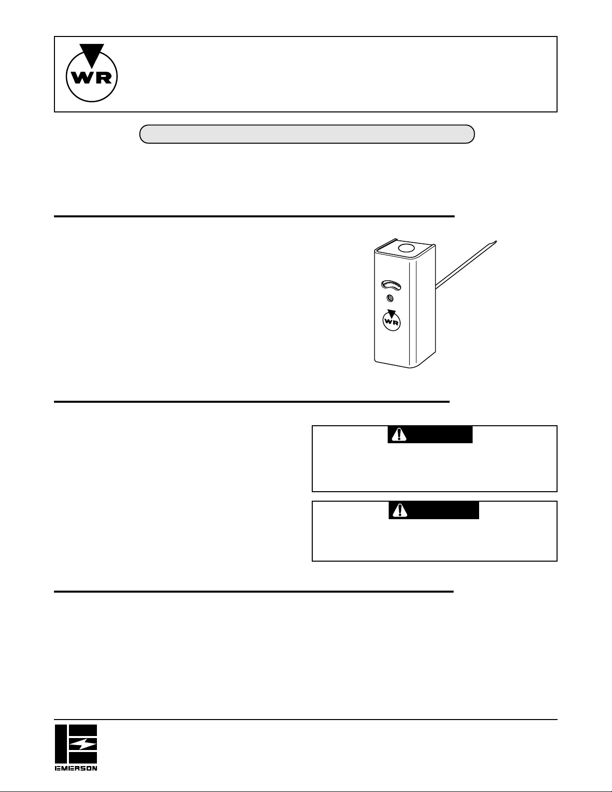
This control, designed for use on hot water heating systems,
has an element that is immersed directly into the boiler water.
This feature gives unusual speed of response to rapid changes
of water temperature thereby preventing thermal lag.
It has open on rise contact action. This control may be used as
a high limit or as a low limit control.
These controls have special contacts which are suitable for use
on low voltage and millivolt (thermocouple generator type)
circuits as well as line voltage gas valve and motor loads.
HOT WATER CONTROL
Direct Immersion - Adjustable Differential
INST ALLA TION INSTRUCTIONS
DESCRIPTION
THESE CONTROLS MUST BE INSTALLED BY A QUALIFIED
INSTALLER.
Do not exceed the specification ratings.
All wiring must conform to local and national electrical codes and
ordinances.
This control is a precision instrument, and should be handled
carefully. Rough handling or distorting components could cause
the control to malfunction.
This control has been accurately calibrated at the factory. Any
attempt to calibrate this control will void the White-Rodgers
warranty.
If the boiler manufacturer recommends a control location, then
follow such recommendations. If none are offered, the following
information shows suggested locations.
For high limit service, the control should be located in the hottest
part of the boiler. This is usually near the top of the boiler. A high
limit control should not be in the same section of the boiler that
contains the heater or the pipes that heat domestic hot water.
PRECAUTIONS
CAUTION
To prevent electrical shock and/or equipment damage,
disconnect electric power to system at main fuse or
circuit breaker box until installation is complete.
WARNING
Do not use on circuits exceeding specified voltage.
Higher voltage will damage control and could cause
shock or fire hazard.
INSTALLATION
For low limit or operating service, the control should be so
located, that it responds to the temperature of that section of the
boiler that heats domestic hot water.
When tightening the control into the boiler, care should be taken
to apply all leverage on the hexagonal nut so as not to injure the
diaphragm or control mechanisms.
WHITE-RODGERS DIVISION
EMERSON ELECTRIC CO.
9797 REAVIS RD., ST. LOUIS, MO. 63123
(314) 577-1300, FAX (314) 577-1517
9999 HWY. 48, MARKHAM, ONT. L3P 3J3
(905) 475-4653, FAX (905) 475-4625
Printed in U.S.A.
PART NO. 37-0577E
Replaces 37-0577-3 & 37-9157
9548
Page 2
WIRING
All wiring should be done in accordance with local and national electrical codes and ordinances.
If the boiler or burner manufacturer recommends a wiring
diagram, then follow such recommendations. If none is offered,
this diagram shows a suggested circuit.
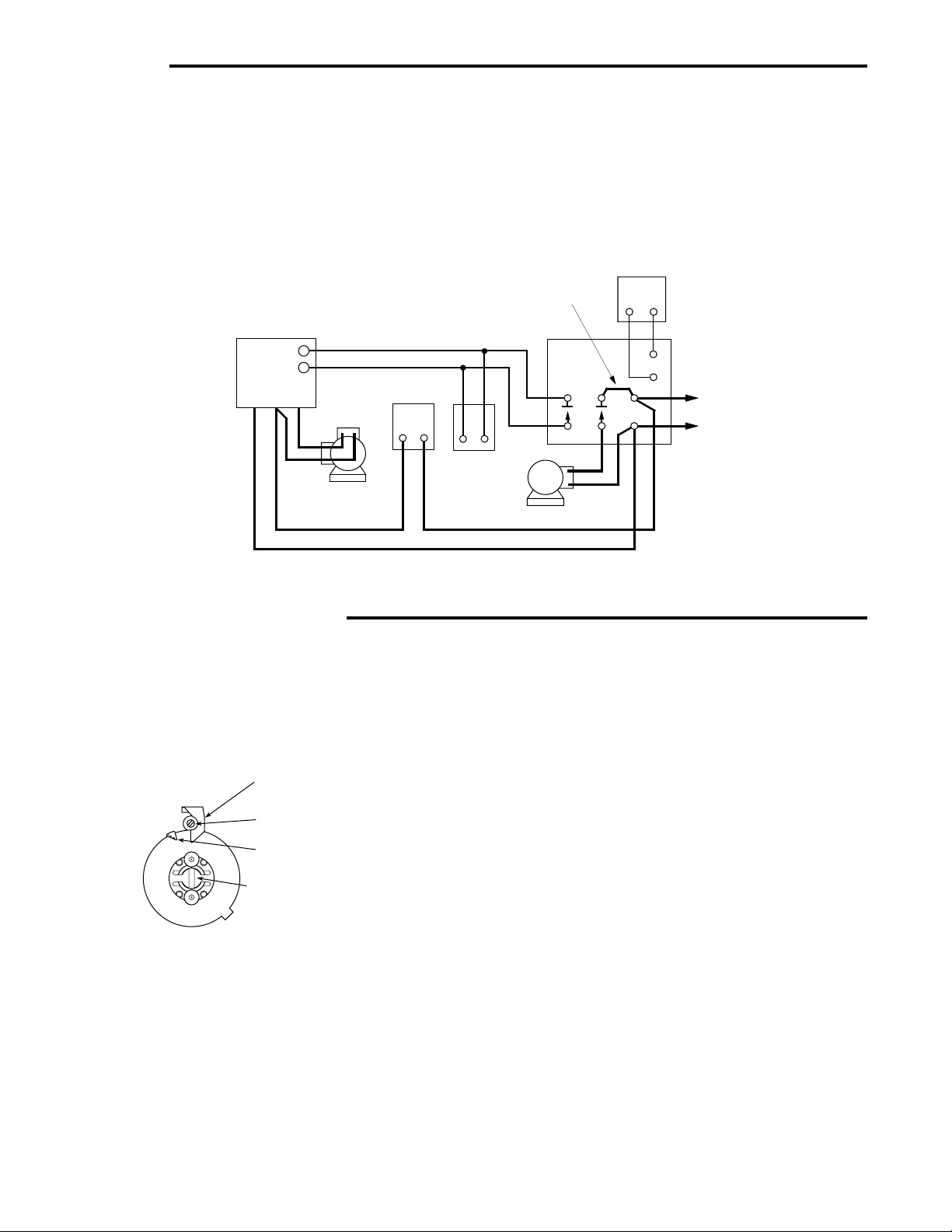
LOW LIMIT APPLICATION — This diagram shows a common
circuit on an oil fired heating system that also heats domestic hot
water which is stored in a tank.
TYPE 668 OIL
BURNER CONTROL
(LINE VOLTAGE)
T
T
HIGH LIMIT
CONTROL
IGNITION
TRANS.
LOW LIMIT
CONTROL
BURNER
MOTOR
Low limit control maintains domestic hot water temperature all
year round.
When thermostat calls for heat, burner and circulator operate.
5
6
THERMOSTAT
T
T
1
3
2
4
HOT
LINE
N
FIELD
INSTALLED
JUMPERS
TYPE
829A RELAY
CIRCULATOR MOTOR
SETTING THE CONTROL
CONTROLS WITH ADJUSTABLE DIFFERENTIAL
The movable indicator points to the temperature at which the
contacts open. The fixed indicator points to the temperature at
which the contacts close. The difference between these two
indicators is the differential.
“B” FIXED INDICATOR
(CUT-IN POINT)
“C” DIFFERENTIAL
ADJUSTING SCREW
“D” MOVABLE INDICATOR
(CUT-OUT POINT)
“A” ADJUSTING
SLOT
To set the control:
1. Use a screwdriver in the adjusting slot (A) on the front of the
control to turn the dial so that the fixed indicator (B) points
to the temperature at which the contacts will close.
2. Turn the differential adjusting screw (C) until the movable
indicator (D) points to the temperature at which the contacts
will open.
2
Page 3

WHITE-RODGERS
Utilisateur: conservez ces instructions pour vous y référer au besoin!
SI VOUS NE LISEZ PAS ATTENTIVEMENT CES INSTRUCTIONS AVANT
D’INSTALLER ET D’UTILISER LA COMMANDE, VOUS RISQUEZ DE CAUSER
DES BLESSURES ET DES DOMMAGES MATÉRIELS.
Cette commande, conçue pour servir avec un système de
chauffage à eau chaude, est dotée d’un capteur qui est
immergé directement dans l’eau de la chaudière. Ceci lui
permet de détecter immédiatement les changements
rapides de la température de l’eau, évitant ainsi tout
décalage thermique.
La commutation est à ouverture sur hausse. La commande
peut être utilisée soit comme limiteur à minimum, soit
comme limiteur à maximum.
La commande est dotée de bornes spéciales qui
permettent de l’utiliser avec des circuits à basse tension
et à millivolts (avec générateur à thermocouple) ainsi
qu’avec les robinets à gaz et les charges motrices à la
tension du réseau.
TYPE 1145
RÉGULATEUR D’EAU CHAUDE
Immersion directe, différentiel réglable
INSTRUCTIONS D’INSTALLATION
DESCRIPTION
LA PRÉSENTE COMMANDE DOIT ÊTRE INSTALLÉE
PAR UN TECHNICIEN QUALIFIÉ.
Ne dépassez pas les charges nominales.
Tout le câblage doit être conforme aux codes et règlements
locaux et nationaux qui régissent les installations
électriques.
Cette commande est un instrument de précision qui doit
être manipulé avec soin. Elle peut se détraquer si elle est
manipulée de façon négligente ou si des composantes
sont déformées.
La commande a été calibrée avec précision lors de la
fabrication. Toute tentative de calibrer l’appareil annulera
la garantie de White-Rodgers.
Si un emplacement de la commande est recommandé par
le fabricant de la chaudière, alors veuillez vous y conformer.
Si aucun emplacement n’est suggéré, veuillez suivre les
conseils suivants.
Pour utiliser la commande comme limiteur à maximum, la
situer dans la section la plus chaude de la chaudière, qui
est habituellement la partie supérieure. Ne pas installer
un limiteur à maximum dans la partie de la chaudière où
se trouve l’échangeur de chaleur qui fournit l’eau chaude
domestique.
PRÉCAUTIONS
ATTENTION
Afin de prévenir les chocs électriques et les
dommages matériels pendant l’installation,
coupez l’alimentation électrique au panneau de
distribution principal.
AVERTISSEMENT
N’installez pas cet appareil sur des circuits qui
dépassent la tension nominale. Une tension trop
élevée peut endommager la commande et poser
des risques de chocs électriques et d’incendie.
INSTALLATION
Pour utiliser la commande comme limiteur à minimum, la
situer dans la partie de la chaudière qui chauffe l’eau
chaude domestique.
Lorsque la commande est serrée dans la chaudière, il est
important de forcer uniquement sur l’écrou hexagonal afin
de ne pas endommager la membrane ou le mécanisme
de commande.
WHITE-RODGERS DIVISION
EMERSON ELECTRIC CO.
9797 REAVIS RD., ST. LOUIS, MO. 63123
(314) 577-1300, TÉLÉCOPIEUR (314) 577-1517
9999 HWY. 48, MARKHAM, ONT. L3P 3J3
(905) 475-4653, TÉLÉCOPIEUR (905) 475-4625
Imprimé aux É.-U.A.
PIÈCE No 37-0577E
Remplace 37-0577-3 & 37-9157
9548
Page 4

CÂBLAGE
Tout le câblage doit être conforme aux codes et règlements locaux et nationaux
qui régissent les installations électriques.
Si le fabricant de la chaudière ou du brûleur recommande
un schéma de câblage, alors veuillez vous y référer.
Sinon, voici le schéma d’un circuit recommandé.
UTILISATION COMME LIMITEUR À MINIMUM : Le
schéma ci-dessous illustre un circuit commun pour un
système de chauffage à mazout qui chauffe aussi l’eau
chaude domestique emmagasinée dans un réservoir.
COMMANDE DE BRÛLEUR
À MAZOUT TYPE 668
(TENSION RÉSEAU)
T
T
LIMITEUR À
TRANSFO.
D’ALLUMAGE
MOTEUR DE
BRÛLEUR
MAXIMUM
Le limiteur à minimum assure à l’année longue que la
température de l’eau chaude domestique sera maintenue
au niveau désiré.
Lorsque le thermostat d’ambiance exécute un appel de
chaleur, le brûleur et le circulateur sont mis en marche.
5
6
THERMOSTAT
1
3
2
4
T
T
SOUS TENSION
RÉSEAU
N
LIMITEUR À
MINIMUM
MOTEUR DE CIRCULATEUR
CAVALIERS
INSTALLÉS
SUR PLACE
RELAIS
TYPE 829A
RÉGLAGE DE LA COMMANDE
COMMANDES À DIFFÉRENTIEL RÉGLABLE
L’indicateur mobile donne la température à laquelle les
contacts seront ouverts. L’indicateur fixe donne la température à laquelle les contacts seront fermés. La différence
entre les deux indicateurs représente le différentiel.
(B) INDICATEUR FIXE
(POINT D’ENCLENCHEMENT)
(C) VIS DE RÉGLAGE
DU DIFFÉRENTIEL
(D) INDICATEUR MOBILE
(POINT DE DÉCLENCHEMENT)
(A) FENTE DE RÉGLAGE
Pour régler la commande :
1. Introduire la pointe d’un tournevis dans la fente de
réglage (A) qui se trouve à l’avant de la commande.
Tourner le cadran pour que l’indicateur fixe (B) indique
la température à laquelle les contacts seront fermés.
2. Tourner la vis de réglage du différentiel (C) jusqu’à ce
que l’indicateur mobile (D) indique la température à
laquelle les contacts seront ouverts.
2
 Loading...