

Page 1
4400
WH!E
4
l
Model
reserved
rights
All
Machine
trademark.
Manual
registered
a
is
White
Inc.
instruction
Embroidery
Sewing
VSM
C2005
Home
White
wAii
Page 2

Page 3
I
5
ma
p.m
••
p.
p.
p......
..
a....a....I......
6
9
10
11
14
16
19
20
21
22
26
25
24
.....a..........i...........i..............15
27
28
30
30
31
...............•.•••••••••••
w
Contents
..........
.......
Installation
oftvvare
S
Driver
Driver
USB
USB
the
the
Using
Install
Message
Software
Port
Program
the
the
Corn
Run
Install
No
Embroider
to
Preparing
INSTRUCTIONS
SAFETY
Operation:
IMPORTANT
Machine
Connections
Power
and
Machine
Button
the
Switch
of
Power
Parts
Machine
Procedure
in
Bobbin
Bobbin
Threading
Start/Stop
Place
Wind
Pin
Threader
Spool
Vertical
Automatic
Top
Hoop
Hoop
Procedure
the
Hooping
Attach
Tension
the
the
Remove
Adjust
Page 4

.32
34
35
36
36
37
37
38
39
40
41
42
43
44
45
45
47
48
48
50
52
.52
53
54
54
Change
Design
A
Stitch
Bulb
Light
Accessories
C’Jiaizg’e
Change
Needle
tc.’
1rJ,efl
Change
Needle
Change
Cleaning
Howto
Panel
Selectors
.1ndicctors
Lubrication
Control
J’,’Iode
!i.’lode
Keys
Home
and
Software
Indicators
Navigator
Directional
Message
Cards
!.4emor,i
Memory
Using
Internal
Tools
Designs
vvith
V1orkirig
1:
Section
Stitch
To
Move
Options
Softvvare
Modules
Software
Module
.€11,j.licition
Design
Design
Open
Navigator
Formats
2
Page 5

3
.55
56
.56
57
57
58
58
62
63
64
65
67
a
a..
a
.•••
aaaaa.•a
a..
a
a
as
a.
a
a
a
as......
a...
....
........
68
68
7L1
71
71
74
74
75
75
76
76
77
77
.
Design
Design
Horizontal
Flip
Rotate
Fhp
Tool
te
Design
.2?ota
Resize
Free
Fit
Designs
E.esigns
Merge
Iviaking
Colors
Designs
with
Working
Combining
Designs
Saving
Opening
.......
........
lettering
2:
Section
Designs
oftAIare
Lettering
S
Printing
Text
Letteritig
Create
.ace
Style
Size
Font
Change
Change
Handle
Handle
Handle
Width
Manipulation
Character
Height
Handles
Character
Character
Envelope
Handle
Area
Rotate
Alter
Settings
Density
Page 6
.78
78
79
80
80
81
83
83
85
86
94
96
97
98
99
100
105
..................
.._
a
a.
.
.
.
=
.
.
................................=..........93
.........
.
.
..
Messages
Designs
Tools,
...........•
Design
a
Control
Width
Compensation
Pull
Column
to
Lettering
Stitching
Underlay
of
Lettering
Lines
Two
Add
Digitize
uto
3:
Tips
ii
o
Secti
Success
Lettering
ArcedLettering
re
oftA,a
S
LargeLetters
Menus,
4:
Wizard
Section
File
Software
AutoDigitize
Edit
Tools
View
Explanations
Designs
Message
Bar
ncludecl
Error
Tool
I
4
Page 7
j
Installation
Software
speeds
installing
but
White
Computer
vary,
your
minutes
takes
system.
few
a
any
on
only
software
-
-
‘
Installation
Software
Page 8
install
Driver
USB
to
need
will
the
users
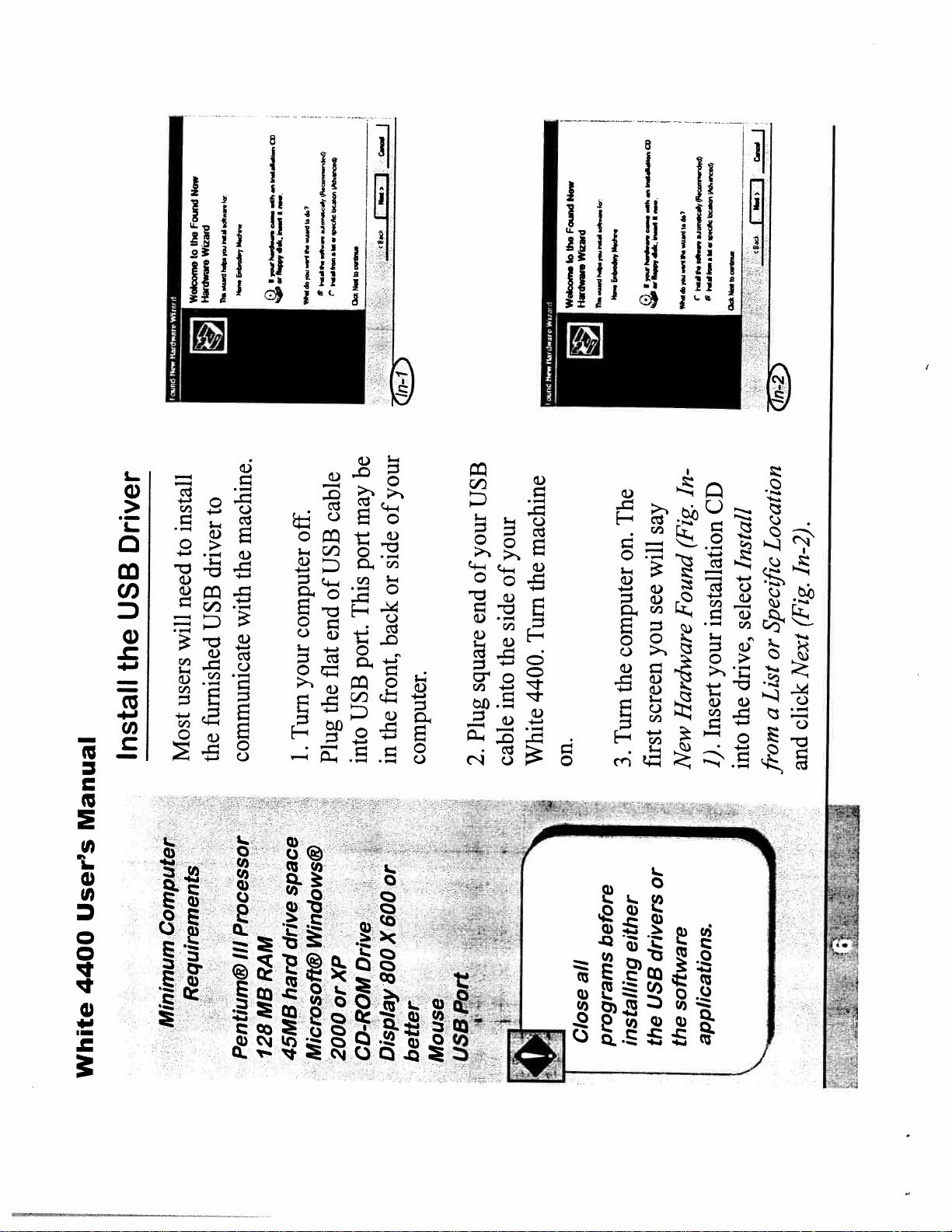
Install
Most
Now
Found
the
Wizaid
to
Hardww
Wolcocno
IIr
to
machine.
driver
the
with
USB
furnished
the
communicate
e
C)
%
off.
computer
your
Turn
1.
.4...r
.*...
rmd..
r
r
cable
USB
of
end
flat
the
Plug
—
iJ
j
ad
be
your
of
may
side
port
or
This
back
port.
front,
USB
the
into
in
USB
your
of
end
square
Plug
computer.
2.
machine
your
of
the
side
Turn
the
4400.
into
cable
White
New
Found
the
l
Hwd
Welcome
on.
E
-
fl4.b*4.r
The
on.
computer
the
Turn
3.
.
I
.u..dl.4.1
ie”w—
*.Ile.
C;)
say
will
see
Found
you
Hardware
screen
first
New
.*....
e..
rdF.
N
e
V
In-
CD
(Fig.
Install
installation
select
your
drive,
the
Insert
1).
into
a—’
1
1
r
Location
In-2).
(Fig.
Specflc
or
Next
List
a
click
and
from
Manual
User’s
4400
White
Computer
Processor
Ill
Requirements
Minimum
Pentium@
space
drive
RAM
hard
MB
128
45MB
or
600
Windows@
X
Drive
800
orXP
Microsoft@
CD-ROM
2000
Display
Mouse
better
Port
USB
before
all
Close
programs
or
either
drivers
USB
software
the
installing
the
applications.
Page 9
-4
I-
Installation
Software
-
Wizard
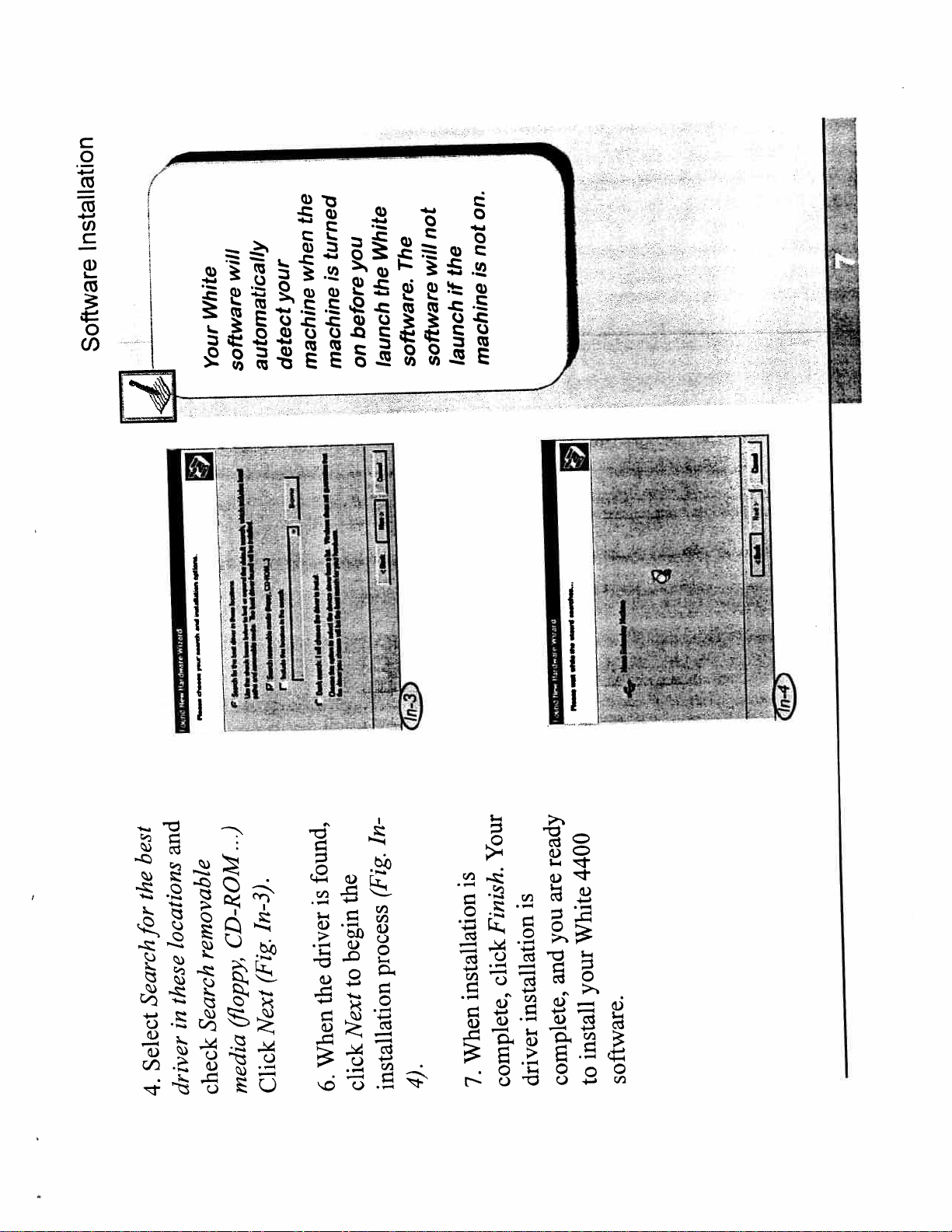
will
White
Your
software
the
turned
you
is
when
your
before
on
machine
machine
detect
automatically
White
The
the
software.
launch
on.
not
not
will
the
is
if
machine
launch
software
twdc.,c
Mc.,
ro.Jn
and
best
the
for
locations
these
Search
in
Select
driver
4.
In-3).
CD-ROM...)
removable
(Fig.
(floppy,
Search
check
Next
Click
media
found,
the
is
begin
driver
to
the
Next
When
click
6.
In(Fig.
process
4)
installation
Your
ready
is
are
is
Finish.
you
click
installation
installation
When
driver
complete,
7.
4400
White
and
your
install
software.
to
complete,
Page 10
J
.*
t.
I’w
n1
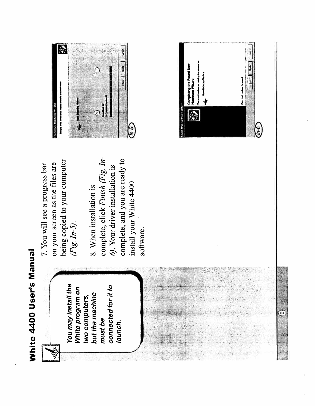
are
bar
progress
a
see
will
You
7.
Manual
User’s
4400
files
computer
the
your
as
to
screen
copied
your
being
on
the
install
may
In-5).
(Fig.
on
program
computers,
In
(Fig.
to
is
ready
is
are
Finish
installation
you
click
installation
When
8.
complete,
machine
be
the
and
driver
Your
6).
complete,
to
it
for
4400
White
your
install
software.
‘?H
White
You
[4
White
two
but
launch.
connected
must
\
Page 11
Installation
Software
1k-
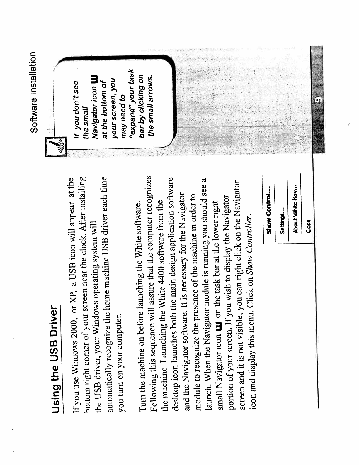
the
at
appear
will
icon
Driver
USB
the
Using
w
see
icon
don’t
small
you
If
USB
a
XP,
or
2000,
Windows
use
you
If
Navigator
the
installing
After
will
clock.
system
the
near
operating
screen
your
Windows
of
your
corner
driver,
right
USB
the
bottom
on
of
you
bottom
the
at
task
to
your
screen,
need
may
your
clicking
by
“expand”
bar
time
each
driver
USB
software.
White
the
machine
home
launching
the
before
computer.
on
recognize
your
on
turn
you
automatically
arrows.
small
the
the
recognizes
from
computer
software
the
that
4400
assure
White
will
the
sequence
Launching
this
machine
the
machine.
the
Following
Turn
a
see
to
software
order
should
Navigator
in
the
application
for
you
machine
design
the
of
necessary
main
is
It
the
presence
both
the
software.
launches
recognize
icon
to
Navigator
the
module
and
desktop
right
Navigator
lower
the
the
at
running
is
bar
display
to
task
wish
module
the
you
on
If
W
Navigator
icon
screen.
the
your
When
of
Navigator
small
launch.
portion
Navigator
the
ConoL.
ow
on
Controller.
click
Show
right
on
can
Click
you
menu.
visible,
this
not
is
it
display
and
and
icon
screen
Nov...
Whte
About
Settings...
close
Page 12
this
port...”
COM
“No
saying,
screen
your
on
Message
Port
message
a
get
Corn
you
No
If
Follow
correctly.
installed
not
is
driver
USB
the
correct.
to
means
steps
usually
these
on.
is
it
while
computer
the
from
off.
cable
USB
the
computer
the
Unplug
1.
Turn
2.
computer.
the
into
back
cable
computer.
USB
the
Plug
3.
the
on
Turn
4.
found,”
hardware
“New
stating,
message
Windows
Microsoft
A
5.
appears.
Driver
USB
drive.
the
Install
CD-ROM
the
into
chapter
this
in
CD
4400
instructions
White
the
the
Insert
6.
Follow
7.
driver.
USB
the
reinstall
to
Manual
User’s
4400
White
is
driver
need
USB
you
The
that
the
the
with
on
CD
located
same
application
software.
..—
—
.4-..
-
Page 13
Installation
Software
may
different
Different
have
computers
I
I
to
to
Go
menu
drive.
assigned
Start
CD
the
the
letters
of
My
drive.
on
click
letter
CD
drive
your
the
Computertosee
and
I
j
iJlI1[L.
01
you.
t
Øoo.Nne,t
wi
fu,
mds
Wid
ofoprogai.
na*
the
tntunetreSoxC.
type
-
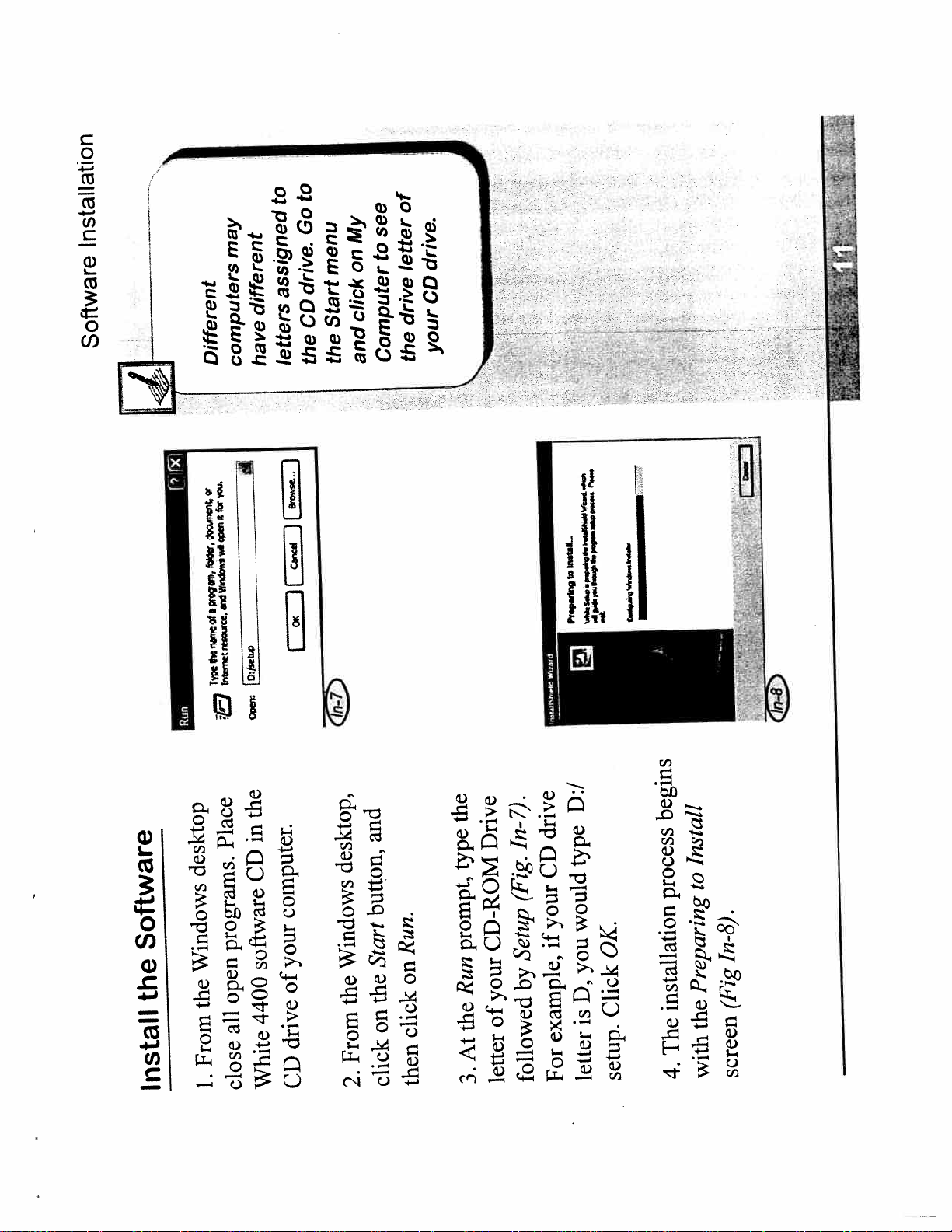
Place
desktop
Software
the
Install
programs.
Windows
open
the
all
From
1.
close
jierot..1
ir
ra.
10:et
ei
the
in
CD
computer.
your
software
of
4400
drive
CD
White
and
desktop,
button,
Run.
Start
Windows
on
the
the
on
click
From
then
click
2.
the
Drive
In-7).
type
prompt,
CD-ROM
Run
your
of
the
At
letter
3.
Ps....
ki.L.
Pt.p.dnta
D:/
drive
type
CD
(Fig.
your
would
if
Setup
by
followed
you
D,
is
example,
letter
For
C—
OK.
Click
setup.
begins
Install
to
process
In-8).
Preparing
installation
The
4.
(Fig
the
screen
with
Page 14
W.ib
I..
W.d
*1
I.Iid4
..
La
I.
1I_
,a..
W.
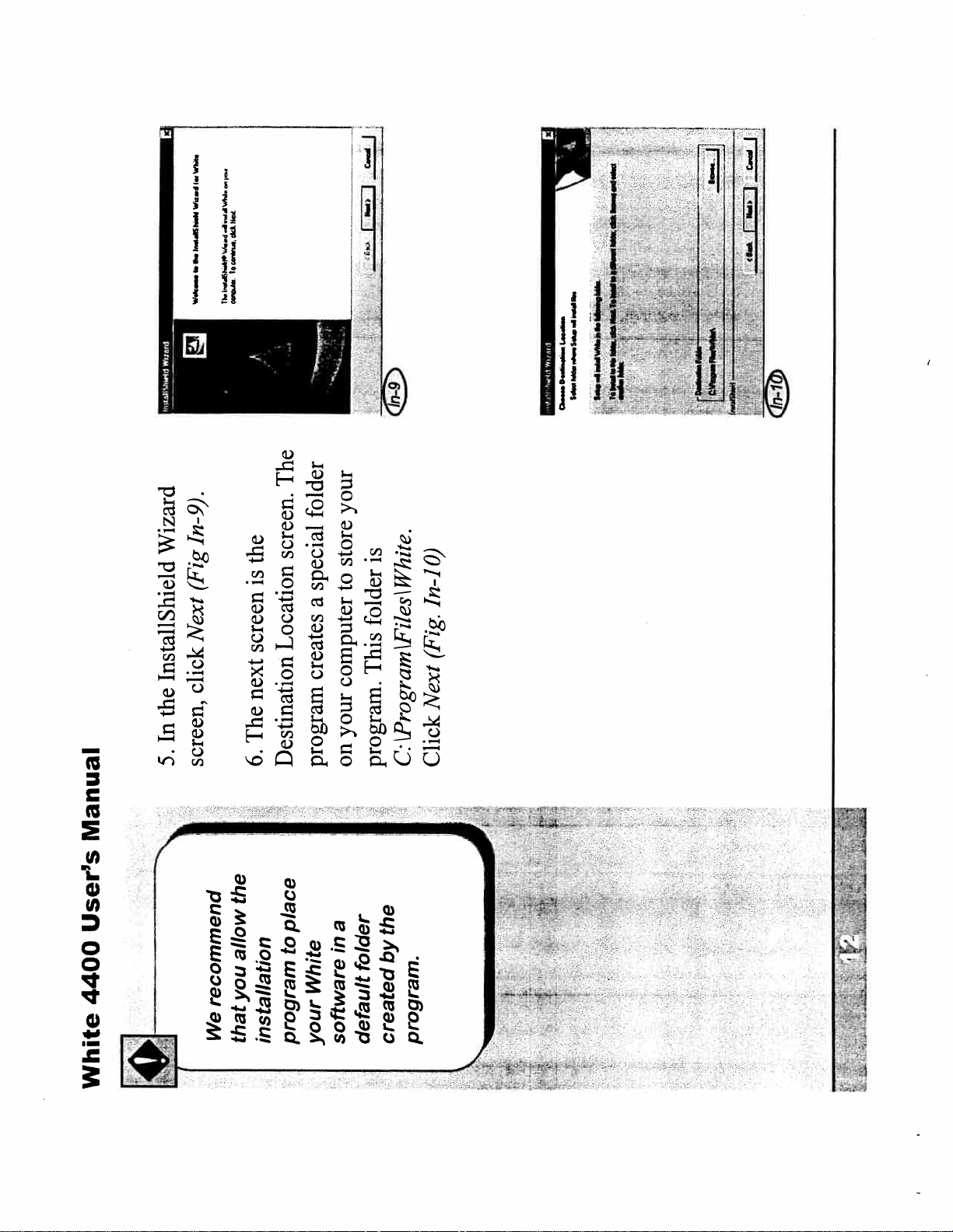
In-9).
Wizard
(Fig
Next
InstallShield
click
the
is
screen
next
the
In
5.
screen,
The
6.
C.d
Ii..*
j
.
The
your
folder
screen.
special
is
store
to
a
folder
Location
creates
This
computer
your
Destination
on
program
program.
0)
White.
\
In-i
Files
(Fig.
gram
Next
Pro
C.
Click
a..—
Manual
User’s
4400
White
IIhI
the
place
allow
you
recommend
We
that
to
installation
program
a
in
White
software
your
the
by
folder
created
default
4-
program.
\-
Page 15
Installation
Software
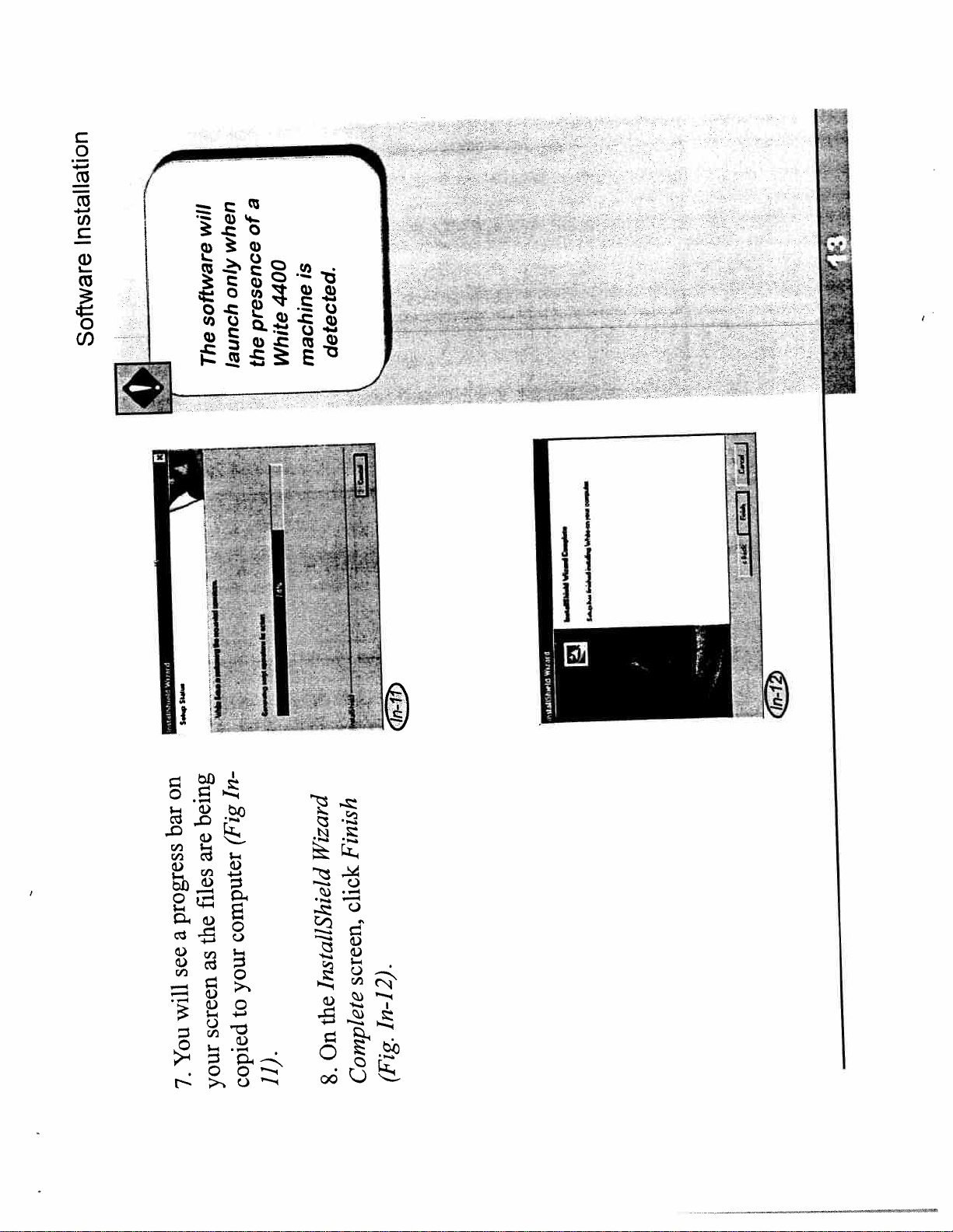
will
when
only
software
The
launch
i)
\
a
of
is
4400
presence
White
the
machine
-
j
detected.
$i.—..
S.b
on
bar
progress
a
see
will
You
7.
In
being
(Fig
are
files
computer
the
as
screen
your
your
to
1]).
copied
Finish
Wizard
click
screen,
InstallShield
the
On
8.
In-12).
(Fig.
Complete
Page 16
t
‘W
4%’4
Th
tprwri.
rm
ra
vqcz
‘4
wVfln.;
mt
O
[z’
n-I
Program
the
Run
Manual
User’s
4400
White
should
the
USB
the
computer
program,
with
the
and
on,
run
be
To
1.
both
machine
more
computer
have
Your
may
both.
to
attached
cable
port,
USB
should
connect
one
you
than
but
always
on
If
icon
In-13).
White
(Fig.
the
on
desktop
Click
2.
your
to
one,
assigned
machine
your
is
same
the
which
a
In-
detect
(Fig.
error
not
an
does
appear
will
machine,
software
White
drive,
home
your
to
machine
message
the
14).
at
your
of
appear
detected,
is
will
side
W
right
machine
icon
the
If
3.
bottom
small
a
the
of
module
indicating
running.
is
screen,
Navigator
the
software
computer
that
the
the
of
appears
screen
software
opening
4400
In-15).
The
(Fig.
White
4.
;:.::
-
•
“.-
-
•--:-
...
-
Page 17
Operation
Machine
i1
to
read
new
this
are
you
If
through
embroidery,
you
assure
before
to
begin
section
-
success.
your
to
Operation:
Embroider
Preparing
Machine
Page 18
If
in.
machine.
plugged
precautions
shock:
when
safety
basic
INSTRUCTIONS
embroidery
following:
the
this
electric
of
using
including
risk
unattended
left
be
appliance,
the
before
never
SAFETY
followed,
electrical
be
an
reduce
should
To
instructions
always
using
IMPORTANT
When
all
Read
should
Danger
An appliance
relamping.
immediately
electric
before
outlet
unplug
electric
the
Always
from
fire,
bulb.
burns,
watt
of
15
risk
of
the
type
cleaning.
appliance
this
same
before
reduce
with
and
unplug
To
bulb
using
after
Always
Replace
Warning
stable
suitable
on
placed
when
only
persons:
machine
to
injury
embroidery
or
shock
Operate
table.
this
in
necessary
is
attention
manufacturer
described
the
as
by
use
children.
Close
near
intended
toy.
or
a
by
as
used
used
is
be
recommended
its
for
only
attachments
to
only
appliance
appliance
allow
Use
not
Do
1.
this
this
Use
2.
when
manual.
plug.
or
damaged,
or
cord
nearest
the
to
dropped
damaged
a
been
has
it
has
if
appliance
it
if
the
or
appliance
return
manual.
this
properly,
this
water,
in
into
operate
working
not
contained
Never
3.
as
dropped
is
it
or
repair,
examination,
for
center
adjustment.
service
or
mechanical
dealer
or
authorized
electrical
Manual
User’s
4400
White
N
to
love
Children
The
embroidery
watch
machines.
a
not
is
machine
are
caution
children
Use
toy.
when
present.
_--1-
---
30W.
60Hz
parameter
120V
is
rating
Electrical
THESE
SAVE
INSTRUCTIONS
Page 19

Operation
Machine
other
or
place
not
Do
fingers
or
the
hold
under
to
needle
objects
is
fabric
machine
while
straighten
running.
It
THESE
INSTRUCTIONS
SAVE
thread.
machine
and
openings
air
the
of
cloth
embroidery
loose
the
any
with
and
of
dust
lint,
openings
of
appliance
the
ventilation
operate
accumulation
Keep
from
Never
free
blocked.
4.
used
being
are
opening.
products
any
into
(spray)
object
aerosol
any
insert
or
drop
Never
5.
where
outdoors.
operate
use
not
not
Do
Do
7.
6.
then
plug,
the
position,
grasp
(“0”)
off
the
unplug,
To
to
cord.
on
administered.
controls
all
being
turn
is
pulling
outlet.
by
from
oxygen
disconnect,
where
To
8.
or
unplug
plug
not
Do
9.
remove
is
care
Special
parts.
moving
all
from
away
fingers
cord.
Keep
the
10.
not
can
plate
wrong
needle.
The
plate.
machine
needle
embroidery
the
break.
proper
to
the
use
around
needle
the
Always
11.
required
cause
any
embroidering.
while
fabric
or
making
when
break.
to
it
hoop
the
machine
causing
needles.
push
needle
bent
use
not
Do
12.
or
pull
not
Do
13.
embroidery
the
the
deflect
Unplug
14.
may
or
other
outlet
needle
electrical
from
changing
as
such
machine
area,
needle
embroidery
the
in
unplug
bobbin.
Always
15.
threading
adjustments
manual.
any
making
instruction
the
when
in
or
mentioned
lubricating,
covers,
adjustments
removing
servicing
user
when
Page 20

continued
Reference
For
Precautions
Safety
Manual
User’s
4400
Instructions
These
Save
the
you
sure
have
could
under
that
Inc.
Sewing
VSM
per
needle,
a
zip
a
12
44145-80
Parkway
OH
Viking
31000
Westlake,
—
-
I_-V
-
I
White
Make
don’t
anything
fabric
break
like
:
Page 21

Operation
Machine
the
parts
the
with
machine.
of
your
Familiarize
yourself
of
names
you
its
help
will
This
Winder
Bobbin
felt
learning
operation.
in
and
Power
switch
Main
connectors
connection
USB
keys
lamp
I
Machine
the
of
Parts
Dial
Thread
Tension
Upper
Winding
Bobbin
Selection
Display
holder
Embroidery
hoop
Page 22

Connections
Power
and
switch
Switch
Power
Manual
User’s
4400
White
to
switch
position
Turn
OFF
power
unplugging
from
before
source.
cord
...
1-
-
•
Slot
2-off
Start/Stop
-
A
Card
1-on
B-
Connection
USB
-
C
I
-‘•
-
-
L
Page 23

—
_4.’
Operation
Machine
work
your
before
at
Look
space
start
the
has
assure
hoop
to
the
that
button
pressing
to
space
freely.
move
sufficient
STM
..J__
to
Button
StartiStop
once
button
machine.
this
the
start
Press
the
stop
to
again
it
Press
machine.
Note:
that
sure
be
other
start
the
to
objects
no
check
pressing
Before
are
there
button,
the
be
to
under
fabric
the
needle.
embroidered
than
Page 24

STOP
Bobbin
Wind
Manual
User’s
4400
on.
in
it
pin,
turn
and
spool
machine
horizontal
the
in
the
On
Plug
1.
2.
wind
-
can
to
spool
closest
pad,
cap
felt
the
spool
place
and
order,
thread,
of
this
your
bobbin
on
spool.
thread
of
size
the
your
match
of
to
color
the
small
shown.
as
the
inside
guides
from
through
through
bobbin
thread
the
the
thread
on
Pass
Place
3.
more
a
for
4.
hole
the
on
and
the
shaft
on
the
on
groove
the
spring
the
Match
to
bobbin.
bobbin
the
of
side
Press
right.
the
shaft.
to
the
shaft
onto
winder
bobbin
the
bobbin
the
push
begin
wound
to
has
button
Start/Stop
the
bobbin
the
press
Start/Stop
After
the
times,
Press
5.
several
winding.
winder
bobbin
tail
thread
the
bobbin.
trim
the
and
of
top
again
the
from
button
when
disengage
not
the
directional
speed
or
down
and
slow
to
up
the
.e
Use
6.
full.
keys
is
when
stop
bobbin
full.
is
winding.
.L;c
t’
White
You
Ic!
thread
colored
bobbin
the
fabric
invisible
fabric.
reverse
appearance
The
does
the
automatically
Press
bobbin
Page 25

so
-
Operation
—____
Machine
the
winding
spare
Keep
the
when
have
finish
will
wound
you
that
bobbins
plentyto
the
remove.
to
pushing
up
by
thread
wind.
to
without
embroidery
large
bobbin
Use
stopping
designs
your
winding
bobbin.
for
automatically
complete
to
stop
not
again
winder
the
will
button
Winding
Start/Stop
full.
the
NOTE:
is
Press
bobbin
bobbin.
7
straight
bobbin
from
the
shaft
Pull
left.
bobbin
the
the
to
shaft
Disengage
bobbin
8.
rn
Page 26

I
A
in
Bobbin
Place
Machine
to
bobbin
lever
the
to
small
the
cover
open
moving
by
Slide
area
A.
B
right.
the
the
the
in
into
thread
the
bobbin
the
with
Insert
shuttle,
B.
indicator
the
cover.
by
bobbin
shown
the
direction
under
the
toward
around
channel
the
thread
the
through
Guide
finger
C.
toward
thread
the
it.
Pull
cut
to
back.
the
you
D
by
and
right
the
cover
place
on
in
side
bobbin
the
left
the
lightly
down
Replace
D.
placing
place.
into
snap
to
pressing
Manual
the
User’s
4400
___
White
bobbin
check
the
periodically
of
Visually
thread
level
remove
completed
you
as
your
runs
doesn’t
the
bobbin
and
your
If
embroidery.
out
to
can
navigate
you
easily
stop,
machine
begin
to
where
need
point
the
you
Navigator
the
software.
using
Page 27

Operation
Machine
L
1
i
the
flows
through
thread
The
freely
is
the
foot
when
presser
path
when
is
It
restricted
raised.
is
foot
Always
presser
the
lowered.
presser
threading.
the
for
foot
raise
thread
to
foot
presser
Threading
Raise
Procedure
Top
1.
its
in
is
needle
the
position
that
most
machine
Assure
upper
2.
the
by
spool
from
indicated
path
thread
Run
3.
through
and
machine.
on
arrows
numbered
guides
foot,
behind
presser
thread
Pass
Lower
5.
4.
shown.
as
needle
thread
Page 28

Threader
Automatic
Manual
the
behind
above
thread
just
the
guide
placing
final
the
After
through
automatic
the
thread
can
using
device.
you
needle
the
needle,
raised,
upper
foot
through
presser
the
thread
With
1.
threading
bring
the
on
foot.
described
presser
as
page.
the
path
Lower
2.
preceding
thread
A
stops.
threader
through
it
the
until
passed
move
and
Lower
is
hook
forward
small
lever
the
across
needle.
thread
the
of
the
eye
Pull
3.
the
hook
right.
threader
to
The
the
left
from
back.
move
and
up
Gently
lever
4.
threader
the
through
thread
of
thread
the
pull
eye.
will
needle.
the
of
ioop
eye
the
the
Grasp
5.
behind
User’s
4400
White
not
does
automatic
the
If
Vi
needle,
assure
the
to
thread
threader
check
the
the
of
that
eye
aligned
is
it
that
and
the
with
inserted
is
needle
needle
go
will
it
as
high
as
slot.
the
in
you
the
that
care
Take
button
press
not
Start/Stop
do
threading
procedure.
during
‘-
\
‘4
Page 29

Operation
-
Machine
lul-
colors
can
you
decorative
a
For
two
thread
effect,
through
thread
of
80/
an
needle
the
as
large
a
Use
needle.
same
that
so
90/14,
such
or
12
size,
both
will
eye
the
threads.
accommodate
included
Pin
Spool
is
pin
spool
vertical
Vertical
A
it
make
to
machine
your
with
sometimes
certain
with
work
to
easier
vertical
is
It
your
use
spools.
to
of
helpful
types
use
to
time,
wish
you
when
pin
spool
a
wind
same
the
you
at
when
as
threads
such
two
the
on
placed
is
hole
pin
round
spool
small
vertical
the
The
bobbin.
into
cap
not
is
It
machine.
the
of
top
spool
spool
a
vertical
use
the
to
using
when
necessary
I
pin.
Page 30

Procedure
Hooping
Manual
to
Place
behind
marker
desired
the
fabric
stabilizer
embroidery.
of
the
for
center
removable
suitable
of
the
Use
1.
mark
piece
placement
a
H-i).
(Fig.
fabric
the
of
the
back
templates
on
the
the
of
one
the
out
it
from
cut
H-2
and
Fig.
in
manual
Remove
shown
2.
this
your
of
somewhat
ring
fit
inner
should
the
It
hoop.
inside
border.
snugly
outer
embroidery
over
as
the
fabric
crosshair
your
Adjust
on
center
the
H-2.
mark
Fig.
in
center
Position
3.
the
shown
ring
of
hoop
thickness
outer
the
the
embroider.
on
will
you
accommodate
thumbscrew
to
fabric
User’s
4400
White
two
are
There
Li
of
-
types
embroidery
main
stabilizer
Choose
and
cutaway
stabilizer
way.
teara
cutaway
and
fabrics
unstable
knit
for
other
it
better
because
fabrics
support.
provides
for
way
woven
teara
Use
stable
4.
fabrics.
\
Page 31

Operation
--
Machine
Li
run
the
hoaping,
across
forefinger
After
lightly
your
It
-
ripples
not
surface.
fabric
should
produce
surface
the
fabric
r
the
he
of
rat
remain
taut
to
be
enough
should
flat.
the
template
inside
the
ring
inner
keeping
the
ring,
Place
outer
4.
mark
You
center
H-3).
the
(Fig.
over
fabric
the
position
on
in
-
the
ring
force
outer
to
the
need
into
not
ring
should
inner
while
fabric
the
pressure
gentle
smoothing
use
gently
rather
been
has
ring
inner
the
When
surface.
5.
the
that
with
the
sure
of
be
to
aligned
still
crosshair
check
center
the
inserted,
(Fig.
fabric
the
on
is
mark
center
template
H-4).
a
the
in
it
from
put
use.
and
template
the
future
H-5)
for
(Fig.
place
Remove
fabric
6.
C
safe
Page 32

‘I,
Hoop
the
Attach
Manual
User’s
4400
hoop
outer
round
the
two
on
the
Locate
1.
extensions
if
during
remove
may
hoop
the
the
on
Locate
slots
carriage.
H-6).
hoop
(Fig.
ring
corresponding
machine
Use
any
or
change
to
bobbin
do
you
reason.
that
and
slots
the
round
with
the
Align
2.
extensions
is
hoop
the
loosen
the
in
hoop
the
to
H-6).
(Fig.
downward
hoop
press
the
gently
attach
arrow
tab
Hoop
the
large
silver
the
the
by
Locate
Remove
1.
indicated
H-7.
Fig.
in
to
up
tab
the
hoop
in
the
lightly
lifting
Press
2.
while
release.
White
You
the
embroidery
needed
the
other
care
not
fabric
when
removed.
\
Page 33

Operation
Machine
for
tension
Examine
embroidery
proper
looking
column
by
satin
a
at
balance
Range
fancy
reverse
The
the
from
side.
your
with
initials
included
script
satin
Stitch
are
and
out
one
stitches.
machine
the
from
it
the
for
back
examine
this
on
shown
characteristics
page.
Thread
Top
—
top
the
for
Tension
the
Adjust
Norma’
at
section
located
normal
dial
The
darker
a
with
adjustment
tension
machine.
numbered
the
the
is
of
marked
is
top
The
1.
the
tension
bobbin
normal
third
The
numbers.
the
behind
range
top
T-1).
one-third
one
is
between
balance
centered
thread
tension
(Fig.
side
each
to
thread
top
top
the
much
too
is
tightening
by
there
T-2,
Adjust
Fig.
In
thread.
2.
Loosen
higher
a
to
dial
the
Rotate
number.
thread.
top
top
the
little
too
is
loosening
by
there
T-3,
Adjust
Fig.
In
thread.
3.
lower
a
to
dial
the
Rotate
number.
thread.
a
an
produce
contact
to
center.
fail
balance,
service
remedies
tension
these
authorized
proper
If
Page 34

-
L
-
-
-;
J____
+
-
1
r
—
•
S
__.J
the
program,
Design
A
Stitch
the
run
To
1.
i44
L
on
be
attached
both
cable
should
USB
the
machine
with
:
on
icon
White
the
on
desktop.
Click
2
your
the
of
on
appears
screen
screen
software
Navigator
opening
4400
the
The
3.
White
with
to
the
go
On
screen,
St-i).
(Fig.
software
it
of
White
top
C:/
select
21807_Teddy.
and
Files/White/4400/
Open
design
gram
File,
Pro
Open
Designs/lesson_designs
top
the
to
from
Send
icon
the
on
Click
4.
Machine
St-2).
square
(Fig.
the
Navigator
on
the
In
Design
No
click
bar.
screen,
tool
labeled
Manual
User’s
4400
White
the
will
when
hoop
The
move
andthe
is
software
is
launched
machine
-
+
LJL
recognized
Page 35

it
of
Operation
Machine
.;
fabric
your
Hoop
.
—
that
of
so
piece
a
stabilizer
with
iI
hoop.
be
the
in
taut
should
It
is
free
and
wrinkles.
smooth
d
-
*wc’.r
I
‘
-
ThLIi
U
I
9
_M
St-3).
the
on
(Fig.
OK
click
Dfferent
click
Select
screen,
and
the
In
5.
Teddy
Design
main
(Fig.
the
to
Navigator
returned
the
of
are
You
screen
6.
St-4).
is
lowered.
attached,
is
is
machine
the
that
foot
hoop
the
presser
the
Check
7
threaded,
the
on
key
Start/Stop
the
Press
and
the
at
stop
will
machine
The
machine.
8.
the
the
Raise
change
color.
and
first
the
of
end
presser
the
Lower
foot
color.
thread
presser
color
is
Start/Stop
embroidering.
the
press
continue
and
to
foot
key
design
following
the
until
at
Repeat
complete.
changes
Page 36

Pin
4400
White
accessories
your
machine.
standard
with
are
1
r
1
:1
-
‘
Spool
Vertical
Tool
Screwdriver
Nippers
Thread
Ripper
.
.
Bobbins
L.
Oiler
Cap
Spool
Small
Accessories
Manual
User’s
4400
White
These
included
machine
Your
embroidery
oil
clear
machine
with
comes
sewing
your
be
keep
to
should
that
used
the
Oil
to
lubricated.
machine
according
Needles
this
in
diagram
chapter:
found
oiling
Thread
Page 37

Operation
Machine
is
your
sure
Be
machine
of
from
use
disengaged
type
and
same
only
power
bulb.
replacement
*
and
Change
power
Bulb
Light
off
Turn
1.
ii
the
on
electrical
from
unplug
screw
the
Loosen
2.
outlet.
the
of
side
left
the
at
cover
the
remove
and
cover.
machine
the
by
bulb
the
Remove
3.
of
out.
it
pulling
bulb
and
new
a
type
Insert
same
4.
hi
specification.
Page 38

Change
Change
to
Needle
When
appears
appears
needle
quality
the
if
or
stitching
rough
feels
whenever
changed
be
way.
any
needle
in
the
if
damaged
should
needle
The
or
substandard,
bent
be
be
to
to
needle
the
life-spans.
expected
detailed
other
particularly
is
and
needle
the
of
continuous embroidery
different
of
condition
hours
The
needles have
several
of
after
types
changed.
be
Generally,
Different
should
tests.
these
using
outlines
in
suitability
for
stitching
of
needles
quality
your
the
areas.
to
check
can
precision
important
or
You
to
the
the
of
from
edge
peendicular
needle
be
the flat
the
with
should
Remove
surface
-
flat
needle shaft
a
needle
on
The
it
bent
a
down.
place
for
and
shank
Checking
machine
needle
can
spots
burr
the
as
develop rough
used,
can
be
not
Needle
-
should
needle
needle
burred
burred
a
A
for
surface.
burrs.
flat
Checking
the
called
nail,
from
your
your
of
needle
across
the
surface
point
the
Remove
needle
the
thread.
scratches
of
or
sides
catches
all
embroidery
or
glide
point
the
and
fabric
the
discarded.
If
be
machine
should
damage
fingernail.
the
it
Manual
User’s
4400
White
q
N
i
that
bad,
is
suspect
you
needle
If
a
new
a
and
it
remove
discard
with
To
replace
needle.
an
with
in
safely,
needles
bottle
them
pill
old
place
safety
child
a
\%
Page 39

Operation
Machine
fresh
your
a
a
help
with
can
Replacing
one
needle
stitch
cleanly.
more
outlines
II
El
Change
Change
to
Needle
How
-!
the
to
power
the
off
Turn
1.
machine.
set
foot.
needle
presser
the
the
Loosen
Lower
3.
2.
Loosen
the
screwdriver
the
using
screw
any
with
with
or
screwdriver.
supplied
machine,
tool
suitable
the
remove
to
enough
needle.
only
side
as
flat
needle
The
go.
new
needle.
the
will
it
Insert
Remove
5.
4.
facing
be
will
needle
as
far
the
Tighten
you.
from
the
away
of
the
using
tool.
screw
set
screwdriver
needle
Page 40

Cleaning
Manual
and
electrical
power
off
from
Turn
1.
unplug
the
on
screws
the
Loosen
outlet.
2.
case
remove.
bobbin
and
the
plate
Remove
3.
needle
assembly.
a
sing
area
brush.
the
soft
Clean
small
4.
case
hook
the
the
bobbin
that
the
so
against
Replace
5.
rests
assembly
tab
stopper.
User’s
4400
White
bobbin
regular
a
the
on
Clean
area
on
when
more
and
frequently
basis,
embroidering
or
items
fleece
as
lint
high
such
.
terry.
Page 41

Operation
the
cover
oiling
Machine
each
down
of
Write
date
manual.
inside
this
the
of
on
and
electrical
power
off
from
Turn
Lubrication
1.
outlet.
unplug
the
the
of
on
side
screw
left
the
the
at
Loosen
cover
2.
the
remove
and
cover.
machine
at
oil
of
drop
machine
single
a
sewing
Place
clear
3.
-
the
on
frequency
indicated
point
drawing.
each
every
or
use.
of
month
each
hours
100
once
Recommended
Page 42

THREAD
SBAING
C)
C)
POSfl1ON
SELECT
o
o
CDLR
ERROR
INTERNAL
CARD
0
ci’
II
Panel
Control
Manual
User’s
4400
e
oft
panel
has:
control
machine
The
LED
lit,
Indicators
Indicators
Mode
Four
indicate
Selectors
Mode
Message
Four
Four
of
mode.
state
machine
Keys
Key
Directional
Four
Home
memory
in
perimeter
designs
design
Access
Trace
card
on
designs
Access
Select
center
to
hoop
moves
Home
k
When
_____________
lights
current
I
the
.:.‘:.:
White
Page 43

Operation
Machine
by
the
from
Select
directly
panel
designs
the
Memory
control
pressing
the
Use
key
internal
to
the
keys
design
press
the
then
and
select
Directional
key.
Select
the
embroidery
erase
Pressing
will
during
design.
current
The
outside
change
to
memory
pressed
operations.
be
internal
in
can
various
that
keys
user
access
to
designs
access
to
are
key
machine
this
the
Selectors
of
Press
Selectors
Mode
Mode
_____
Mode
The
the
100
number.
machine.
the
pattern
of
the
approximately
or
memory
select
to
the
keys
capacity,
within
2mb
a
stored
has
directional
are
the
Use
memory
designs
designs.
internal
These
to
the
trace
helpful
to
is
This
selection
stitched.
design
be
to
after
key
design
this
the
of
Press
design.
the
of
positioning
proper
determine
perimeter
side
the
at
external
an
slot
on
card
the
stored
into
designs
inserted
access
to
been
key
has
this
that
card
Press
memory
other
with
made
selections
confirm
to
key
this
Press
machine.
the
of
computer
a
on
key
“enter”
an
using
to
similar
is
It
keyboard.
keys.
Page 44

are
beside
lit
is
Following
lamp
LED
the
operations.
when
specific
mode
for
active
modes
the
has
of
Indicators
machine
is
mode
this
When
embroider.
to
display.
patterns
machine’s
select
your
may
on
You
titles
-
card.
by
through
memory
move
keys
backward
and
inserted
an
forward
on
or
Directional
move
right
keys
memory
and
in
left
the
designs
use
may
individual
you
time.
a
Directional
at
down
and
designs
may
the
by
You
The
indicated
center.
selection.
than
design
after
direction
other
the
in
point
hoop
displayed
is
light
This
-
the
starting
a
to
move
hoop
keys
the
from
working
are
you
whenever
lit
is
lamp
This
-
memory.
an
from
working
are
you
whenever
lit
is
card
lamp
memory
This
-
Mode
Manual
User’s
4400
White
descriptions
The
these
N
SELECT
—
Select
lit,
POSITION
INTERNAL
CARD
cD
D
‘D
the
Up
ten
Position
Directional
position
arrow.
internal
Internal
Card
inserted
—..
.
I-.-
Page 45

Operation
-
F
Machine
SEWING
D
the
when
display.
machine
machine’s
the
of
your
on
state
the
titles
of
these
THREAD
a
is
or
stitching
design,
a
while
key
stitching
is
Start/Stop
machine
the
the
using
that
ERROR
‘
t*L,:
thread
a
for
stopped
is
machine
the
that
code
error
change.
See
color
a
for
stopped
is
machine
the
attention.
taken.
needs
be
to
that
action
condition
and
a
beside
descriptions
lit
Indicators
are
is
lamp
LED
Following
Message
stopped
Indicates
-
Sewing
design.
temporarily
Indicates
-
break.
Thread
Indicates
-
Color
Indicates
-
Error
explanation
for
list
Page 46

in
and
to
down.
used
are
key
Home
the
Keys
surrounding
Home
keys
and
Directional
designs
through
navigate
to
keys
function
with
winder
the
cause
will
key
hoop.
the
“up
the
move
as to
well
as
bobbin winding,
slow
to
winder
the
cause
will
key
“down”
The
up,
Directional
Manual
User’s
4400
White
The
conjunction
functions,
speed
During
Page 47

Operation
Machine
also
designs
can
You
the
from
directly
select
by
the
panel
pressing
control
the
Use
Memory
keys
Internal
MGtmaton.
Dcsin
Rtrvffi
to
keys
b
wdcn
—
the
design
press
the
then
and
select
Directional
lJ
C
key.
Select
di
.1
MCaIDe.r.
(.w,
fl,f
‘.Wd
6kah
c
I
machine
is
your
Software
software
whenever
Navigator
launched
Navigator
The
and
software
machine.
computer
the
to
connected
is
the
This
with
on.
is
machine
communicates
the
internal
square
from
the
on
design
a
Memory
Internal
click
open
To
1.
design,
N-i).
any
(Fig.
loaded
Design
have
No
you
labeled
memory,
After
will
design
box.
the
current
the
below
of
name
shown
be
the
on
appears,
box
working
N-2)
Design
(Fig.
Retrieving
The
2.
“Currently
stating
Information
is
bar
Design
internal
your
progress
from
the
When
information
machine.”
pulling
nine
Different
first
the
Select
a
complete,
N-3).
(Fig
images
design
shows
memory
screen
Page 48

Ej
—
..-—
;._.
i,,---
—-
—
*
SSR7
#122
——•_________
IR*o.Me
ilimedHo
-____
ITHGaei
I26
oeoe
I
an
delete
to
individual designs.
the
to
it
send
to
icon
design
a
on
Click
4.
Manual
N-4).
(Fig.
stitching.
Navigator
of
begin
screen
may
main
You
N
the
on
shown
N-5).
are
(Fig
design
the
screen
of
the
of
colors
side
The
5.
right
Info
design
The
the
screen.
Thread
with
associated
the
the
in
of
shown
bottom
are
the
colors
near
The
6.
segments
box
the
send,
To
sending
System
by
System.
Design
to
changed
Design
be
may
colors
Send
the
the
to
on
design
click
other
are
screen.
and
the
of
bottom
system
design
associations
the
the
in
color
near
Changing
button
operations
N
with
Working
chapter
the
in
covered
Designs.
Design
Delete
delete
then
to
and
icon
Memory
Memory
design
Clear
Internal
a
in
on
Click
•
on
Click
•
designs
deleting
after
Memory
De-Fragment
design.
On
Click
individual
•
User’s
4400
White
the
grid
the
move
on
may
You
design
the
Hoop
In
pressing
Position
by
and
tool
mouse
the
moving
in
the
place
to
anywhere
the
design
hoop
allowed
De
deleted,
designs
the
several
After
l
I
E.
been
on
individual
click
have
the
Memory
area.
optimize
to
Fragment
storage
Page 49

Operation
Machine
L4i---
insert
to
card
sure
Be
the
the
the
on
to
Improper
card.
instructions
according
may
pins.
damaged
in
connector
result
insertion
-
-
..
..f
v•
-
p1I
c&!
card
PEC
the
Cards
Memory
Using
use
White-compatible
that
insert
cards
may
format.
memory
You
b?c.’?w*L*n..
Lrffl
b1necr*
[rj
N-7)
the
the
(Fig.
of
into
side
card
Design
the
the
at
on
slot
compatible
a
Click
card
Insert
1.
machine.
memory
1
—..
on
click
Designs.
Then
Card
bar.
color
Memory
the
to
next
box
Information
Design
labeled
tab
the
M!
—]
11
your
is
from
“Currently
bar
stating
progress
information
appears
pulling
box
on
Retrieving
N-8)
The
(Fig.
2.
working
screen
card design
Design
memory
Different
the
nine
Select
When
first
a
the
shows
complete,
machine.”
to
N
it
(Fig.
send
to
icon
Navigator
of
design
N-9).
images(Fig.
a
screen
on
main
Click
3.
the
..‘
I
embroidering.
begin
may
You
10).
Page 50

cii
oIfl
i®JVHJ
after
normal
scale.
to
scale
viewing
returns
scale.
Pan.
or
viewing
Out
the
Zoom
In,
increases
viewing
the
decreases
the
see
on
to
image
useful
In.
the
of
Zoom
particularly
is
during
movement
tool
areas
This
allows
any
in
size.
placed
be
hoop
to
the
by
design
the
allowed
allows
menu.
Options
the
Accesses
in
a
button
the Options
on
click
may
in
settings.
type
can
certain
You
-
change
to
Name
Tools
Manual
User’s
4400
White
[®J
Zoom
N
an
stitches
of
examine
To
area
[41
first
click
closely,
on
In
then
and
theZoom
on
icon
The
you
lets
tool.
tool
Pan
the
Pan
grid.
any
see
image
to
the
around
move
specific
4j
closely.
portion
location
Options
You
Machine
Navigator
Page 51

Operation
Machine
EnirWA.1
sei
Detection
complete
Use
to
Thread
F
Disable
the
closely
watching
machine
while
embroidering
only
tE
I
the
as
thread
breakage,
for
your
not
will
service
Consult
stop.
machine
fora
solution.
center
authorized
I
10.0
tL*
1,
?.
Vsicn
Oprirxn.
for
displayed
be
to
name
machine.
your
different
te.d0ám
)isaae*Co*
DiIik
Disable
-
break
check
a
thread
the
Placing
-
Control
Detection
Needle
Thread
Thread
I
a
your
if
displaying
helpful
be
disable
could
to
This
box
this
sensor..
in
thread
no
machine
and
The
when
signal
stopping
is
machine
occurred.
break
has
thread
break
thread
any
at
stop
NOT
WILL
break
to
box
this
on
checked.
Click
-
is
box
Color
this
when
Shadow
to
you
the
of
alloows
color
that
viewing
palette
the
color
a
change
see
to
problem
helpful
a
is
have
This
who
image.
individuals
preview
grey.
box
you
of
this
alerts
on
shades
that
Click
-
between
buzzer
the
Buzzer
disable
distinguishing
Disable
such
conditions
machine
breaks.
thread
certain
as
to
to
Page 52

I
jJJ
oa(a238
Id
-
tdi
3575d8238
r04”
I
3501’
sutdi
sutdi
from
ve
roi
hocç
The
c;)
I
I[
Stitch
To
Move
Manual
User’s
4400
in
or
point
forward
any
to
either
move
can
design,
You
the
or
forward
Move
beneath
time.
any
bar
slider
at
the
Using
backward,
one
by
backward
I.
a
on
segment
segment
color
clicking
full
by
color
you
resume
where
(FzgN-7),
display
or
begin
location
to
the
like
to
design
move
the
the
at
icon
would
end
bai
or
slider
the
beginning
of
the
like
arrow
the
would
reached
on
you
have
you
When
embroidering.
2.
click
where
embroider,
location
to
boxes
Stitch
count
Display
stitch
the
N-8).
Machine
between
_>,
and
(Fig.
will
location
hoop
the
message
proper
a
the
that
see
to
you
will
move
You
3.
warning
now
N-9).
your
at
(Fig.
location
embroidering
begin
designated
to
White
Page 53

Designs
with
Working
1:
will
get
chapter
you
This
help
designs
using
with
started
ways.
quickly
and
merge
many
Easily
in
original
make
to
own
resize
your
creations.
Section
Software
1:
Designs
Working
Section
with
Software
Page 54

Modules
Application
or
maj
two
of
Design
the
software
White
the
and
with
Design
work
the
you
In
such
lettering,
operations
and
designs.
designs.
designs.
add
or
lettering
from
designs.
to
designs
the
to
memory.
designs
Software
Manual
User’s
4400
White
Design
2I
Your
designs
create
can
edit
You
and
consists
modules:
the
on
running
while
machine.
designs
application
application,
Navigator.
designs
Open
Resize
as:
performing
•
•
Create
Rotate
•
•
Create
•
lettering
artwork.
Send
•
machine
Page 55

Designs
with
Working
1:
the
is
that
the
of
Navigator
software
part
in
machine.
the
with
communicates
the
are
in
functions
module
explained
this
The
Operation
chapter
Machine
Section
Software
Module
Navigator
C
—
—
‘—
module,
for
designs
Navigator
can:
the
In
you
Select
•
the
memory.
from
the
internal
from
stitching
designs
machine’s
the
memory.
from
internal
Delete
•
machine’s
I
7
I1
memory
application.
internal
designs
design
Send
machine’s
•
the
from
designs
the
Send
•
to
memory
designs
application.
internal
machine’s
select
and
design
the
View
•
to
in
inserted
point
cards
machine.
memory
the
into
from
specific
a
to
design.
Move
a
•
Page 56

Design
Open
Manual
User’s
4400
called
“languages”
use
Formats
Machines
4400
allows
White
Your
open
to
software
you
the
the
for
by
format
following
identified
be
machine
can
extension
The
letter
design
any
formats.
three
formatted
popular
embroidery
any
designs
for
home
you
White
your
for
although
number.
or
WTE,
format
is
name
native
design
The
machine
see
a
list,
For
machine.
section
Menu
the
complete
click
and
format.
this
menu
to
File
the
limited
to
not
Go
1.
are
this
of
end
the
chapter:
at
File
the
the
to
on
Go
click
icon.
or
l
Open,
Open
on
on
the
D-]).
click
(Fig
your
on
Double
opens
C:/White/4400/designs/
20208_duck
design
file
The
directory
Lesson_designs.
the
2.
it
selection
a
in
area
around
white
hoop
The
the
enclosed
D-2).
with
screen,
(Fig.
box,
represents
design
the
around
area.
embroidery
available
.
-
White
Page 57

Designs
with
Working
1:
Section
Software
design
area
the
white
The
around
DgiUzer
auto
the
stitching
Your
area.
maximum
represents
F
C
ttoHoop
center
Iext
T
fit
white
must
the
area.
inside
creations
V
H
erbca
Horizontal
lI.
IIIII:
I_
-
-
-
1
tt
1IITN
1
FiT
$
4
48
zzt
•
Ii
1
t
iiL
Design
Flip
Horizontal
Flip
menu,
select
fly-out
menu,
the
Tools
from
the
and
From
3.
Flip,
a
to
D-3).
(Fig.
Horizontal
select
changed
be
will
design
The
and
its
to
Undo
original
Edit,
the
of
image
mirror
returned
be
Click
D-4).
(Fig.
will
position.
duck
original
the
is
design
Flzp,
the
how
Tools,
see
click
to
Next,
Vertical
4.
Undo.
Edit,
Click
affected.
 Loading...