

Whirlpool WFM18, WFD18 Installation Instructions
80% SINGLE-STAGE MULTISPEED GAS FURNACE
INSTALLATION INSTRUCTIONS
Table of Contents
GAS FURNACE SAFETY................................................................2
INSTALLATION REQUIREMENTS................................................4
Tools and Parts ............................................................................4
Electrostatic Discharge (ESD)......................................................4
Location Requirements................................................................4
Installation Configurations ...........................................................7
Ductwork Requirements ..............................................................8
Electrical Requirements ...............................................................8
Gas Supply Requirements...........................................................9
Venting Requirements..................................................................9
INSTALLATION INSTRUCTIONS................................................10
Inspect Shipment.......................................................................10
Plan Vent System.......................................................................10
Install Ductwork..........................................................................14
Filter Specifications....................................................................15
Make Electrical Connections .....................................................16
115-Volt Line Connection of Accessories—
Electronic Air Cleaner.................................................................18
Make Gas Connections..............................................................18
Start-Up Procedure and Adjustment.........................................22
Complete Installation..................................................................26
Furnace Shutdown.....................................................................26
SEQUENCE OF OPERATION ......................................................27
Power Up....................................................................................27
Heating Mode—Mode DIP Switch Set to 1 STG Position.........27
Heating Mode—Mode DIP Switch Set to 2 STG Position.........27
Cooling Mode.............................................................................27
Fan Only Mode...........................................................................27
OPERATIONAL CHECKS.............................................................28
Burner Flame ..............................................................................28
Auxiliary Limit Control ................................................................28
Circulator Blower Speed ............................................................28
MAINTENANCE ............................................................................31
Annual Inspection.......................................................................31
Filters ..........................................................................................31
TROUBLESHOOTING ..................................................................32
Resetting from Lockout..............................................................34
ASSISTANCE OR SERVICE.........................................................36
Accessories ................................................................................36
ATTENTION INSTALLATION PERSONNEL
As a professional installer, you have an obligation to know the product better than the customer. This includes all
safety precautions and related items. Prior to actual installation, thoroughly familiarize yourself with this instruction
manual. Pay special attention to all safety warnings. Often during installation or repair, it is possible to place
yourself in a position which is more hazardous than when the unit is in operations.
Remember, it is your responsibility to install the product safely and to know it well enough to be able to instruct a
customer in its safe use. Safety is a matter of common sense...a matter of thinking before acting. Most dealers have
a list of specific good safety practices...follow them.
The precautions listed in this installation manual are intended as supplemental to existing practices. However, if
there is a direct conflict between existing practices and the content of this manual, the precautions listed here take
precedence.
Placeholder
Whirlpool® Model
WFM18, WFD18
WPIO-359B
Whirlpool® Home Cooling and Heating
14610 Breakers Drive
Jacksonville, Florida 32258
GAS FURNACE SAFETY
Recognize this symbol as a safety precaution.
Please adhere to the following warnings and cautions when installing, adjusting, altering, servicing or operating the furnace.
WARNING
Hazards or unsafe practices could result in property
damage, product damage, severe personal injury or death.
Goodman 1
CAUTION
Hazards or unsafe practices may result in property
damage, product damage, personal injury or death.
IMPORTANT SAFETY INSTRUCTIONS
Use only with type of gas approved for this furnace.
■
Refer to the furnace rating plate.
Install this furnace only in a location and position
■
as specified in the “Location Requirements” section
of these instructions.
Provide adequate combustion and ventilation air to
■
the furnace space as specified in the “Venting
Requirements” section of these instructions.
■
Combustion products must be discharged outdoors.
Connect this furnace to an approved vent system
only, as specified in the “Venting Requirements”
section of these instructions.
Never test for gas leaks with an open flame. Use a
■
commercially available soap solution made
specifically for the detection of leaks to check all
connections, as specified in the “Make Gas
Connections” section of these instructions.
Adequate clearance must be provided around the
■
vent-air intake terminals.
ANSI Box Install G 2009 in Goodman Folder
CAUTION
Hazards or unsafe practices may result in property
or product damage.
Always install furnace to operate within the furnace’s
■
intended temperature-rise range with a duct system
which has an external static pressure within the
allowable range, as specified in the “Complete
Installation” section of these instructions. See
furnace rating plate.
■
When a furnace is installed so that supply ducts
carry air circulated by the furnace to areas outside
the space containing the furnace, the return air
shall also be handled by duct(s) sealed to the
furnace casing and terminating outside the space
containing the furnace.
A gas-fired furnace for installation in a residential
■
garage must be installed as specified in the
“Location Requirements” section of these
instructions.
The furnace shall be installed so the electrical
■
components are protected from water.
■ Furnaces for indoor installation on combustible
flooring shall not be installed directly on carpeting,
tile or other combustible material other than wood
flooring.
Goodman 9
SAVE THESE INSTRUCTIONS
To the Installer
Before installing this unit, please read this manual thoroughly to familiarize yourself with specific items which must be adhered to,
including but not limited to: unit maximum external static pressure, gas pressures, Btu imput rating, proper electrical connections,
circulating air temperature rise, minimum or maximum CFM and motor speed connections and venting. These furnaces are designed
for Category I venting only.
2
WARNING
WARNING
If the information in these instructions is not followed
exactly, a fire or explosion may result causing property
damage, personal injury or loss of life.
— Do not store or use gasoline or other flammable vapors
and liquids in the vicinity of this or any other appliance.
— WHAT TO DO IF YOU SMELL GAS
• Do not try to light any appliance.
• Do not touch any electrical switch; do not use any phone
in your building.
• Immediately call your gas supplier from a neighbor’s
phone. Follow the gas supplier’s instructions.
• If you cannot reach your gas supplier, call the fire
department.
— Installation and service must be performed by a
qualified installer, service agency or the gas supplier.
Goodman 42
DANGER
CARBON MONOXIDE POISONING HAZARD
Special Warning for Installation of Furnace or Air Handling
Units in Enclosed Areas such as Garages, Utility Rooms or
Parking Areas.
Possible property damage, personal injury or death due
to fire, explosion, smoke, soot, condensation, electrical
shock or carbon monoxide may result from improper
installation, repair, operation or maintenance of this
product.
WARNING
To prevent property damage, personal injury or death due
to fire, do not install the furnace in a mobile home, trailer
or recreational vehicle.
WARNING
To prevent personal injury or death due to improper
installation, adjustment, alteration,
refer to this manual. For additional assistance or
information, consult a qualified installer, service agency
or the gas supplier.
Goodman 44
service
or
maintenance,
WARNING
This product contains or produces a chemical or
chemicals which may cause serious illness or death and
which are known to the State of California to cause
cancer, birth defects or other reproductive harm.
Goodman 45
WARNING
Carbon monoxide producing devices (such as an
automobile, space heater, gas water heater, etc.) should
not be operated in enclosed areas such as unventilated
garages, utility rooms or parking areas because of the
danger of carbon monoxide (CO) poisoning resulting from
the exhaust emissions. If a furnace or air handler is
installed in an enclosed area such as a garage, utility room
or parking area and a carbon monoxide producing device is
operated therein, there must be adequate, direct outside
ventilation.
This ventilation is necessary to avoid the danger of CO
poisoning which can occur if a carbon monoxide producing
device continues to operate in the enclosed area. Carbon
monoxide emissions can be (re)circulated throughout the
structure if the furnace or air handler is operating in any
mode.
CO can cause serious illness including permanent brain
damage or death.
Goodman 38
WARNING
Should overheating occur or the gas supply fail to shut
off, turn off the manual gas shutoff valve external to the
furnace before turning off the electrical supply.
Goodman 43
To prevent possible personal injury or death due to
asphyxiation, this furnace must be Category I vented.
Do not vent using Category III venting.
Provisions must be made for venting combustion
products outdoors through a proper venting system.
The length of flue pipe could be a limiting factor in
locating the furnace.
Goodman 66
WARNING
To prevent possible property damage, personal injury or
death due to electrical shock, the furnace must be located
to protect the electrical components from water.
Goodman 46
3
WARNING
Heating unit should not be utilized without reasonable,
routine inspection, maintenance and supervision. If the
building in which any such device is located will be
vacant, care should be taken that such device is
routinely inspected, maintained and monitored. In the
event that the building may be exposed to freezing
temperatures and will be vacant, all water-bearing pipes
should be drained, the building should be properly
winterized and the water source closed. In the event
that the building may be exposed to freezing
temperatures and will be vacant, any hydronic coil units
should be drained as well, and, in such case, alternative
heat sources should be utilized.
Goodman 47
INSTALLATION REQUIREMENTS
These instructions are intended as a general guide only for use by
qualified persons and do not supersede any national or local
codes in any way. Compliance with all local, state, or national
codes pertaining to this type of equipment should be determined
prior to installation.
Read this entire instruction manual, as well as the instructions
supplied in separate equipment, before starting the installation.
The installation of the furnace, wiring, warm air ducts, venting,
etc., must conform to the requirements of the National Fire
Protection Association; the National Fuel Gas Code, ANSI
Z223.1/NFPA No. 54 (latest edition) and the National Electrical
Code, ANSI/NFPA No. 70 (latest edition) in the United States, and
any state laws, local ordinances (including plumbing or
wastewater codes), or local gas utility requirements.
Local authorities having jurisdiction should be consulted before
installation is made. Such applicable regulations or requirements
take precedence over the general instructions in this manual.
This furnace design is certified by CSA International as a
Category I furnace in compliance with the latest edition of
American National Standard Z21.47/CSA Standard 2.3 for GasFired Central Furnaces, for operation with Natural gas or
propane. Consult the rating plate on the furnace for gas type
before installing.
Tools and Parts
Gather the required tools and parts before starting installation.
Read and follow the instructions provided with any tools listed
here.
Too ls n eeded
■ Pipe wrench
■ Screwdriver
■ Tape measure
■ Thread sealant
■ Level
Parts needed
Check local codes and with gas supplier. Check existing gas
supply, electrical supply, and venting, and read “Ductwork
Requirements,” “Electrical Requirements,” “Gas Supply
Requirements” and “Venting Requirements” before purchasing
parts.
■ Noncorrosive leak check solution
■ Test g auge wi th ¹⁄₈" NPT connection
(for measuring gas supply pressure)
■ Allen wrench
Additional Safety Considerations
■ This furnace is approved for Category I venting only.
■ Provisions must be made for venting combustion products
outdoors through a proper venting system. The length of the
flue pipe could be a limiting factor in locating the furnace.
Electrostatic Discharge (ESD)
NOTE: Discharge static electricity accumulated in the body
before touching the unit. An electrostatic discharge can adversely
affect electrical components.
Use the following steps during furnace installations and servicing
to avoid damage to the integrated control module. By putting the
furnace, the control and the person at the same electrostatic
potential, these steps will help avoid exposing the integrated
control module to electrostatic discharge. This procedure is
applicable to both installed and non installed (ungrounded)
furnaces.
1. Disconnect all power to the furnace. Do not touch the
integrated control module or any wire connected to the
control prior to discharging your body’s electrostatic charge
to ground.
2. Firmly touch a clean, unpainted, metal surface of the furnace
near the control. Any tools held in a person’s hand during
grounding will be discharged also.
3. Service the integrated control module or connect wiring after
following the discharge process in Step 2.
NOTE: Do not recharge your body with static electricity by
moving or shuffling your feet or touching ungrounded
objects. Repeat Step 2 if you touch an ungrounded object.
4. Follow steps 1 through 3 before removing a new control from
its container or installing the control on a furnace. Return any
old or new controls to their containers before touching any
ungrounded object.
Location Requirements
This furnace is primarily designed for residential home-heating
applications. It is not designed or certified for use in mobile
homes, trailers or recreational vehicles. Neither is it designed or
certified for outdoor applications. The furnace must be installed
indoors (for example: attic space, crawl space or garage area
provided the garage area is enclosed with an operating door).
4
This furnace can be used in the following non-industrial
commercial applications:
■ Schools
■ Office buildings
■ Churches
■ Retail stores
■ Nursing homes
■ Hotels/motels
■ Common or office areas
WARNING
To prevent property damage, personal injury or death due
to fire, do not install the furnace in a mobile home, trailer
or recreational vehicle.
In such applications , the furnace must be installed with the
following stipulations:
■ It must be installed according to the installation instructions
provided and according to local and national codes.
■ It must be installed indoors in a building constructed on site.
■ It must be part of a ducted system and not used in a free air
delivery application.
■ It must not be used as a “makeup” air unit.
■ All other warranty exclusions and restrictions apply.
This furnace may be used as a construction site heater only if the
following conditions are met:
■ The vent system is permanently installed according to these
installation instructions.
■ A room thermostat is used to control the furnace. Fixed
jumpers that provide continuous heating cannot be used.
■ Return air ducts are provided and sealed to the furnace.
■ A return air temperature range between 60ºF (16ºC) and 80ºF
(27ºC) is maintained.
■ Air filters are installed in the system and maintained during
construction, replaced as appropriate during construction
and, upon completion of construction, are replaced.
■ The input rate and temperature rise are set according to the
furnace rating plate.
■ 100% outside air is provided for combustion air requirements
during construction. Temporary ducting can be used.
NOTE: Do not connect the temporary duct directly to the
furnace. The duct must be sized according to the instructions
under Section V, Combustion and Ventilation Air
Requirements, Section 5.3.3.
■ The furnace heat exchanger, components, duct system, air
filters and evaporator coils are thoroughly cleaned following
final construction cleanup.
■ All furnace operating conditions (including ignition, input rate,
temperature rise and venting) are verified according to these
installation instructions.
NOTE: The Commonwealth of Massachusetts requires that the
following additional requirements must also be met:
■ Gas furnaces must be installed by a licensed plumber or gas
fitter.
■ A T-handle gas cock must be used.
■ If the unit is to be installed in an attic, the passageway to and
the service area around the unit must have flooring.
To ensure proper installation and operation, thoroughly read this
manual for specifics pertaining to the installation and application
of this product.
To ensure proper furnace operation, install, operate and maintain
the furnace in accordance with these installation and operation
instructions, all local building codes and ordinances. In their
absence, follow the latest edition of the National Fuel Gas Code
(NFPA 54/ANSI Z223.1), and/or CAN/CSA B149 Installation
Codes, local plumbing or waste water codes, and other
applicable codes.
A copy of the National Fuel Gas Code (NFPA 54/ANSI Z223.1)
can be obtained from any of the following:
American National Standards Institute
1430 Broadway
New York, NY 10018
National Fire Protection Association
1 Batterymarch Park
Quincy, MA 02269
CSA International
8501 East Pleasant Valley
Cleveland, OH 44131
A copy of the CAN/CSA B149 Installation Codes can also be
obtained from:
CSA International
178 Rexdale Boulevard
Etobicoke, Ontario, Canada M9W 1R3
The rated heating capacity of the furnace should be greater than
or equal to the total heat loss of the area to be heated. The total
heat loss should be calculated by an approved method or in
accordance with “ASHRAE Guide” or “Manual J-Load
Calculations” published by the Air Conditioning Contractors of
America.
In the U.S.A., this furnace must be installed in accordance with
the latest edition of the ANSI Z223.1 booklet entitled “National
Fuel Gas Code” (NFPA 54), and the requirements or codes of the
local utility or other authority having jurisdiction. In Canada, this
furnace must be installed in accordance with the current CAN/
CGA-B149.1 & 2 Gas Installation Codes, local plumbing or waste
water codes and other applicable codes. Additional helpful
publications available from the NFPA are, NFPA 90A—Installation
of Air Conditioning and Ventilating System and NFPA 90B—Warm
Air Heating and Air Conditioning System.
All venting shall be in accordance with PART 7, Venting of
Equipment, of the National Fuel Gas Code, ANSI Z223.1, or
applicable local building and/or air conditioning codes. These
publications are available from:
National Fire Protection Association, Inc.
1 Batterymarch Park,
Quincy, MA 02269
NOTE: Furnaces with NOx screens meet the California NOx
emission standards and California seasonal efficiency standards.
Annual inspections of the furnace and its vent system is strongly
recommended.
Your unit model type determines which installation procedures
must be used. For WFM18 models, you must follow instructions
for horizontal left, horizontal right or upflow installations only.
WFM18 furnaces are not approved for downflow installations.
WARNING
Possible property damage, personal injury or death due
to fire, explosion, smoke, soot, condensation, electrical
shock or carbon monoxide may result from improper
installation, repair, operation or maintenance of this
product.
Goodman 48
5
WARNING
To prevent possible equipment damage, property damage,
personal injury or death, the following bullet points must
be observed when installing the unit.
Follow the instructions listed below when selecting a furnace
location. Refer also to the guidelines provided in “Combustion
and Ventilation Air Requirements.”
■ Centrally locate the furnace with respect to the proposed or
existing air distribution system.
■ Check that the temperature of the return air entering the
furnace is between 55°F and 100°F (13ºC and 38ºC) when the
furnace is heating.
■ Provide provisions for venting combustion products outdoors
through a proper venting system. Special consideration
should be given to the vent/flue pipe routing and the
combustion air intake pipe when applicable. Refer to “Vent/
Flue Pipe and Combustion Air Pipe—Termination Locations”
for appropriate termination locations and to determine if the
piping system from the furnace to the termination can be
accomplished within the guidelines given.
NOTE: The length of flue and/or combustion air piping can be
a limiting factor in the location of the furnace.
■ Check that adequate combustion air is available for the
furnace. Improper or insufficient combustion air can expose
building occupants to gas combustion products that could
include carbon monoxide. Refer to “Combustion and
Ventilation Air Requirements.”
■ Set the furnace on a level floor to enable proper condensate
drainage. If the floor becomes wet or damp at times, place
the furnace above the floor on a concrete base sized
approximately 1¹⁄₂" (3.8 cm) larger than the base of the
furnace. Refer to “Horizontal Applications and
Considerations” for leveling of horizontal furnaces.
■ Check that the upflow or horizontal furnaces are not installed
directly on carpeting, or any other combustible material.
NOTE: The only combustible material allowed is wood.
■ Exposure to contaminated combustion air will result in safety
and performance-related problems.
NOTE: Do not install the furnace where the combustion air is
exposed to the following substances:
Chlorinated waxes or cleaners
Chlorine-based swimming pool chemicals
Water softening chemicals
Deicing salts or chemicals
Carbon tetrachloride
Halogen-type refrigerants
Cleaning solutions (such as perchloroethylene)
Printing inks
Paint removers
Var nishes
Hydrochloric acid
Cements and glues
Antistatic fabric softeners for clothes dryers
Masonry acid washing materials
Goodman 50
■ If the furnace is used in connection with a cooling unit, install
the furnace upstream or in parallel with the cooling unit.
Premature heat exchanger failure will result if the cooling unit
is placed ahead of the furnace.
■ If the furnace is installed in a residential garage, position the
furnace so that the burners and ignition source are located
not less than 18" (45.7 cm) above the floor. Protect the
furnace from physical damage by vehicles.
■ If the furnace is installed horizontally, the furnace access
doors must be vertical so that the burners fire horizontally
into the heat exchanger.
NOTE: Do not install the unit with the access doors on the
“up/top” or “down/bottom” side of the furnace.
■ Do not connect this furnace to a chimney flue that serves a
separate appliance designed to burn solid fuel.
■ Counterflow installation over a noncombustible floor—Before
setting the furnace over the plenum opening, check that the
surface around the opening is smooth and level. A tight seal
should be made between the furnace base and floor by using
a silicon rubber caulking compound or cement grout.
■ Counterflow installation over a combustible floor—If
installation over a combustible floor becomes necessary, use
an accessory subbase (see Specification Sheet applicable to
your model for details). A special accessory subbase must be
used for upright counterflow unit installations over any
combustible material including wood. Follow the instructions
with the subbase for proper installations.
NOTES:
■ Do not install the furnace directly on carpeting, tile or
other combustible material other than wood flooring.
■ The subbase will not be required if an air conditioning coil
is installed between the supply air opening on the furnace
and the floor.
■ Adequate combustion/ventilation air must be supplied to the
closet or enclosure.
■ Furnace must be completely sealed to the floor or base.
Combustion/ventilation air supply pipes must terminate 12"
(30.5 cm) from the top of the closet or enclosure and 12"
(30.5 cm) from the floor of the closet or enclosure.
NOTE: Do not remove the solid base plate for the side return.
■ Return air ducts must be completely sealed to the furnace
and terminate outside the enclosure surfaces.
6
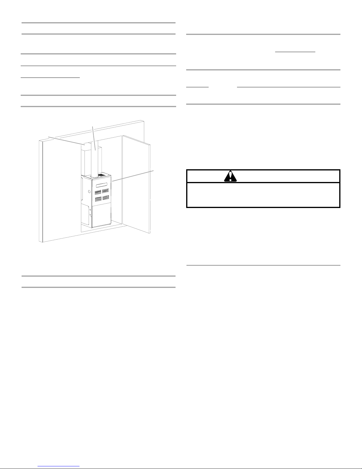
Installation Clearances and Accessibility
D
For installations above 7,000 ft (2,133.6 m), refer to your local
distributor for required kit(s).
Unobstructed front clearance of 24" (61 cm) for servicing is
recommended.
Clearances to Combustibles—in. (cm)
Vent Pipe
B1-Vent Single Wall
Connector Sides Front Back Top (Plenum)
1 (2.5) 6 (15.2) 1 (2.4) 3 (7.6) 0 1 (2.5)
NOTE: Top clearance for horizontal configuration is 1" (2.5 cm).
B
A
C
Manifold
Pressure
Pressure
High
Stage
Natural
0 to
Propane LPM-
NOTE: In Canada, gas furnaces are only certified to 4,500 ft
(1,371.6 m).
Contact your local distributor for a tabular listing of appropriate
manufacturer’s kits for propane gas and/or high altitude
installations. The indicated kits must be used to insure proper
furnace operation. All conversions must be performed by a
qualified installer or service agency.
7,000 ft
(2,133.6 m)
None #43 3.5"
W.C.
#55 10.0"
03B
W.C.
Low
Stage
1.9"
W.C.
6.0"
W.C.
Switch
ChangeGas Altitude Kit Orifice
None
None
Propane Gas Conversion
WARNING
Failure to follow these instructions can result in bodily
injury or death. Carefully read and follow all instructions
given in this section.
Goodman 53
E
A. Top clearance—1" (2.5 cm)
B. Vent pipe clearance—6" (15.2 cm)
for single wall connector, 1"
(2.5 cm) for B-1 vent
C. Back clearance—0"
D. Side clearance—1" (2.5 cm)
E. Front clearance—3" (7.6 cm)
High Altitude Installations
High Altitude Derate
IMPORTANT: The furnace will naturally derate itself with altitude.
Do not attempt to increase the firing rate by changing orifices or
increasing the manifold pressure. This can cause poor
combustion and equipment failure.
High altitude installations may require both a pressure switch and
an orifice change. These changes are necessary to compensate
for the natural reduction in the density of both the gas fuel and
the combustion air at higher altitude.
This unit is configured for Natural gas. The appropriate
manufacturer’s propane gas conversion kit must be applied for
propane gas installations.
Contact your local distributor for a tabular listing of appropriate
manufacturer’s kits for propane gas and/or high altitude
installations. The indicated kits must be used to insure safe and
proper furnace operation. All conversions must be performed by
a qualified installer or service agency.
Installation Configurations
Horizontal Installation
Line contact to framing is permitted when installed in the
horizontal configuration. Line contact is defined as the portion of
the cabinet that is formed by the intersection of the top and side.
IMPORTANT: Accessibility clearance, where greater, should take
precedence over minimum fire protection clearance.
A gas-fired furnace for installation in a residential garage must be
installed so that the ignition source and burners are located not
less than 18" (45.7 cm) above the floor and are protected or
located to prevent physical damage by vehicles.
A gas furnace must not be installed directly on carpeting, tile, or
other combustible materials other than wood flooring.
7
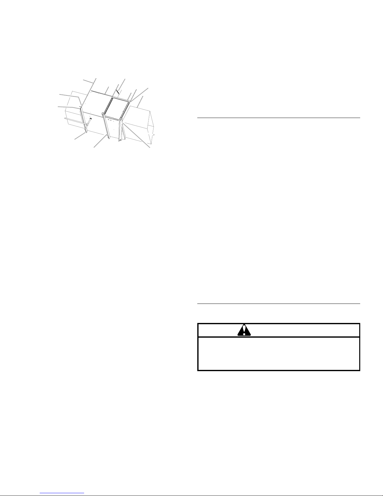
Furnace Suspension
If you are suspending the furnace from the rafters or joists, use a
³⁄₈" (1 cm) threaded rod and 2" x 2" x ³⁄₈" (5.1 cm x 5.1 cm x 1 cm)
angle iron as shown below. The length of the rod will depend on
the application and the clearances necessary.
Suspended Furnace
A
H
G
F
A.
³⁄₈
" (1 cm) diameter threaded
rod (6)
B. 8" (20.3 cm) minimum
clearance between center rod
and furnace cabinet to allow for
circulator blower removal.
C. Level furnace end to end, slight
forward tilt with front 0" to
(1.9 cm) below back.
³⁄₄
"
D. Tilt outward to allow for door and
E. Position as close as possible to
F. 2" x 2" x
G. Support nuts
H. Hold down nuts
B
C
DE
circulator blower removal.
blower deck to allow for circulator
blower removal.
1cm) angle iron (3)
³⁄₈
" (5.1 cm x 5.1 cm x
Existing Furnace Removal
NOTE: When an existing furnace is removed from a venting
system serving other appliances, the venting system may be too
large to properly vent the remaining attached appliances.
The following vent testing procedure is reproduced from the
American National Standard/National Standard of Canada for
Gas-Fired Central Furnaces ANSI Z21.47-Latest Edition, CSA-
2.3-Latest Edition Section 1.23.1. The following steps shall be
followed with each appliance connected to the venting system
placed in operation, while any other appliances connected to the
venting system are not in operation.
1. Seal any unused openings in the venting system.
2. Inspect the venting system for proper size and horizontal
pitch, as required by the National Fuel Gas Code, ANSI
Z223.1 or the CAN/CSA B149 Installation Codes and these
instructions. Determine that there is no blockage or
restriction, leakage, corrosion and other deficiencies which
could cause an unsafe condition.
3. In so far as practical, close all building doors and windows
and all doors between the space in which the appliance(s)
connected to the venting system are located and other
spaces of the building. Turn on clothes dryers and any
appliance not connected to the venting system. Turn on any
exhaust fans, such as range hoods and bathroom exhausts,
so they shall operate at maximum speed. Do not operate a
summer exhaust fan. Close fireplace dampers.
4. Follow the lighting instructions. Place the appliance being
inspected in operation. Adjust thermostat so appliance shall
operate continuously.
5. Test for draft hood equipped appliance spillage at the draft
hood relief opening after 5 minutes of main burner operation.
Use the flame of a match or candle.
6. After it has been determined that each appliance connected
to the venting system properly vents when tested as outlined
above, return doors, windows, exhaust fans, fireplace
dampers and any other gas burning appliance to their
previous conditions of use.
7. If improper venting is observed during any of the above tests,
the common venting system must be corrected.
Corrections must be in accordance with the latest edition of the
National Fuel Gas Code NFPA 54/ANSI Z223.1 and/or CAN/CSA
B149 Installation Codes.
If resizing is required on any portion of the venting system, use
the appropriate table in Appendix G in the latest edition of the
National Fuel Gas Code ANSI Z223.1 and/or CAN/CSA B149
Installation Codes.
Ductwork Requirements
■ Install all conditioned air plenums, ducts and air filters (if not
provided on the furnace) in accordance with NFPA 90B
Standard for the Installation of Warm Air Heating and AirConditioning Systems (latest edition).
■ The furnace is provided with flanges for the connection of the
plenum and ducts.
■ All air filters must be listed as Class 2 furnace air filters.
■ All ductwork must be made of materials and insulated to
meet local, state and national codes. Ductwork installed
outdoors must be sealed, weatherproof and kept from
physical damage. Caulking, flashing or other means of
adequately providing a permanent weather seal should be
used where duct penetrates a building or structure opening.
■ A closed return duct system must be used with the return
duct connected to the furnace.
■ Do not attach ductwork to the back of the furnace.
■ Flexible joints may be used for supply and return connections
to reduce noise transmission.
■ A connecting duct must be installed between the furnace and
the utility room wall to keep the blower from interfering with
combustion air or draft when a central return is used.
■ Do not use a room, closet or alcove as a return air chamber.
■ For models with airflow over 1,800 CFM, install a bottom
return, 2 side returns or 1 side and 1 bottom return.
Electrical Requirements
WARNING
To avoid the risk of injury, electrical shock or death, the
furnace must be electrically grounded in accordance with
local codes or, in their absence, with the latest edition of the
National Electric Code (NEC).
■ The furnace must be grounded and wired in accordance with
local codes or, in the absence of local codes, with the
National Electrical Code ANSI/NFPA No. 70 (latest edition).
■ In all instances, other than wiring for the thermostat, the
wiring to be done and any replacement of wire shall conform
with the temperature limitation for Type T wire (63°F [17ºC]
rise).
8
■ The line voltage supply should be routed through a readily
accessible disconnect located within sight of the furnace. A
junction box on the furnace side panel is provided for line
voltage connections. See the Wiring Connection Diagram in
the “Troubleshooting” section for specific connection
information.
■ Proper polarity of the supply connections (“HOT” and
“NEUTRAL”) must be observed to be sure that the control
system provides the damage avoidance intended.
Existing Venting Systems
When an existing furnace is removed or replaced, the original
venting system may no longer be sized to properly vent the
attached appliances. An improperly sized venting system can
result in the spilling of flue products into the living space, the
formation of condensate, leakage, etc. See the “Carbon
Monoxide Poisoning Hazard” for proper test procedure.
Gas Supply Requirements
This unit is equipped for use with Natural gas. A conversion kit is
required for use with propane. To order the correct conversion kit,
see your local distributor.
■ Gas supply piping should be installed in accordance with
local, state and national codes and the regulations of the
utility. Piping must be of adequate size to prevent undue
pressure drop. Consult the local utility or gas supplier for
complete details on special requirements for sizing gas
piping.
■ If local codes allow the use of a flexible gas appliance
connector, use a CSA design-certified outdoor flexible
stainless steel appliance connector or rigid gas supply line as
needed.
Venting Requirements
WARNING
Goodman 51
To avoid property damage, personal injury or death,
sufficient fresh air for proper combustion and ventilation
of flue gases must be supplied. Most homes require
outside air be supplied into the furnace area.
Improved construction and additional insulation in buildings have
reduced heat loss by reducing air infiltration and escape around
doors and windows. These changes have helped in reducing
heating/cooling costs but have created a problem supplying
combustion and ventilation air for gas-fired and other fuel
burning appliances. Appliances that pull air out of the house
(clothes dryers, exhaust fans, fireplaces, etc.) increase the
problem by starving appliances for air.
House depressurization can cause back drafting or improper
combustion of gas-fired appliances, thereby exposing the
building occupants to gas combustion products that could
include carbon monoxide.
If this furnace is to be installed in the same space with other gas
appliances, such as a water heater, ensure there is an adequate
supply of combustion and ventilation air for the other appliances.
Refer to the latest edition of the National Fuel Gas Code NFPA
54/ ANSI Z223.1 (Section 5.3), or CAN/CSA B149 Installation
Codes (Sections 7.2, 7.3, or 7.4), or applicable provisions of the
local building codes for determining the combustion air
requirements for the appliances.
This furnace must use indoor air for combustion. It cannot be
installed as a direct vent (for example, sealed combustion)
furnace. Most homes will require outside air be supplied to the
furnace area by means of ventilation grilles or ducts connecting
directly to the outdoors or spaces open to the outdoors such as
attics or crawl spaces.
WARNING:
CARBON MONOXIDE POISONING HAZARD
Failure to follow the steps outlined below for each
appliance connected to the venting system being
placed into operation could result in carbon monoxide
poisoning or death.
The following steps shall be followed for each appliance
connected to the venting system being placed into operation,
while all other appliances connected to the venting system are
not in operation:
1. Seal any unused openings in the venting system.
2. Inspect the venting system for proper size and horizontal
pitch, as required in the National Fuel Gas Code,
ANSI Z223.1/NFPA 54 or the CSA B149.1, Natural Gas and
Propane Installation Codes and these instructions.
Determine that there is no blockage or restriction, leakage,
corrosion and other deficiencies which could cause an
unsafe condition.
3. As far as practical, close all building doors and windows
and all doors between the space in which the appliance(s)
connected to the venting system are located and other
spaces of the building.
4. Close fireplace dampers.
5. Turn on clothes dryers and any appliance not connected to
the venting system. Turn on any exhaust fans, such as
range hoods and bathroom exhausts, so they are operating
at maximum speed. Do not operate a summer exhaust fan.
6. Follow the lighting instructions. Place the appliance being
inspected into operation. Adjust the thermostat so
appliance is operating continuously.
7. Test for spillage from draft hood equipped appliances at the
draft hood relief opening after 5 minutes of main burner
operation. Use the flame of a match or candle.
8. If improper venting is observed during any of the above
tests, the venting system must be corrected in accordance
with the National Fuel Gas Code, ANSI Z223.1/NFPA 54
and/or CSA B149.1, Natural Gas and Propane Installation
Codes.
9. After it has been determined that each appliance connected
to the venting system properly vents when tested as
outlined above, return doors, windows, exhaust fans,
fireplace dampers and any other gas-fired burning
appliances to their previous conditions of use.
9
INSTALLATION INSTRUCTIONS
Inspect Shipment
This furnace is shipped in one package, completely assembled
and wired. The indoor thermostat and accessories are shipped in
a separate carton when ordered.
■ Check the furnace rating plate to confirm specifications are
as ordered.
■ Upon receipt of the furnace, inspect it for possible shipping
damage. Examine the furnace inside the carton if the carton
is damaged.
■ If damage is found, it should be noted on the carrier’s freight
bill. Damage claims should be filed with the carrier
immediately. Claims of shortages should be filed with the
seller within 5 days.
NOTE: If any damages are discovered and reported to the carrier,
do not install the furnace, because your claim may be denied.
Plan Vent System
Category I Venting—Vertical Venting
WARNING
Goodman 66
To prevent possible personal injury or death due to
asphyxiation, this furnace must be Category I vented.
Do not vent using Category III venting.
Provisions must be made for venting combustion
products outdoors through a proper venting system.
The length of flue pipe could be a limiting factor in
locating the furnace.
The minimum vent diameter for the Category I venting system is
as shown in the Minimum Vent chart.
Minimum Vent
Model Upflow Counterflow
45 4" (10.2 cm) 4" (10.2 cm)
70 4" (10.2 cm) 4" (10.2 cm)
90 4" (10.2 cm) 4" (10.2 cm)
115 5" (12.7 cm) 5" (12.7 cm)
140 5" (12.7 cm) N/A
Under some conditions, larger vents than those shown in the
Minimum Vent chart may be required or allowed. When an
existing furnace is removed from a venting system serving other
appliances, the venting system may be too large to properly vent
the remaining attached appliances.
Upflow or horizontal units are shipped with the induced draft
blower discharging from the top of the furnace. (“Top” is as
viewed for an upflow installation.) The induced draft blower can
be rotated 90 degrees for Category I venting. For horizontal
installations, a 4" (10.2 cm) single-wall pipe can be used to
extend the induced draft blower outlet ¹⁄₂" (1.3 cm) beyond the
furnace cabinet. This product is not designed for
counterclockwise induced draft blower rotation.
Vent the furnace in accordance with the National Fuel Gas Code
NFPA 54/ANSI Z223.1—latest edition. In Canada, vent the
furnace in accordance with the National Standard of Canada,
CAN/CSA B149.1 and CAN/CSA B149.2—latest editions and
amendments.
Category I Venting is venting at a non-positive pressure. A
furnace vented as Category I is considered a fan-assisted
appliance. The vent system does not have to be “gas tight.”
NOTE: Single-stage gas furnaces with induced draft blowers
draw products of combustion through a heat exchanger allowing,
in some instances, common venting with natural draft appliances
(for example, water heaters).
All installations must be vented in accordance with National Fuel
Gas Code NFPA 54/ANSI Z223.1—latest edition. In Canada, the
furnaces must be vented in accordance with the National
Standard of Canada, CAN/CSA B149.1 and CAN/CSA B149.2—
latest editions and amendments.
NOTE: The vertical height of the Category I venting system must
be at least as great as the horizontal length of the venting system.
WARNING
To prevent possible personal injury or death, due to
asphyxiation, common venting with other manufacturer's
induced draft appliances is not allowed.
Goodman 67
Venting
NOTE: This furnace is not design certified to be horizontally
vented.
1. Disconnect electrical power from the furnace.
2. Disconnect the induced draft blower power leads, flue pipe
and pressure switch tubing.
3. Remove the round cutout from the right-hand side of the
wrapper.
4. Remove and save the 4 screws that fasten the induced draft
blower to the flue collector box.
5. Remove and save the 3 screws that hold the chimney
assembly to the induced draft blower.
6. Remove and save the 4 screws that fasten the chimney top to
the chimney bottom.
7. Remove the chimney transition bottom from the transition
bottom kit.
8. Install the chimney top with the 4 screws retained from Step
6 onto the new chimney transition bottom from the transition
bottom kit.
9. Install the chimney assembly with the 3 screws retained from
Step 5 onto the induced draft blower.
10. Reinstall the induced draft blower rotating it 90 degrees
clockwise from the original upflow configuration using the
4 screws retained in Step 3. Ensure the gasket located
between the induced draft blower and the collector box is
rotated accordingly.
10
11. Reconnect the induced draft blower power leads.
C
D
E
F
G
H
I
J
K
NOTE: If the wires are not long enough, pull extra wire from
the wire bundle in the blower compartment.
12. Reconnect the flue pipe and the pressure switch tubing.
Ensure that all wires and the pressure switch tubing are at
least 1" (2.5 cm) from the flue pipe, or any other hot surface.
13. Reconnect electrical power to the furnace.
Counterflow units are shipped with the inducted draft blower
discharging from the top (as viewed for a counterflow installation)
of the furnace.
Vent the furnace in accordance with the National Fuel Gas Code
NFPA 54/ANSI Z223.1—latest edition. In Canada, vent the
furnace in accordance with the National Standard of Canada,
CAN/CSA B149.1 AND CAN/CSA B149.2—latest editions and
amendments.
AB
R
Q
P
WARNING
Never allow the products of combustion, including carbon
monoxide, to enter the return ductwork or circulation air
supply.
Goodman 68
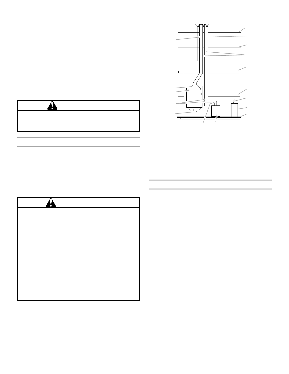
Category I Furnaces Only—Exterior Masonry Chimneys
An exterior masonry chimney is defined as a “Masonry chimney
exposed to the outdoors on one or more sides below the roof
line.” The ability to use a clay-lined masonry chimney depends on
a parameter not associated with interior chimneys. This variable
is the geographic location of the installation. Researchers have
discovered that the winter design temperatures have a direct
impact on the suitability of this type of venting. In most situations,
the existing masonry chimneys will require a properly-sized
metallic liner.
WARNING
Possiblility of property damage, personal injury or death.
Damaging condensation can occur inside masonry
chimneys when a single fan-assisted Category I appliance
(80% AFUE furnace) is vented without adequate dilution
air. Do not connect an 80% furnace to a masonry chimney
unless the furnace is common vented with a draft hood
equipped appliance or the chimney is lined with a metal
liner or Type B metal vent. All installations using masonry
chimneys must be sized in accordance with the
appropriate venting tables. If an 80% furnace is common
vented with a draft hood equipped appliance, the potential
for condensation damage may still exist with extremely
cold conditons, long vent connectors, exterior chimneys
or any combination of these conditions. The risk of
condensation damage is best avoided by using the
masonry chimney as a pathway for properly-sized metal
liner or Type B metal vent.
Goodman 69
O
N
L
M
A. Crown
B. Wash
C. Roof line
D. Clay tile size: 8" x 8" x
12" (24.3 cm x 24.3 cm
x 30.5 cm) (each x 24"
[61 cm] length)
E. Attic floor
F.
¹⁄₂
" to 1 " (1.3 cm to
2.5 cm) air space
G. Second floor
H. First floor
I. Water heater vent
connector
J. Natural draft water
heater
K. Basement floor
L. Fan-assisted
forced air furnace
M. Forced air furnace
vent connector
N. Clean out
O. Breech
P. D am p e r
Q. Throat
R. Clay tile size:
generally 12" x 12"
(30.5 cm x 30.5 cm)
(24" [61 cm] length)
Checklist Summary
This checklist serves as a summary of the items to be checked
before venting an 80+ furnace into a masonry chimney. In
addition, we recommend that a qualified serviceman use this
checklist to perform a yearly inspection of the furnace venting
system.
This checklist is only a summary. For detailed information on
each of the procedures mentioned, see the paragraph referenced
with each item.
This inspection is based upon a draft topical report, “Masonry
Chimney Inspection and Relining,” issued by the Gas Research
Institute. While not yet finalized, we believe this report represents
the best information on this subject which is currently available.
11
 Loading...