

Whirlpool WFCT, WGFDT Installation Instructions Manual
90+ MULTIPOSITIONAL GAS FURNACE
INSTALLATION INSTRUCTIONS
Table of Contents
GAS FURNACE SAFETY................................................................1
INSTALLATION REQUIREMENTS................................................3
Tools and Parts ............................................................................3
Location Requirements................................................................4
Installation Configurations ...........................................................5
Ductwork Requirements ..............................................................5
Electrical Requirements ...............................................................5
Gas Supply Requirements...........................................................5
Venting Requirements..................................................................5
INSTALLATION INSTRUCTIONS..................................................7
Inspect Shipment.........................................................................7
Plan Vent System.........................................................................8
Determine Vent Pipe Direction.....................................................9
Connect Venting.........................................................................16
Install Condensate Disposal ......................................................17
Connection to Pressure Switch .................................................20
GAS FURNACE SAFETY
Install Ductwork..........................................................................21
Filter Specifications....................................................................21
Make Electrical Connections .....................................................22
Make Gas Connections..............................................................22
Check the Furnace Input Rate (if required)................................23
Adjust the Furnace Input Rate (if required) ................................23
Complete Installation..................................................................24
Shut Down the Furnace .............................................................25
SEQUENCE OF OPERATION ......................................................25
Heating .......................................................................................25
Fan On........................................................................................25
Cooling .......................................................................................25
CONTROLS ...................................................................................26
TROUBLESHOOTING ..................................................................27
ASSISTANCE OR SERVICE.........................................................30
Accessories ................................................................................30
Your safety and the safety of others are very important.
We have provided many important safety messages in this manual and on your appliance. Always read and obey all safety
messages.
This is the safety alert symbol.
This symbol alerts you to potential hazards that can kill or hurt you and others.
All safety messages will follow the safety alert symbol and either the word “DANGER” or “WARNING.”
These words mean:
You can be killed or seriously injured if you don't immediately
DANGER
WARNING
All safety messages will tell you what the potential hazard is, tell you how to reduce the chance of injury, and tell you what can
happen if the instructions are not followed.
Whirlpool® and Whirlpool Gold
Models WFCT, WGFDT
47861B008
®
follow instructions.
can be killed or seriously injured if you don't
You
instructions.
Whirlpool® Home Cooling and Heating
14610 Breakers Drive
Jacksonville, FL 32258
follow
IMPORTANT SAFETY INSTRUCTIONS
Use only with type of gas approved for this furnace.
■
Refer to the furnace rating plate.
Install this furnace only in a location and position
■
as specified in the “Location Requirements” section
of these instructions.
Provide adequate combustion and ventilation air to
■
the furnace space as specified in the “Venting
Requirements” section of these instructions.
■
Combustion products must be discharged outdoors.
Connect this furnace to an approved vent system
only, as specified in the “Venting Requirements”
section of these instructions.
Never test for gas leaks with an open flame. Use a
■
commercially available soap solution made
specifically for the detection of leaks to check all
connections, as specified in the “Make Gas
Connections” section of these instructions.
Adequate clearance must be provided around the
■
vent-air intake terminals.
Always install furnace to operate within the furnace’s
■
intended temperature-rise range with a duct system
which has an external static pressure within the
allowable range, as specified in the “Complete
Installation” section of these instructions. See
furnace rating plate.
■
When a furnace is installed so that supply ducts
carry air circulated by the furnace to areas outside
the space containing the furnace, the return air
shall also be handled by duct(s) sealed to the
furnace casing and terminating outside the space
containing the furnace.
A gas-fired furnace for installation in a residential
■
garage must be installed as specified in the
“Location Requirements” section of these
instructions.
■
The furnace is not to be used for temporary heating
of buildings or structures under construction.
The furnace shall be installed so the electrical
■
components are protected from water.
■ Furnaces for indoor installation on combustible
flooring shall not be installed directly on carpeting,
tile or other combustible material other than wood
flooring.
SAVE THESE INSTRUCTIONS
WARNING:
FIRE OR EXPLOSION HAZARD
Failure to follow safety warnings exactly could result in serious injury, death or property
damage.
— Do not store or use gasoline or other flammable vapors and liquids in the vicinity of this or
any other appliance.
— WHAT TO DO IF YOU SMELL GAS
• Do not try to light any appliance.
• Do not touch any electrical switch; do not use any phone in your building.
• Leave the building immediately.
• Immediately call your gas supplier from a neighbor’s phone. Follow the gas supplier’s
instructions.
• If you cannot reach your gas supplier, call the fire department.
— Installation and service must be performed by a qualified installer, service agency or the gas
supplier.
2
WARNING: Gas leaks cannot always be detected by smell.
Gas suppliers recommend that you use a gas detector approved by UL or CSA.
For more information, contact your gas supplier.
If a gas leak is detected, follow the “What to do if you smell gas” instructions.
The California Safe Drinking Water and Toxic Enforcement Act requires the Governor of California to publish a list of substances
known to the State of California to cause cancer, birth defects, or other reproductive harm, and requires businesses to warn of
potential exposure to such substances.
WARNING: This product contains a chemical known to the State of California to cause cancer, birth defects, or other
reproductive harm.
This appliance can cause low-level exposure to some of the substances listed, including benzene, formaldehyde, carbon
monoxide, toluene, and soot.
ADDITIONAL SAFETY INFORMATION
In the State of Massachusetts, the following installation instructions apply:
■ Installations and repairs must be performed by a qualified or licensed contractor, plumber, or gasfitter qualified or licensed by
the State of Massachusetts.
■ If using a ball valve, it shall be a T-handle type.
■ A flexible gas connector, when used, must not exceed 3 feet.
INSTALLATION REQUIREMENTS
These instructions are intended as a general guide only for use by
qualified persons and do not supersede any national or local
codes in any way. Compliance with all local, state, or national
codes pertaining to this type of equipment should be determined
prior to installation.
Read this entire instruction manual, as well as the instructions
supplied in separate equipment, before starting the installation.
The installation of the furnace, wiring, warm air ducts, venting,
etc. must conform to the requirements of the National Fire
Protection Association; the National Fuel Gas Code, ANSI
Z223.1/NFPA No. 54 (latest edition) and the National Electrical
Code, ANSI/NFPA No. 70 (latest edition) in the United States, and
any state laws, local ordinances (including plumbing or
wastewater codes), or local gas utility requirements.
Tools and Parts
Gather the required tools before starting installation. Read and
follow the instructions provided with any tools listed here.
Too ls n eeded
■ Pipe wrench
■ Screwdriver
■ Tape m easu re
■ Thread sealant
■ Level
■ Noncorrosive leak check
solution
■ Tes t ga ug e wi th ¹⁄₈" (3.2 mm)
NPT connection (for measuring
gas supply pressure)
■ Allen wrench
Local authorities having jurisdiction should be consulted before
installation is made. Such applicable regulations or requirements
take precedence over the general instructions in this manual.
This furnace design is certified by CSA International as a
Category IV furnace in compliance with the latest edition of
American National Standard Z21.47/CSA Standard 2.3 for GasFired Central Furnaces, for operation with Natural gas or
propane. Consult the rating plate on the furnace for gas type
before installing.
Parts needed
Check local codes and with gas supplier. Check existing gas
supply, electrical supply, and venting, and read “Ductwork
Requirements,” “Electrical Requirements,” “Gas Supply
Requirements,” “Venting Requirements” and “Installation
Configurations” before purchasing parts.
Parts supplied
■ Inlet air restrictor plate
■ Flue pipe screen
■ Condensate disposal kit
3
Location Requirements
WARNING
Explosion Hazard
Keep flammable materials and vapors, such as
gasoline, away from furnace.
Place furnace so that burners are at least 18 inches
(46 cm) above the floor for a garage installation.
Failure to follow these instructions can result in death,
explosion, or fire.
WARNING
■ To avoid property damage caused by condensate drain
blockage, install a field-fabricated auxiliary drain pan with a
separate drain line to the outside under the entire furnace and
drain system. Install according to local codes.
■ All models are suitable for closet or utility room installation.
Utility room installation requires:
A door opening large enough for the widest part of the
furnace.
A door opening large enough to remove/replace any other
appliance located in the utility room, such as a water heater.
Any other appliances arranged so that each appliance can be
removed/replaced without disturbing the furnace.
■ In a residential garage, a gas-fired furnace must be installed
so the burner(s) and the ignition source are located not less
than 18" (45.7 cm) above the floor. The furnace is to be
located or protected to avoid physical damage by vehicles.
■ Furnaces may be installed as suspended units in the
horizontal position. These furnaces are not designed for
direct attachment of suspension rods to the furnace casing.
See “installation Configurations.”
■ If the furnace is to be installed in an attic or other insulated
space, it must be kept free and clear of insulating materials.
■ Furnaces may be installed as upflow or horizontal furnaces.
When the furnace is installed horizontally, secure the furnace
door by installing a sheet metal screw through the side and
door on the upper left-hand side of the furnace.
Explosion Hazard
Do not install this furnace in a mobile home.
Doing so can result in death, explosion, fire, or
carbon monoxide poisoning.
IMPORTANT: Do not use the furnace as a heater in a building
under construction. The furnace can be severely damaged due to
the abnormal environment caused by construction. Chlorides
from sources such as paint, stain, or varnish; tile and counter
cements; adhesives; and foam insulation are abundant in a
structure under construction and can be highly corrosive. Low
return air temperature can cause condensation in the furnace and
other damage that can shorten the life of the furnace.
■ The condensate system must not be exposed to
temperatures below 32°F (0ºC). Insulating condensate
system in areas exposed to temperatures below 32ºF (0ºC) is
necessary.
■ The furnace is suitable for installation in buildings
constructed on site. The furnace should be centralized in
respect to the heat distribution system as much as
practicable.
Installation Clearances
■ A 2" (5.1 cm) minimum clearance is required in front for air
openings into the combustion chamber.
■ All servicing and cleaning of the furnace can be performed
from the front. If installed in a closet or utility room, provide
24" (61 cm) clearance in front for service if the door to the
room is not in line with the front of the furnace. Where
servicing clearances are greater than clearances to
combustibles, servicing clearances take precedence.
Minimum Clearance to Combustibles Chart
Upflow Horizontal
Unit Sides 0" 0"
Rear of Unit 0" 0"
Front of Unit 2" (5.1 cm) 18" (45.7 cm)
Flue Pipe 0" 0"
Plenum Top (upflow) 1" (2.5 cm) 1" (2.5 cm)
Supply Duct (counterflow) 1" (2.5 cm) 1" (2.5 cm)
4
High Altitude Installations
■ This furnace is approved for operation at altitudes from 0 to
4,500 ft (0 to 1,371.6 m) above sea level without any required
modifications.
■ From 4,500 to 7,500 ft, (1,371.6 m to 2,286 m) the gas
manifold pressure needs to be adjusted according to the
information shown in the Manifold Pressure vs. Altitude
Chart.
IMPORTANT:
For installations above 7,500 ft (2,286 m), the furnace input rate is
to be reduced according to the requirements of the National Fuel
Gas Code (ANSI Z223.1/NFPA 54, latest edition), at the rate of
4 percent for each 1,000 ft (304.8 m) above sea level.
The furnace is not recommended for installation above 10,000 ft
(3,048 m).
Electrical Requirements
WARNING
Electrical Shock Hazard
Electrically ground furnace.
Connect ground wire to green ground screw.
Failure to do so can result in death or electrical shock.
Installation Configurations
IMPORTANT: To ensure access to parts for servicing, install the
furnace so that the burner and blower access panels are readily
accessible.
Ductwork Requirements
■ Install all conditioned air plenums, ducts and air filters (if not
provided on the furnace) in accordance with NFPA 90B
Standard for the Installation of Warm Air Heating and AirConditioning Systems (latest edition).
■ The furnace is provided with flanges for the connection of the
plenum and ducts.
■ All air filters must be listed as Class 2 furnace air filters.
■ All ductwork must be made of materials and insulated to
meet local, state and national codes. Ductwork installed
outdoors must be sealed, weatherproofed and protected
against physical damage. Caulking, flashing or other means
of adequately providing a permanent weather seal should be
used where duct penetrates a building or structure opening.
■ The furnace must be grounded and wired in accordance with
local codes or, in the absence of local codes, with the
National Electrical Code ANSI/NFPA No. 70 (latest edition).
■ In all instances, other than wiring for the thermostat, the
wiring to be done and any replacement of wire shall conform
with the temperature limitation for Type T wire (63°F rise).
■ The line voltage supply should be routed through a readily
accessible disconnect located within sight of the furnace. A
junction box on the furnace side panel is provided for line
voltage connections. See the furnace wiring diagram for
specific connection information.
■ Proper polarity of the supply connections (“HOT” and
“NEUTRAL”) must be observed to be sure that safety controls
provide the protection intended.
Gas Supply Requirements
This furnace is equipped for use with Natural gas. A conversion
kit is required for use with propane. To order the correct
conversion kit, see “Accessories.”
■ Gas supply piping should be installed in accordance with
local, state and national codes and the regulations of the
utility. Piping must be of adequate size to avoid undue
pressure drop. Consult the local utility or gas supplier for
complete details on special requirements for sizing gas
piping.
■ If local codes allow the use of a flexible gas appliance
connector, use a CSA design-certified outdoor flexible
stainless steel appliance connector or rigid gas supply line as
needed. Do not use a connector which has previously
serviced another gas appliance.
Venting Requirements
Adequate provisions for combustion air and ventilation of furnace
must be made. Refer to Section 5.3, “Air for Combustion and
Ventilation,” of the National Fuel Gas Code, ANSI Z223.1/NFPA54
(latest edition), or applicable provisions of the local building
codes.
5
Existing Venting Systems
Venting Options
When an existing furnace is removed or replaced, the original
venting system may no longer be sized to properly vent the
attached appliances. An improperly sized venting system can
result in spillage of flue products into the living space, the
formation of condensate, leakage, etc. See the “Carbon
Monoxide Poisoning Hazard” for proper test procedure.
WARNING:
CARBON MONOXIDE POISONING HAZARD
Failure to follow the steps outlined below for each
appliance connected to the venting system being
placed into operation could result in carbon monoxide
poisoning or death.
The following steps shall be followed for each appliance
connected to the venting system being placed into operation,
while all other appliances connected to the venting system are
not in operation:
1. Seal any unused openings in the venting system.
2. Inspect the venting system for proper size and horizontal
pitch, as required in the National Fuel Gas Code,
ANSI Z223.1/NFPA 54 or the CSA B149.1, Natural Gas and
Propane Installation Codes and these instructions.
Determine that there is no blockage or restriction, leakage,
corrosion and other deficiencies which could cause an
unsafe condition.
3. As far as practical, close all building doors and windows
and all doors between the space in which the appliance(s)
connected to the venting system are located and other
spaces of the building.
4. Close fireplace dampers.
5. Turn on clothes dryers and any appliance not connected to
the venting system. Turn on any exhaust fans, such as
range hoods and bathroom exhausts, so they are operating
at maximum speed. Do not operate a summer exhaust fan.
6. Follow the lighting instructions. Place the appliance being
inspected into operation. Adjust the thermostat so
appliance is operating continuously.
7. Test for spillage from draft hood equipped appliances at the
draft hood relief opening after 5 minutes of main burner
operation. Use the flame of a match or candle.
8. If improper venting is observed during any of the above
tests, the venting system must be corrected in accordance
with the National Fuel Gas Code, ANSI Z223.1/NFPA 54
and/or CSA B149.1, Natural Gas and Propane Installation
Codes.
9. After it has been determined that each appliance connected
to the venting system properly vents when tested as
outlined above, return doors, windows, exhaust fans,
fireplace dampers and any other gas-fired burning
appliances to their previous conditions of use.
The furnace can be installed as either direct vent or nondirect
vent furnaces.
For either type of installation, special venting considerations
must be followed. See “Determine Vent Pipe Direction” section
for the type of furnace and venting being installed.
Direct Vent
A direct vent (two pipe) installation requires that all the air
necessary for combustion be supplied from outside the dwelling
through an air intake pipe.
■ All vents passing through floors, ceilings, and walls must be
installed in accordance with National Fuel Gas Code, ANSI
Z223.1/NFPA 54 (latest edition). In all applications where the
flue pipe is run through an unconditioned space, ¹⁄₂" (1.3 cm)
insulation must be used over the pipe. In extremely cold
climates, ³⁄₄" (1.9 cm) insulation is recommended.
Nondirect Vent
A nondirect vent (one pipe) installation uses air from inside the
dwelling for combustion.
■ The furnace is shipped with the air inlet pipe terminated to the
top panel for either inside or outside combustion air. An inlet
air restrictor plate is supplied with this furnace and can be
found in the plastic bag containing these Installation
Instructions and the User’s Information Manual.
■ For installations using inside air for combustion (nondirect
vent), attach a 90° elbow (not supplied) to the inlet coupler
and install the restrictor plate inside the elbow (see
“Nondirect Vent Installation”).
Inlet Air Restrictor Plate
■ A 2" (5.1 cm) restrictor plate is supplied with the 40, 60, 80
and 100k Btu/h models. A 3" (7.6 cm) restrictor plate is
supplied with the 125k Btu/h model.
In horizontal applications, the restrictor plate must be
secured to the inlet collar by inserting a field supplied piece of
2" (5.1 cm) or 3" (7.6 cm) PVC pipe into the inlet collar after
the restrictor plate is installed. Use high temperature RTV
sealant to attach the PVC to the inlet collar.
Flue Pipe Screen
A flue pipe screen designed to keep objects out of the flue pipe is
included in the plastic bag.
In all installations, this screen should be installed at the
termination of the flue pipe.
Flue Pipe Screen
6
Unconfined Space
An unconfined space is defined as “a space whose volume is
more than 50 cu. ft (1.4 m
rating of all appliances installed in that space.”
When a furnace is installed in an unconfined space in a building,
it can be assumed that the infiltration will be sufficient to supply
the required air.
If the furnace is installed in a ventilated attic or crawl space, it is
assumed that the air infiltration is sufficient to supply the required
combustion air. However, in a building of unusually tight
construction, additional outdoor air should be provided.
3
) per 1,000 Btu/h of the combined input
Confined Space
A confined space is defined as “a space whose volume is less
than 50 cu. ft (1.4 m3) per 1,000 Btu/h of the combined input
rating of all appliances installed in that space.” Use “Direct Vent”
method. See “Plan Vent System.”
Contaminated Combustion Air
Excessive exposure to contaminated combustion air will result in
performance related problems. The recommended source of
combustion air is outdoor air.
Outdoor air as the source of combustion air
If the furnace is installed in a confined space, it is recommended
that the necessary combustion air come from the outdoors by
way of an attic, crawl space, air duct, or direct opening.
Outdoor air is required as the source of combustion air when the
indoor air is contaminated with chemical substances and in the
following types of installations:
■ Furnaces installed in commercial buildings
■ Furnaces installed in buildings with indoor pools
■ Furnaces installed in hobby or craft rooms
■ Furnaces installed near chemical storage areas
■ Furnaces installed in laundry rooms
■ Furnaces installed in hair salons
Indoor air as the source of combustion air
Indoor air as the source of combustion air is acceptable in most
applications if the following guidelines are met:
■ All provisions for indoor combustion air must meet the
requirements for combustion air indicated in the National Fuel
Gas Code, ANSI Z223.1/NFPA 54 (latest edition), and/or any
applicable local codes.
■ If indoor combustion air is used, the air supply to the furnace
should not be exposed to the following substances:
Permanent wave solutions
Chlorinated waxes and cleaners
Chlorine-based swimming pool chemicals
Water softening chemicals
Deicing salts or chemicals
Carbon tetrachloride
Halogen-type refrigerants
Cleaning solvents (such as perchloroethylene)
Printing inks, paint removers, varnishes, etc.
Cements and glues
Antistatic fabric softeners for clothes dryers
Masonry acid washing materials
Chlorinated laundry products
Hydrochloric acid
INSTALLATION INSTRUCTIONS
WARNING
Explosion Hazard
Furnace must be installed and serviced by a
qualified person.
Examples of a qualified person include:
licensed heating personnel,
authorized gas company personnel.
Read and follow all instructions provided for
installation, adjustment, service, alteration, or
maintenance.
Failure to follow these instructions can result in death,
explosion, fire, or carbon monoxide poisoning.
Inspect Shipment
WARNING
Excessive Weight Hazard
Use two or more people to move and install furnace.
Failure to do so can result in back or other injury.
This furnace is shipped in one package, completely assembled
and wired. The indoor thermostat and accessories are shipped in
a separate carton when ordered.
1. Check the furnace rating plate to confirm specifications are
as ordered.
2. Upon receipt of the furnace, inspect it for possible shipping
damage. Examine the furnace inside the carton if the carton
is damaged.
If damage is found, it should be noted on the carrier’s freight bill.
Damage claims should be filed with the carrier immediately.
Claims of shortages should be filed with the seller within 5 days.
NOTE: If any damages are discovered and reported to the carrier,
do not install the furnace, because your claim may be denied.
7

Plan Vent System
The high efficiency of this furnace is accomplished by the
removal of both sensible and latent heat from the flue gases. The
removal of latent heat results in the condensation of moisture in
the flue gases. This condensation occurs in the secondary heat
exchanger and in the vent system. Therefore, this furnace
requires special venting considerations, and the instructions
must be followed to ensure proper operation. All venting must be
in accordance with the codes having jurisdiction in the area and
these instructions.
IMPORTANT:
■ The venting system must be supported with mounting straps
to keep any weight load from being applied to the vent
blower. Horizontal vent pipe must be supported every 5 ft
(1.5 m) and vertical pipe should be supported every 10 ft
(3 m) to avoid sagging and provide rigid support.
■ This furnace must not be connected to any Type B, BW, or
L vent or vent connector and must not be connected to any
portion of a factory-built or masonry chimney.
■ This furnace is not to be common vented with any other
appliance. The vent pipe must not be connected to a
chimney flue serving a separate appliance designed to burn
solid fuel.
Materials
■ All pipe, fittings, primer, and solvent cement must conform
with American National Standard Institute and the American
Society for Testing and Materials (ANSI/ASTM) standards.
The solvent shall be free flowing and contain no lumps,
undissolved particles, or any foreign matter that adversely
affects the joint strength or chemical resistance of the
cement. The cement shall show no gelatinization,
stratification, or separation that cannot be removed by
stirring. See “Piping and Fitting Specifications” for approved
piping and fitting materials.
Piping and Fitting Specifications
Piping and Fitting Material ASTM Specification
Schedule 40 PVC (Pipe) D1785
Schedule 40 PVC (Cellular Core Pipe) F891
Schedule 40 PVC (Fittings) D2466
SDR-26 (Pipe) D2241
Schedule 40 ABS (Pipe) D1527
Schedule 40 ABS (Fittings) D2468
Schedule 40 & 80 CPVC (Pipe) F441
ABS-DWV Drain Waste & Vent
(Pipe & Fittings)
PVC-DWV Drain Waste & Vent
(Pipe & Fittings)
■ The primers and solvents used must also meet ASTM
specifications. PVC primer is specified in ASTM F656. Use
PVC solvent as specified in ASTM D2564 and ABS solvent
cement as specified ASTM D2235. Low temperature solvent
cement is recommended. Metal or plastic strapping may be
used for vent pipe hangers.
■ When making ABS joints, pieces can be prepared with a
cleaner. When joining ABS to PVC materials, use PVC solvent
cement as specified in ASTM D3138.
■ Preferred fittings are DWV style or long sweep. Seal all joints
gas tight with appropriate cement. In areas where vent and air
intake pipes are exposed to abnormal stress or are subject to
damage, schedule 80 pipe should be used.
■ Use high temperature RTV silicone sealant to attach the air
intake pipe into the connector on the burner box so the air
intake pipe can be removed if service is required.
NOTE: Do not use cement.
D2661
D2665
Vent Pipe Size and Length
The vent pipe and air intake pipe (in direct vent installations) should be sized in accordance with the information found in the Vent Table
charts. One 90° elbow is equivalent to 5 ft (1.5 m) of pipe. Two 45° elbows are equivalent to one 90° elbow. The minimum length
certified for use with this furnace is 5 ft (1.5 m) and one elbow, not including the vent and air intake terminals.
Vent Table—40,000 to 80,000 Btu/h Models
Vent Pipe Length—ft (m) Minimum Pipe Diameter—in. (cm)
5 (1.5) 1¹⁄₂ (3.8) 1¹⁄₂ (3.8) 2 (5.1) 2 (5.1) 2 (5.1) 2 (5.1) 2 (5.1) 2 (5.1) 2 (5.1) 2 (5.1)
10 (3) 1¹⁄₂ (3.8) 2 (5.1) 2 (5.1) 2 (5.1) 2 (5.1) 2 (5.1) 2 (5.1) 2 (5.1) 2 (5.1) 2 (5.1)
20 (6.1) 2 (5.1) 2 (5.1) 2 (5.1) 2 (5.1) 2 (5.1) 2 (5.1) 2 (5.1) 2 (5.1) 2 (5.1) 2¹⁄₂ (6.4)
30 (9.1) 2 (5.1) 2 (5.1) 2 (5.1) 2 (5.1) 2 (5.1) 2 (5.1) 2 (5.1) 2¹⁄₂ (6.4) 2¹⁄₂ (6.4) 2¹⁄₂ (6.4)
40 (12.2) 2 (5.1) 2 (5.1) 2 (5.1) 2 (5.1) 2 (5.1) 2¹⁄₂ (6.4) 2¹⁄₂ (6.4) 2¹⁄₂ (6.4) 2¹⁄₂ (6.4) 2¹⁄₂ (6.4)
50 (15.2) 2 (5.1) 2 (5.1) 2¹⁄₂ (6.4) 2¹⁄₂ (6.4) 2¹⁄₂ (6.4) 2¹⁄₂ (6.4) 2¹⁄₂ (6.4) 2¹⁄₂ (6.4) 2¹⁄₂ (6.4) 3 (7.6)
60 (18.3) 2 (5.1) 2¹⁄₂ (6.4) 2¹⁄₂ (6.4) 2¹⁄₂ (6.4) 2¹⁄₂ (6.4) 2¹⁄₂ (6.4) 2¹⁄₂ (6.4) 3 (7.6) 3 (7.6) 3 (7.6)
70 (21.3) 2¹⁄₂ (6.4) 2¹⁄₂ (6.4) 2¹⁄₂ (6.4) 2¹⁄₂ (6.4) 2¹⁄₂ (6.4) 3 (7.6) 3 (7.6) 3 (7.6) 3 (7.6) NR
80 (24.4) 2¹⁄₂ (6.4) 2¹⁄₂ (6.4) 2¹⁄₂ (6.4) 3 (7.6) 3 (7.6) 3 (7.6) 3 (7.6) 3 (7.6) NR NR
90 (27.4) 2¹⁄₂ (6.4) 2¹⁄₂ (6.4) 3 (7.6) 3 (7.6) 3 (7.6) 3 (7.6) 3 (7.6) NR NR NR
Number of 90º Elbows 0 1 2 3 4 5 6 7 8 9
NR = Not Recommended
8
Vent Table—90,000 to 100,000 Btu/h Models
Vent Pipe Length—ft (m) Minimum Pipe Diameter—in. (cm)
5 (1.5) NR 2 (5.1) 2 (5.1) 2 (5.1) 2 (5.1) 2 (5.1) 2 (5.1) 2¹⁄₂ (6.4) 2¹⁄₂ (6.4) 2¹⁄₂ (6.4)
10 (3) 2 (5.1) 2 (5.1) 2 (5.1) 2 (5.1) 2 (5.1) 2 (5.1) 2¹⁄₂ (6.4) 2¹⁄₂ (6.4) 2¹⁄₂ (6.4) 2¹⁄₂ (6.4)
20 (6.1) 2 (5.1) 2 (5.1) 2 (5.1) 2 (5.1) 2 (5.1) 2¹⁄₂ (6.4) 2¹⁄₂ (6.4) 2¹⁄₂ (6.4) 2¹⁄₂ (6.4) 3" (7.6)
30 (9.1) 2 (5.1) 2 (5.1) 2 (5.1) 2¹⁄₂ (6.4) 2¹⁄₂ (6.4) 2¹⁄₂ (6.4) 2¹⁄₂ (6.4) 3 (7.6) 3 (7.6) 3 (7.6)
40 (12.2) 2 (5.1) 2 (5.1) 2¹⁄₂ (6.4) 2¹⁄₂ (6.4) 2¹⁄₂ (6.4) 3 (7.6) 3 (7.6) 3 (7.6) 3 (7.6) 3 (7.6)
50 (15.2) 2¹⁄₂ (6.4) 2¹⁄₂ (6.4) 2¹⁄₂ (6.4) 3 (7.6) 3 (7.6) 3 (7.6) 3 (7.6) 3 (7.6) 3 (7.6) NR
60 (18.3) 2¹⁄₂ (6.4) 3 (7.6) 3 (7.6) 3 (7.6) 3 (7.6) 3 (7.6) 3 (7.6) NR NR NR
70 (21.3) 3 (7.6) 3 (7.6) 3 (7.6) 3 (7.6) 3 (7.6) NR NR NR NR NR
80 (24.4) 3 (7.6)3 (7.6)3 (7.6)NRNRNRNRNRNRNR
90 (27.4) 3 (7.6)3 (7.6)NRNRNRNRNRNRNRNR
Number of 90° Elbows0 123456789
NR = Not Recommended
Vent Table—112,000 to 125,000 Btu/h Models
Vent Pipe Length—ft (m) Minimum Pipe Diameter—in. (cm)
5 (1.5) 2¹⁄₂ (6.4) 2¹⁄₂ (6.4) 2¹⁄₂ (6.4) 2¹⁄₂ (6.4) 2¹⁄₂ (6.4) 2¹⁄₂ (6.4) 2¹⁄₂ (6.4) 2¹⁄₂ (6.4) 2¹⁄₂ (6.4) 2¹⁄₂ (6.4)
10 (3) 2¹⁄₂ (6.4) 2¹⁄₂ (6.4) 2¹⁄₂ (6.4) 2¹⁄₂ (6.4) 2¹⁄₂ (6.4) 2¹⁄₂ (6.4) 2¹⁄₂ (6.4) 2¹⁄₂ (6.4) 2¹⁄₂ (6.4) 3 (7.6)
20 (6.1) 2¹⁄₂ (6.4) 2¹⁄₂ (6.4) 2¹⁄₂ (6.4) 2¹⁄₂ (6.4) 2¹⁄₂ (6.4) 2¹⁄₂ (6.4) 2¹⁄₂ (6.4) 3 (7.6) 3 (7.6) NR
30 (9.1) 2¹⁄₂ (6.4) 2¹⁄₂ (6.4) 2¹⁄₂ (6.4) 2¹⁄₂ (6.4) 2¹⁄₂ (6.4) 3 (7.6) 3 (7.6) NR NR NR
40 (12.2) 2¹⁄₂ (6.4) 2¹⁄₂ (6.4) 2¹⁄₂ (6.4) 2¹⁄₂ (6.4)3 (7.6)NRNRNRNRNR
50 (15.2) 2¹⁄₂ (6.4) 3 (7.6) 3 (7.6) NR NR NR NR NR NR NR
60 (18.3) 3 (7.6)3 (7.6)NRNRNRNRNRNRNRNR
Number of 90° Elbows0 123456789
NR = Not Recommended
In the event that the pipe length is in between the lengths listed in
the Vent Table, use the next larger length listed. For example, if a
length of pipe needed to install the furnace is 27 ft (8.2 m), use
the diameter values for the 30 ft (9.1 m) row in the tables.
For direct vent installations, if the vent and air intake pipe are not
equal in length and number of elbows, then determine the
minimum pipe diameter for both the vent and air intake. If the
results indicate different diameters, use the larger of the two for
both the vent and air intake.
NOTE: Under no circumstances should the vent and air intake
pipe size be different in diameter. See “Plan Vent System” for the
furnace model and type of installation.
Determine Vent Pipe Direction
The vent system of the furnace must be self-supporting and must not apply any weight load to the combustion blower.
Combustion Air Sources
There are 2 sources for combustion air:
1. From outside the building (Direct Vent)
2. From inside the building (Nondirect Vent)
Please read the information provided here about Vertical and
Horizontal Venting, then find and follow the instructions for your
venting configuration.
Vertical Venting
A vertical vent should extend through the roof a minimum of 24"
(5.1 cm) and not be obstructed a minimum of 10 ft (3 m) in any
direction.
Horizontal Venting
The vent terminal location shall comply with the National Fuel
Gas Code (ANSI Z223.1) or local requirements. For informational
purposes, the side wall terminal vent clearances are shown in the
Sidewall Vent Terminal Clearances tables.
9
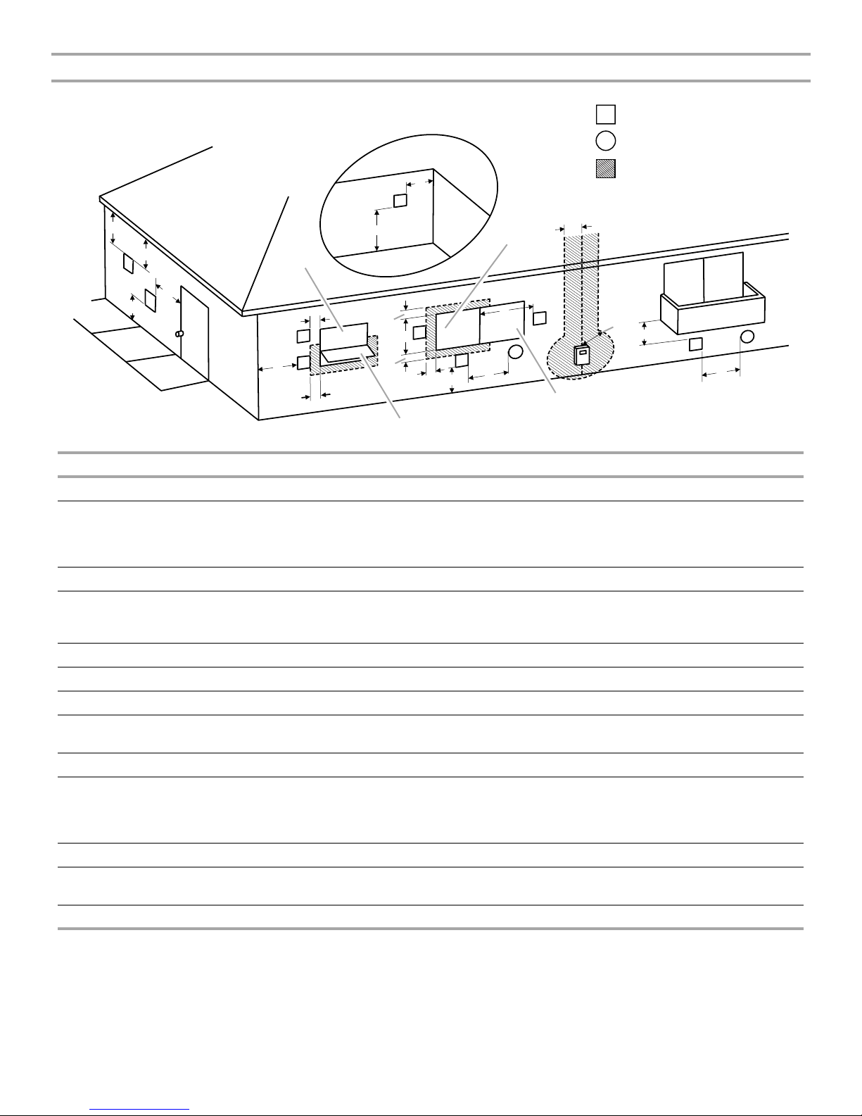
Sidewall Vent Terminal Clearances—Direct Vented Furnaces (Horizontal Venting)
Inside
Corner Detail
G
V
Vent Terminal
V
Air Supply Intake
X
Area Where Terminal Is
Not Permitted
D
E
V
B
V
L
Fixed
Closed
C
V
V
F
A
Operable
B
B
V
B
V
B
A
X
J
B
Operable
U.S. Installations
H
V
I
M
V
X
K
Fixed
Closed
1
A Clearance above grade, veranda, porch, deck, or balcony 12" (30.5 cm)
B Clearance to window or door that may be opened 6" (15.2 cm) for appliances less than 10,000 Btu/h, 9" (22.9 cm) for
appliances greater than 10,000 Btu/h, and less than or equal to
50,000 Btu/h, 12" (30.5 cm) for appliances greater than
50,000 Btu/h
C Clearance to permanently closed window *
D Vertical clearance to ventilated soffit located above the
*
terminal within a horizontal distance of 24" (61 cm) from the
center line of the terminal
E Clearance to unventilated soffit *
F Clearance to outside corner *
G Clearance to inside corner *
H Clearance to each side of center line extended above meter/
*
regulator assembly
I Clearance to service regulator vent outlet *
J Clearance to nonmechanical air supply inlet to building or
the combustion air inlet to any other appliance
6" (15.2 cm) for appliances less than or equal to 10,000 Btu/h, 9"
(22.9 cm) for appliances greater than 10,000 Btu/h, and less than
or equal to 50,000 Btu/h, 12" (30.5 cm) for appliances greater than
50,000 Btu/h
K Clearance to a mechanical air supply inlet 36" (91.4 cm) above if within 10 ft (3 m) horizontally
L Clearance above paved sidewalk or paved driveway located
*
on public property
M Clearance under veranda, porch, deck, or balcony *
1
In accordance with the current ANSI Z2223.1/NFPA 54, National Fuel Gas Code.
*Clearance in accordance with local installation codes and the requirements of the gas supplier and the manufacturer’s installation
instructions.
10
 Loading...