

Whirlpool WFCH Installation Instructions Manual
90 HORIZONTAL GAS FURNACE
INSTALLATION INSTRUCTIONS
Table of Contents
GAS FURNACE SAFETY................................................................1
INSTALLATION REQUIREMENTS................................................3
Tools and Parts ............................................................................3
Location Requirements................................................................3
Installation Configurations ...........................................................4
Airflow Conversion .......................................................................5
Duct Work Requirements.............................................................8
Electrical Requirements ...............................................................9
Gas Supply Requirements...........................................................9
Venting Requirements..................................................................9
INSTALLATION INSTRUCTIONS................................................10
Inspect Shipment.......................................................................10
Plan Vent System.......................................................................10
Determine Vent Pipe Direction...................................................12
GAS FURNACE SAFETY
Connect Venting.........................................................................14
Install Condensate Disposal.......................................................14
Install Duct Work ........................................................................15
Filter Specifications....................................................................15
Make Electrical Connections .....................................................16
Make Gas Connections..............................................................16
Check the Furnace Input Rate ...................................................17
Adjust the Furnace Input Rate ...................................................17
Complete Installation..................................................................18
Sequence of Operation ..............................................................19
Controls ......................................................................................20
TROUBLESHOOTING ..................................................................20
ASSISTANCE OR SERVICE.........................................................23
Accessories ................................................................................23
Your safety and the safety of others are very important.
We have provided many important safety messages in this manual and on your appliance. Always read and obey all
safety messages.
This is the safety alert symbol.
This symbol alerts you to potential hazards that can kill or hurt you and others.
All safety messages will follow the safety alert symbol and either the word “DANGER” or
“WARNING.” These words mean:
You can be killed or seriously injured if you don't
immediately follow instructions.
can be killed or seriously injured if you don't
You
follow instructions.
All safety messages will tell you what the potential hazard is, tell you how to reduce the chance of injury, and tell you
what can
Model WFCH
46889B003
happen if the instructions are not followed.
Whirlpool® Home Cooling and Heating
7901 S.W. 6th Court
Plantation, Florida 33324
IMPORTANT SAFETY INSTRUCTIONS
Use only with type of gas approved for this furnace.
■
Refer to the furnace rating plate.
Install this furnace only in a location and position
■
as specified in the Location Requirements section
of these instructions.
Provide adequate combustion and ventilation air to
■
the furnace space as specified in the “Venting
Requirements” section of these instructions.
■
Combustion products must be discharged outdoors.
Connect this furnace to an approved vent system
only, as specified in the “Venting Requirements”
section of these instructions.
Never test for gas leaks with an open flame. Use a
■
commercially available soap solution made specifically for the detection of leaks to check all connections, as specified in the “Make Gas Connections”
section of these instructions.
Adequate clearance must be provided around the
■
vent-air intake terminals.
Always install furnace to operate within the furnace’s
■
intended temperature-rise range with a duct system
which has an external static pressure within the
allowable range, as specified in the “Complete
Installation” section of these instructions. See
furnace rating plate.
■
When a furnace is installed so that supply ducts
carry air circulated by the furnace to areas outside
the space containing the furnace, the return air
shall also be handled by duct(s) sealed to the
furnace casing and terminating outside the space
containing the furnace.
A gas-fired furnace for installation in a residential
■
garage must be installed as specified in the
“Location Requirements” section of these
instructions.
■
The furnace is not to be used for temporary heating
of buildings or structures under construction.
The furnace shall be installed so the electrical
■
components are protected from water.
■
Furnaces for indoor installation on combustible
flooring shall not be installed directly on carpeting,
tile or other combustible material other than wood
flooring.
SAVE THESE INSTRUCTIONS
The California Safe Drinking Water and Toxic Enforcement Act requires the Governor of California to publish a list
of substances known to the State of California to cause cancer, birth defects, or other reproductive harm, and
requires businesses to warn of potential exposure to such substances.
WARNING: This product contains a chemical known to the State of California to cause cancer, birth defects, or
other reproductive harm.
This appliance can cause low-level exposure to some of the substances listed, including benzene, formaldehyde,
carbon monoxide, toluene, and soot.
ADDITIONAL SAFETY INFORMATION
In the State of Massachusetts, the following installation instructions apply:
■
Installations and repairs must be performed by a qualified or licensed contractor, plumber, or gasfitter qualified or
licensed by the State of Massachusetts.
■
If using a ball valve, it shall be a T-handle type.
■
A flexible gas connector, when used, must not exceed 3 feet.
2
INSTALLATION
REQUIREMENTS
These instructions are intended as a general guide only for use by
qualified persons and do not supersede any national or local
codes in any way. Compliance with all local, state, or national
codes pertaining to this type of equipment should be determined
prior to installation.
Read this entire instruction manual, as well as the instructions
supplied in separate equipment, before starting the installation.
The installation of the furnace, wiring, warm air ducts, venting,
etc. must conform to the requirements of the National Fire
Protection Association; the National Fuel Gas Code, ANSI
Z223.1/NFPA No. 54 (latest edition) and the National Electrical
Code, ANSI/NFPA No. 70 (latest edition) in the United States, and
any state laws, local ordinances (including plumbing or
wastewater codes), or local gas utility requirements. Local
authorities having jurisdiction should be consulted before
installation is made. Such applicable regulations or requirements
take precedence over the general instructions in this manual.
This furnace design is certified by CSA International as a
Category IV furnace in compliance with the latest edition of
American National Standard Z21.47/CSA Standard 2.3 for GasFired Central Furnaces, for operation with natural gas or propane.
Consult the rating plate on the furnace for gas type before
installing.
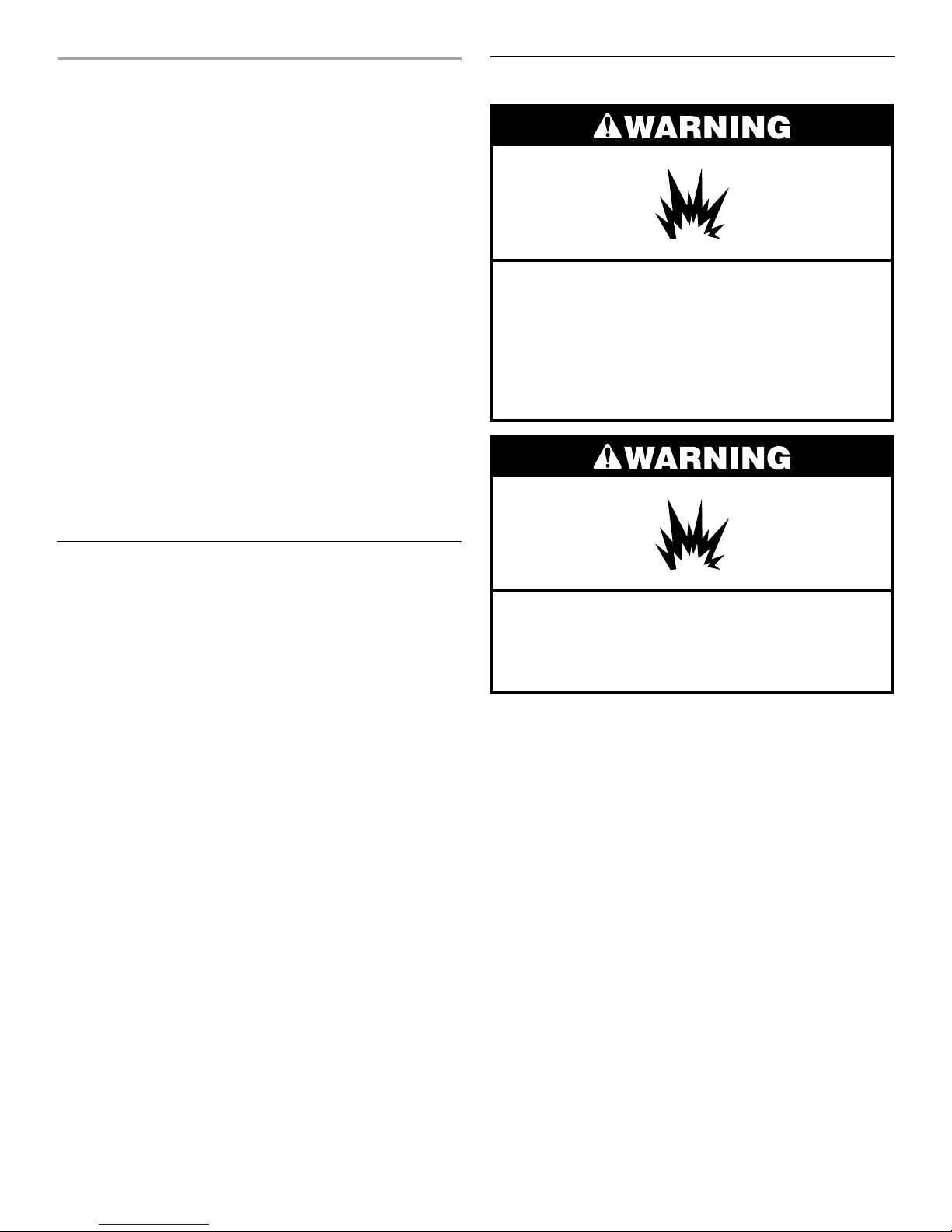
Location Requirements
Explosion Hazard
Keep flammable materials and vapors, such as
gasoline, away from furnace.
Place furnace so that burners are at least 18 inches
(46 cm) above the floor for a garage installation.
Failure to follow these instructions can result in death,
explosion, or fire.
Tools and Parts
Assemble the required tools before starting installation. Read and
follow the instructions provided with any tools listed here.
Tools Needed:
■ Pipe wrench
■ Screw driver
■ Tape measure
■ Thread sealant
■ Adjustable
wrench
Parts Needed:
Check local codes and with gas supplier. Check existing gas
supply, electrical supply, and venting, and read “Duct Work
Requirements,” “Electrical Requirements,” “Gas Supply
Requirements” and “Venting Requirements” before purchasing
parts.
Parts Supplied
■ Flue pipe screen
■ ¹⁄₂ in. Allen wrench
■ Non-corrosive leak check solution
■ Test gauge with ¹⁄₈ in. NPT
connection
(for measuring gas supply pressure)
Explosion Hazard
Do not install this furnace in a mobile home.
Doing so can result in death, explosion, fire, or
carbon monoxide poisoning.
IMPORTANT: Do not use the furnace as a heater in a building
under construction. The furnace can be severely damaged due to
the abnormal environment caused by construction. Chlorides
from sources such as paint, stain, or varnish; tile and counter
cements; adhesives; and foam insulation are abundant in a
structure under construction and can be highly corrosive. Low
return air temperature can cause condensation in the furnace and
other damage that can shorten the life of the furnace.
■ The condensate drain on this furnace is incorporated within
the furnace and must be primed before start-up. The
condensate system must not be exposed to temperatures
under 32°F.
■ The furnace is suitable for installation in buildings
constructed on site. The furnace should be centralized in
respect to the heat distribution system as much as
practicable.
3

■ All models are suitable for closet or utility room installation.
Utility room installation requires:
A door opening large enough for the widest part of the
furnace.
A door opening large enough to remove/replace any other
appliance located in the utility room, such as a water heater.
Any other appliances arranged so that each appliance can be
removed/replaced without disturbing the furnace.
■ In a residential garage, a gas-fired furnace must be installed
so the burner(s) and the ignition source are located not less
than 18 in. above the floor. The furnace is to be located or
protected to avoid physical damage by vehicles.
■ If the furnace is to be installed in an attic or other insulated
space, it must be kept free and clear of insulating materials.
Installation Clearances
■ All servicing and cleaning of the furnace can be performed
from the front (side of the furnace where the controls and the
combustion blower are located). Provide at least an 18 in.
clearance in the front for servicing. Where servicing
clearances are greater than clearances to combustibles,
servicing clearances take precedence.
■ For the minimum clearances to combustibles required for
construction, servicing and proper unit operation see the
Minimum Clearances to Combustibles chart.
Minimum Clearance to Combustibles Chart
Unit Sides 0"
Rear of Unit 0"
(side with gas control valve)
Front of Unit
Flue Pipe 0"
Plenum Top 1"
2"
Suspended Installation Requirements
These models may be installed as suspended units. These
furnaces are not designed for direct attachment of suspension
rods to the furnace casing.
■ The suspending means must be field fabricated, and should
consist of two “cradles” made by attaching two rods to a
length of angle iron or suitable gauge steel.
■ Locate the cradles so that they are as close as possible to the
ends of the furnace (this will provide access for removal of
major components such as the blower assembly).
■ Provide enough clearance between the suspension rods and
the furnace to allow removal of access panels.
High Altitude Installations
■ This furnace is approved for operation at altitudes from 0 to
4,500 feet above sea level without any required modifications.
■ From 4,500 to 7,500 ft, the gas manifold pressure needs to be
adjusted according to the information shown in the Manifold
Pressure vs. Altitude charts.
IMPORTANT:
For installations above 7,500 ft, the furnace input rate is to be
reduced per the requirements of the National Fuel Gas Code
(ANSI Z223.1/NFPA 54, latest edition), at the rate of 4 percent for
each 1,000 feet above sea level.
The furnace is not recommended for installation above 10,000 ft.
Installation Configurations
The furnace must be installed in a horizontal position with right to
left airflow as viewed from the front side (the front side is the side
containing the gas control valve). See “Airflow Conversion”
section.
The furnace may be converted for horizontal installation with left
to right airflow. See “Airflow Conversion” section.
IMPORTANT: The conversion should take place before the
furnace is placed in its final location.
4
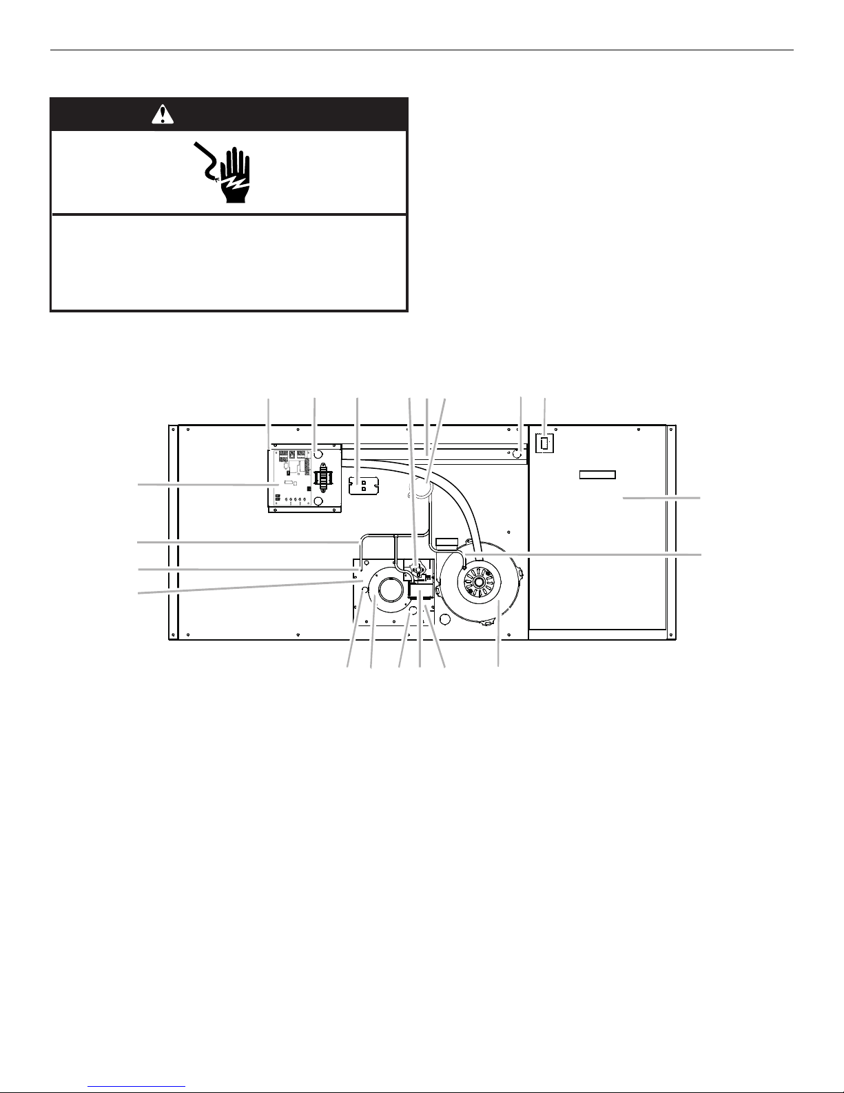
Airflow Conversion
3
4
WARNING
Electrical Shock Hazard
Disconnect power before servicing.
Replace all parts and panels before operating.
Failure to do so can result in death or electrical shock.
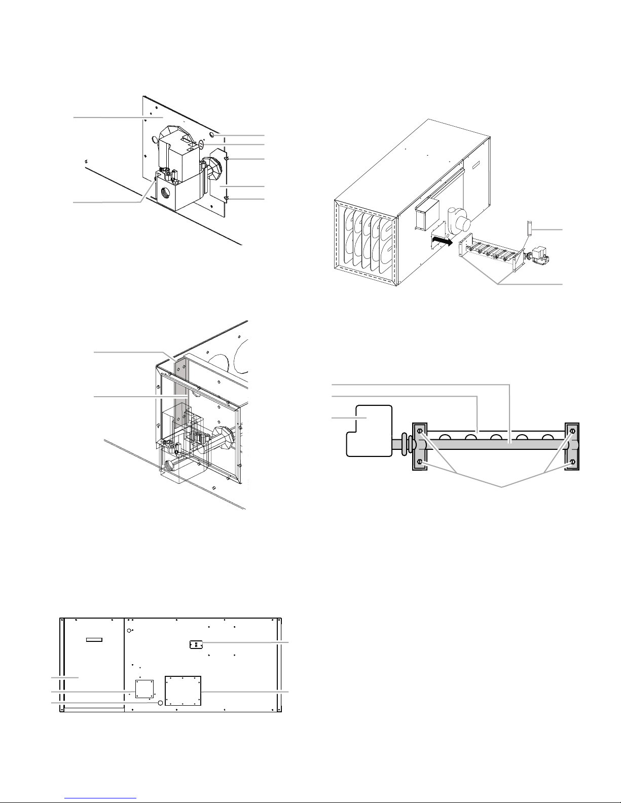
Before Conversion (original component side)
567 9108
This furnace is factory assembled for right to left airflow. It can be
converted to left to right airflow. The conversion should be made
prior to installing the unit.
IMPORTANT:
■ The sides are identified as the original component side and
the new component side. Steps 1 through 12 (following) refer
to the original component side.
■ Gas leak checking should be performed after the conversion.
See the “Make Gas Connections” section.
11 12
4
3
2
1
19
20
1. Burner access panel
2. Pressure tap
3. Pressure switch tubing
4. Blower control board
5. Control box
6. Control box bushing
7. Primary limit switch
8. Rollout switch
9. Wire channel guard
10.Pressure switch
11. Blower wire bushing
12. Blower door interlock switch
13. Circulating air blower access door
14. Combustion blower tubing
15. Combustion blower
1. Disconnect power.
2. Disconnect 3 connectors at the gas control valve and the
strain relief bushing for the cable routed through the burner
access cover.
3. Disconnect the wires from the primary limit control, pressure
switch, and rollout switch.
4. Remove the control box cover (4 screws).
5. Label wires when disconnected with the name of the terminal
on the wiring board where it is connected. Remove the
circulating air blower wires last.
1
1
15161718
16. Manifold cover
17. Gas control valve
18. Igniter wire strain relief bushing
19. PVC collar
20. Sight glass
6. Disconnect the combustion blower tubing from the
combustion blower housing.
7. Disconnect the plastic tubing from the pressure tap at the
burner access cover and the gas control valve, leaving all
remaining tubing connected to the pressure switch.
8. Remove the control box and combustion blower, leaving the
safety circuit/combustion blower circuit wiring attached to
the control box (4 screws).
9. Remove the wire channel guard (6 screws). Remove the wire
hanger P-clip located on the lower, center screw.
10. Remove the pressure switch.
11. Remove the primary limit switch.
5
12. Remove the manifold cover (2 screws), and burner access
5
4
3
2
4
4
5
cover (6 screws). Do not remove the screws located in the 2
clearance holes. The rubber grommet remains on the burner
tube.
1
2
15. Remove the 2 screws securing the burner locking tab behind
the burner access cover.
NOTE: The flange is located toward the inside.
16. On the original component side of the furnace, remove the
burner assembly (gas valve and burner piping) by lifting the
assembly from the engagement screws and then pull the
assembly straight out of the burner box.
1
1. Burner access plate
2. Clearance holes
3. Rollout switch
4. Manifold plate screws
5. Manifold plate
13. Remove the burner locking tab (2 screws).
NOTE: The flange is located toward the inside.
1
2
1. Burner locking tab
2. Locking tab flange
14. On the new component side of the furnace, remove the
following: rear blower compartment panel, rear burner access
cover (do not remove the 2 screws located in the clearance
holes), flue cover, the limit control access opening cover, the
plug closing the opening for the blower wires, and plastic
condensate drain plug (using a ¹⁄₂ in. hex-head wrench).
1
2
3
1. Rear blower compartment panel
2. Flue cover
3. Condensate drain plug
4. Limit control access cover
5. Rear blower access cover
2
1. Burner locking tab
2. Manifold support brackets
17. Remove the 4 screws holding the manifold to the burner
assembly. (If the furnace will be converted to L.P. gas, the
orifice conversion should be performed at this point). See
“Accessories” section for Propane Conversion Kit
information.
1
2
3
4
1. Manifold
2. Burner
3. Gas control valve
4. Screws
18. Hold the gas control valve with an adjustable wrench. Use a
pipe wrench to tighten the manifold clockwise ¹⁄₂ revolution
(180°), so the vertical axis of the gas control valve is
perpendicular (90°) to the burner orifices.
19. Flip the manifold so the gas valve is located on the opposite
end. Then install the manifold and gas valve to the burner
assembly, using the 4 screws removed earlier, making sure
the burner orifices seat in the burners.
20. Connect igniter wires and flame sense wire, then slide the
burner assembly into the burner box on the opposite side of
the furnace, making sure that the assembly engages onto the
alignment screws.
NOTE: Ensure the wires are not damaged during assembly or
pinched after assembly.
6
21. Install both locking tabs, using 2 screws, flange side toward
3
4
3
the burners with the flange facing out toward the blower end
of the furnace.
22. Remove the PVC collar, rollout switch, sight glass (carefully),
and pressure tap from the burner access cover.
1
2
5
6
1. Rollout switch
2. Gas control valve
3. Pressure tap
4. Burner access panel
5. Sight glass
6. PVC collar
23. Install the PVC cover, rollout switch, sight glass (carefully),
and pressure tap on the reverse side of the burner access
cover.
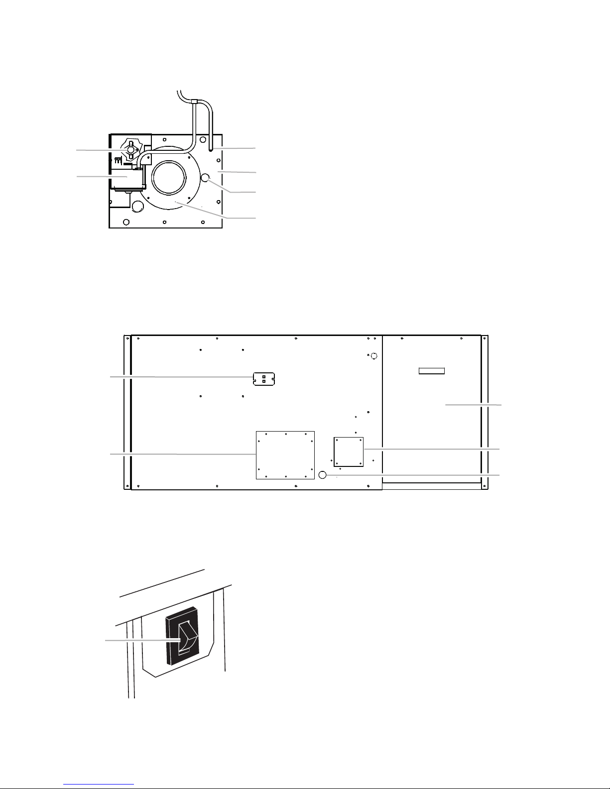
After Conversion (original component side)
24. Install the burner access cover (6 screws) and manifold cover
(2 screws), making sure the covers seal around the manifold
grommet.
NOTE: Ensure the wires are not damaged during assembly or
pinched after assembly.
25. On the original component side of the furnace, remove the
blower access door (2 screws). This door contains most
labels.
26. On the same side, feed the blower wires through the bushing
into the blower compartment and remove the bushing.
27. Install the bushing in the blower wires access opening in the
new component side.
28. Remove the blower door interlock switch (leaving the wires
connected to the switch).
29. Cut the wire tie around the blower wiring and route the wires
across the top of the blower housing to the opposite side of
the furnace, making sure all wiring is clear of the blower
intakes.
30. Install the following parts previously removed from the new
component side on the original component side: rear blower
compartment panel, rear burner access cover, flue cover, limit
control access cover, and condensate drain plug.
1
2
1. Limit control access cover
2. Rear blower access cover
3. Rear blower compartment panel
31. On the new component side of the furnace, install the blower
door interlock switch (2 screws). Ensure that the switch
actuator faces out of the blower compartment.
1
4
5
4. Flue cover
5. Condensate drain plug
1. Blower door interlock switch
32. Feed the blower and interlock switch wiring through the hole
in the blower compartment.
7
4
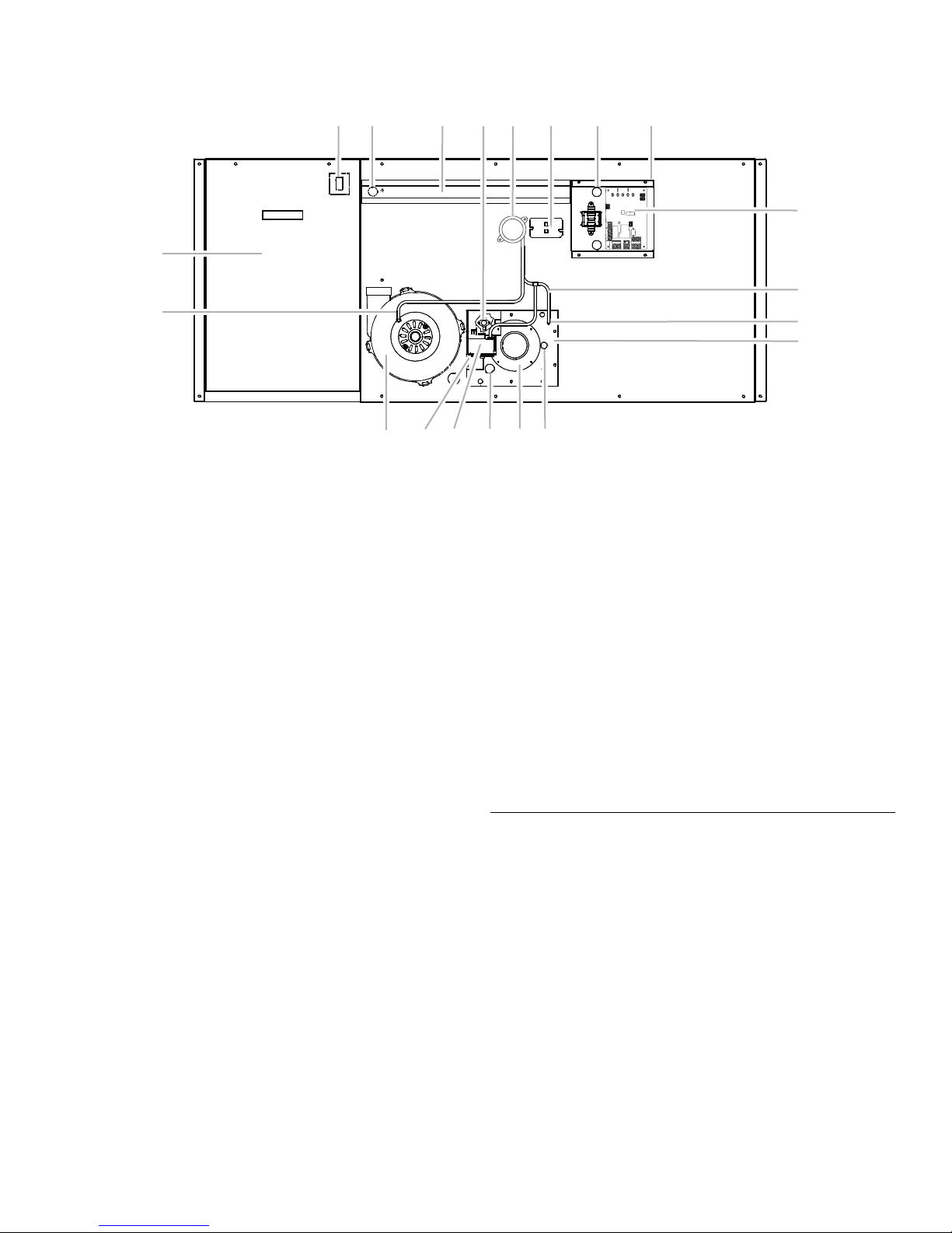
After Conversion (new component side)
12 11 8 10 7 6 5
9
13
14
1. Burner access panel
2. Pressure tap
3. Pressure switch tubing
4. Blower control board
5. Control box
6. Control box bushing
7. Primary limit switch
8. Rollout switch
9. Wire channel guard
10.Pressure switch
11. Blower wire bushing
12. Blower door interlock switch
13. Circulating air blower access door
14. Combustion blower tubing
15. Combustion blower
33. Feed all blower and interlock switch wires through the
bushing on the back side of the control box, then install the
control box.
34. Using 4 screws, install the combustion blower, making sure
the plastic combustion blower orifice seats tightly into the
flue opening.
35. Connect the circulating air blower wires to the blower control
board. Using the labels previously placed on the wires to
connect the wires to the correct terminal. A wiring diagram is
provided on the control box cover.
36. Draw wires into the blower compartment and secure with a
wire tie to avoid contact with the fan blade.
37. Route the blower wires through the wire channel guard and
install the guard making sure not to pinch any wiring between
the guard and the side panel. (Do not install the bottom
middle screw, reserve this for the P clamp.)
38. Invert the P clamp on the cable and route the combustion
blower wire conduit through the P clamp.
39. Install the blower door panel (the panel with the most labels)
on the new component side.
40. On the new component side install the limit control. Ensure
that the metal disk of the thermostat points toward the heat
exchanger end of the furnace.
3
2
1
20
1918171615
16. Manifold cover
17. Gas control valve
18. Igniter wire strain relief bushing
19. PVC collar
20. Sight glass
41. Install the pressure switch (2 screws). The pressure taps (with
tubing still installed) points toward the burner box.
42. Attach the tubing to the pressure tap on the burner access
cover and the gas valve.
43. Install the tubing to the combustion blower.
44. Connect all wire harnesses to the following components: gas
valve plugs, primary limit control terminals, pressure switch
terminals, and rollout switch terminals.
45. Install the control box to the furnace (4 screws). Ensure all
wires are routed through openings and are not pinched or
abraded. Install the control box cover.
46. Check your work to ensure that all parts are installed and
connected. Clean up all debris.
47. Complete propane conversion if the orifice conversion was
performed in step 17.
Duct Work Requirements
Install the conditioned air plenum, ducts and air filters (not
provided) in accordance with NFPA 90B Standard for the
Installation of Warm Air Heating and Air-Conditioning Systems
(latest edition).
The furnace is provided with flanges for the connection of the
plenum and ducts.
Air Filters must be listed as Class 2 furnace air filters.
8
 Loading...