

Whirlpool WFC7500VW1 Parts Diagram
FOR SERVICE
T
A
r
c
u
A
a
r
TECHNICIAN
ONLY
- DO NOT
REMOVE OR
DESTRO
Electrostatic Discharge (ESD)
ESD problems are
weaken the
assembly may appear to work
failure may occur at a later date due to ESD stress.
Use
ground connection point or unpainted
appliance
T
ouch your finger repeatedly to a green ground
point or unpainted
Before removing
anti-static bag to a green ground connection point or
unpainted
A
void touching electronic parts or
handle electronic control assembly by edges only.
When repackaging
anti-static bag,
electronic control assembly.
an
anti-static
metal in the
IMPOR
NT
Sensitive Electronics
present
everywhere. ESD may damage or
well
after
wrist strap.
metal in the
the
Connect
-OR-
appliance.
part from
appliance.
its
terminal
failed
observe above
electronic control assembly in
instructions.
The
new c
ontrol
repair is finished,
wrist strap to green
metal in the
connection
package, t
ouch
contacts;
DIAGNOSTIC GUIDE
Before
servicing,
Make sure there is power at
Has a household fuse blown or circuit
delay fuse?
Are both hot and cold water
unobstructed?
All tests/checks should be made with a VOM or DVM having a
sensitivity of 20,000 ohms per
Check all connections before replacing components. Look
broken or loose wires,
connections
A potential
connections.
ohmmeter.
Connectors: Look at top of connector.
wires. Check
engage
Resistance checks must be made with power cord unplugged
outlet, and with wiring harness or connectors disconnected.
check
far enough.
cause of a
Observe connections and check
for
metal
wires not pressed into connector far enough to
barbs.
the
following:
failed terminals, or
control not functioning is corrosion on
the wall
outlet.
breaker
faucets
open and water supply
volt DC or greater.
wires not pressed into
Check
tripped? T
for
continuity with
for
broken or loose
the
ime
for
Y
but
hoses
an
from
POURLETECHNICIEN
Circuits é lectroniques sensibles
aux dé
Le
risque de dé
décharge é
composants é
l’impression
charge é
lectrostatique peut endommager ou
lectroniques. La nouvelle
qu’elle fonctionne correctement après la
réparation, mais une décharge é
fait subir des
plus tard.
Utiliser un bracelet de décharge é
le
bracelet à la vis verte de
dommages
métallique non peinte de
T
oucher
plusieurs fois du
ou
terre
une surface métallique non peinte de
A
vant de retirer la pièce de
antistatique en contact avec la vis verte de
une surface métallique non peinte de
É viter de toucher les composants é
broches de contact; tenir la
par les bords seulement
Lors du ré
défaillante dans
instructions
GUIDE
vant d
’entreprendre
Vérifier que la prise de
F
usible grillé ou
Robinets d
d’eau exempts d
Utiliser pour tous les contrô
dont la résistance
ou plus.
Contrô ler
Rechercher
cosses
Le
non-fonctionnement d’un
corrosion des pièces de
ler la
Connecteurs :
des fils brisés ou
mal branchées.
Lors de
d’alimentation
faisceaude câ
emballage
le sachet
ci-dessus.
DE
DIAGNOSTIC
une réparation, contrô ler ce
disjoncteur ouvert? Fusible
’eau chaude et d
’obstruction?
de connexion dété
continuité
toute mesure de résistance, vérifier que
interne est de 20 000
toutes les
des
fils brisés ou mal connectés, ou des bornes ou
avec un
Examiner
mal connectés; rechercher également des cosses
est débranché de la
blage ou
SEULEMENT- NEP
IMPORT
charges é
lectrostatique
AS ENLEVERNIDÉTRUIRE
ANT
lectrostatiques
est permanent. Une
carte peut
lectrostatique peut
qui
provoqueront
lectrostatique. Connecte
liaison à la
l’appareil
-OU-
terre ou sur une surfa
doigt la vis verte de
son sachet,
placer
l’appareil.
lectroniques ou les
lors
d’une
carte de
carte de
circuits é
des manipulations.
circuits é
antistatique, appliquer les
courant
connexions
est alimentée.
’eau froide ouverts et tuyaux d
les un voltmètre ou autre instrument
avant de remplacer un composant.
riorées.
organe de
connexion. Inspecter
ohmmètre.
le
sommet d
le
connecteur est débranché.
prise de
temporisé
ohms
commande
les
’un connecteur; rechercher
courant, et
affaiblir les
donner
lui avoir
une défaillance
liaison à
l’appareil.
le sachet
liaison à la
terre
lectroniques
lectroniques
qui suit :
par volt CC
grillé?
peut être dû à
connexions
le
cordon
que
’arrivée
le
la
et
o
l
cont
PART
NO.
46197042905
PAGE
1
Date : 14-Feb-2008
FOR SERVICE
TECHNICIAN
ONLY
- DO NOT
REMOVE OR
DESTRO
Y
POURLETECHNICIEN
SEULEMENT- NEP
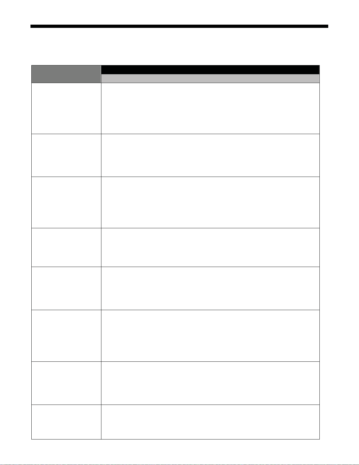
TROUBLESHOOTING GUIDE
NOTE: After problem(s) are fixed, please run the diagnostic test to ensure that there have no other issues.
POSSIBLE CAUSE/TEST PROBLEM
NOTE: Possible Cause/Tests must be performed in the sequence shown for each problem.
WON'T POWER UP
(buttons do not respond when
pressed)
WON'T START CYCLE
WON’T SHUT OFF
CONTROL WON'T ACCEPT
SELECTIONS
1. Check that the unit is plugged into a working outlet and for blown fuses.
2. Check for power going to Central Control Unit (CCU) by listening for a click in the CCU when unit is plugged in. If no
click, replace CCU.
3. Unplug washer or disconnect power.
4. Check continuity of line cord and line filter.
5. Check harness connections to CCU.
6. Plug in washer or reconnect power.
7. Check the button/LED assembly by selecting different cycles and changing the modifiers and options available to
confirm the button/LED assembly is responding.
8. Check the connection of the power cord to the line filter and at the CCU. Check to confirm the door closes fully.
1. Open and close the door. The door has to be opened between consecutive wash cycles.
2. Check the door switch/lock unit using the diagnostics. See Quick Diagnostic Test.
3. If door is locked, drain the unit.
4. Unplug washer or disconnect power.
5. Check the wire harness connections.
6. Plug in washer or reconnect power.
7. Check the button/LED assembly by selecting different cycles and changing the modifiers and options available to
confirm the button/LED assembly is responding.
1. Check for a Fault/Error Code on the display.
2. Switch knob to OFF position.
3. Check the button/LED assembly by selecting different cycles and changing the modifiers and options available to
confirm the button/LED assembly is responding.
4. Unplug washer or disconnect power.
5. Check that the drain hose and drain pump filter are clear of foreign objects and not plugged.
6. Plug in washer or reconnect power.
7. Check drain pump.
8. Verify CCU operation by running a Quick Diagnostic Test or any cycle.
9. Check Knob assembly on the CCU to ensure the direction is properly oriented. See page 9.
1. Switch knob to OFF position.
2. Drain the unit, and then check that the drain hose and drain pump filter are clear of foreign objects.
3. Check the button/LED assembly by using the Universal test mode.
4. Unplug washer or disconnect power.
5. Check harness connections.
6. Plug in washer or reconnect power.
7. Verify CCU operation by running a Diagnostic Test or any cycle.
AS ENLEVERNIDÉTRUIRE
WON'T DISPENSE
WON'T FILL
OVER FILLS
DRUM WON'T ROTATE
1. Verify the unit is level.
2. Verify dispenser drawer is not clogged with detergent.
3. Check water connections to the unit and within the unit. Check for plugged screen in water source.
4. Check the water supply and the water valve.
5. Unplug washer or disconnect power.
6. Check harness connections.
7. Plug in washer or reconnect power.
8. Verify CCU operation by running a Quick Diagnostic Test or any cycle.
1. Check installation. Verify hot and cold water faucets are open.
2. Check inlet valves.
3. Unplug washer or disconnect power.
4. Check water connections to the unit and within the unit. Make sure water supply hoses are unobstructed. Check for
plugged screen.
5. Plug in washer or reconnect power.
6. Check operating pressure switch.
7. Check drain pump motor.
8. Verify CCU operation by running a Quick Diagnostic Test or any cycle.
9. Check the steps listed under WON'T DISPENSE.
1. Verify the unit is level.
2. Check pump drain system – this could indicate a failure to drain.
3. Unplug washer or disconnect power.
4. Check operating pressure switch.
5. Check pressure switch hose.
6. Plug in washer or reconnect power.
7. Verify flow meter operation by blowing air though the part and measuring the resistance.
8. Verify CCU operation by running a Quick Diagnostic Test or any cycle.
1. Check drive belt.
2. Check drive motor.
3. Unplug washer or disconnect power.
4. Check wire harness connections.
5. Plug in washer or reconnect power.
6. Perform the Motor Continuity Test.
PART
NO.
46197042905
PAGE
2
Date : 14-Feb-2008
FOR SERVICE
TECHNICIAN
ONLY
- DO NOT
REMOVE OR
DESTRO
Y
POURLETECHNICIEN
SEULEMENT- NEP
AS ENLEVERNIDÉTRUIRE
MOTOR OVERHEATS
WON'T DRAIN
MACHINE VIBRATES
INCORRECT WATER
TEMPERATURE
DISPLAY FL ASHING
1. Check drive motor.
2. Unplug washer or disconnect power.
3. Check wire harness connections.
4. Check drive belt.
5. Plug in washer or reconnect power.
6. Check for obstruction between the spin basket and the outer tub.
1. Unplug washer or disconnect power.
2. Check wire harness connections.
3. Check drain pump.
4. Check drain pump motor.
5. Check that the drain hose and drain pump filter are clear of foreign objects.
6. Plug in washer or reconnect power.
7. Verify CCU operation by running a Quick Diagnostic Test or any cycle.
1. Remove shipping system.
2. Check installation.
3. Check leveling feet.
1. Check that the inlet hoses are connected properly.
2. Unplug washer or disconnect power.
3. Check water temperature sensor for an abnormal condition. See the Water Temperature Sensor section, page 10.
4. Plug in washer or reconnect power.
5. Verify CCU operation by running a Diagnostic Test or any cycle.
See Failure/Error Display Codes.
DIAGNOSTIC TEST
The two test modes contain three modes of operation.
Test modes:
Universal test mode, with additional user interface test at the beginning
Quick test mode
Operation modes:
User interface test
Automated test
Loads tests to assist in diagnosing potentially non-electrical issue
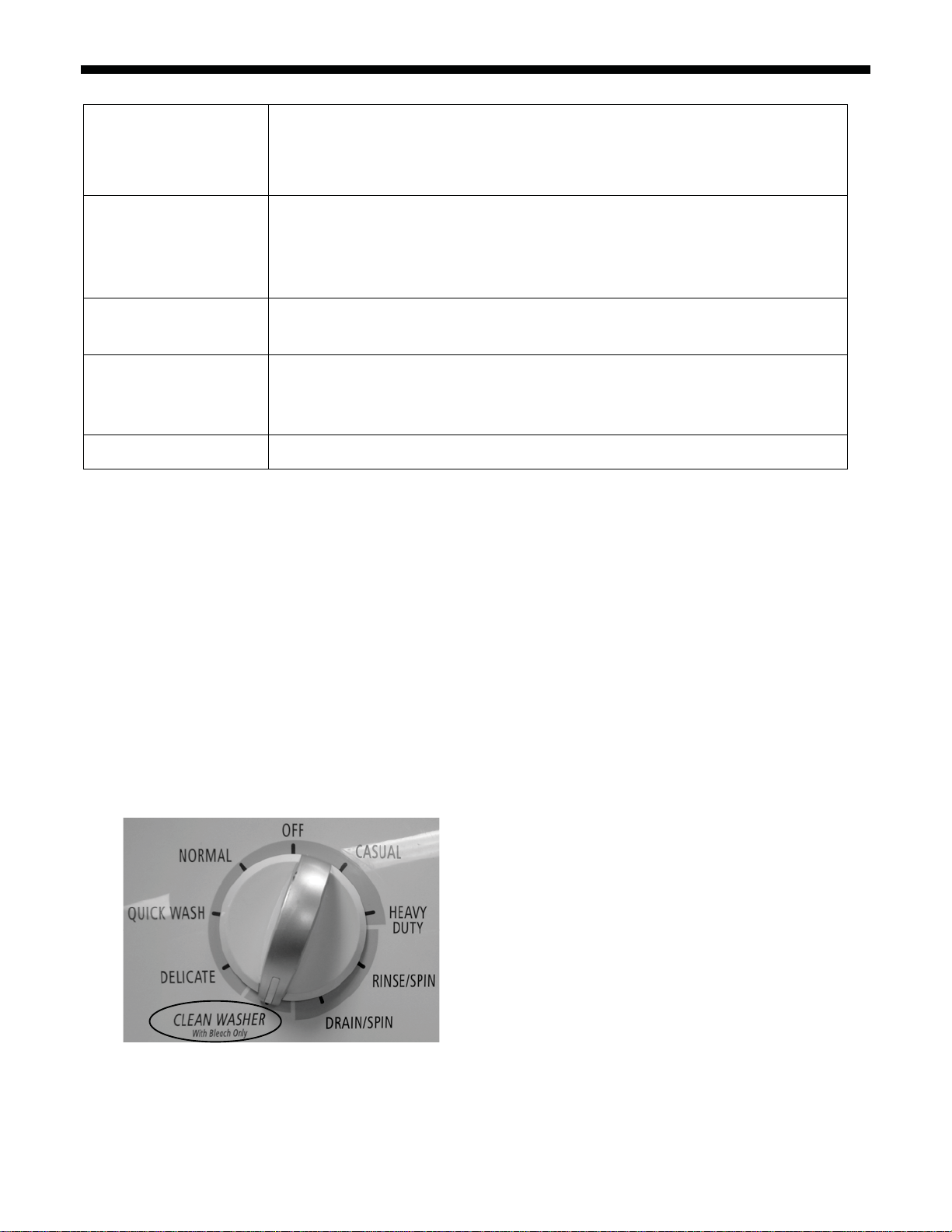
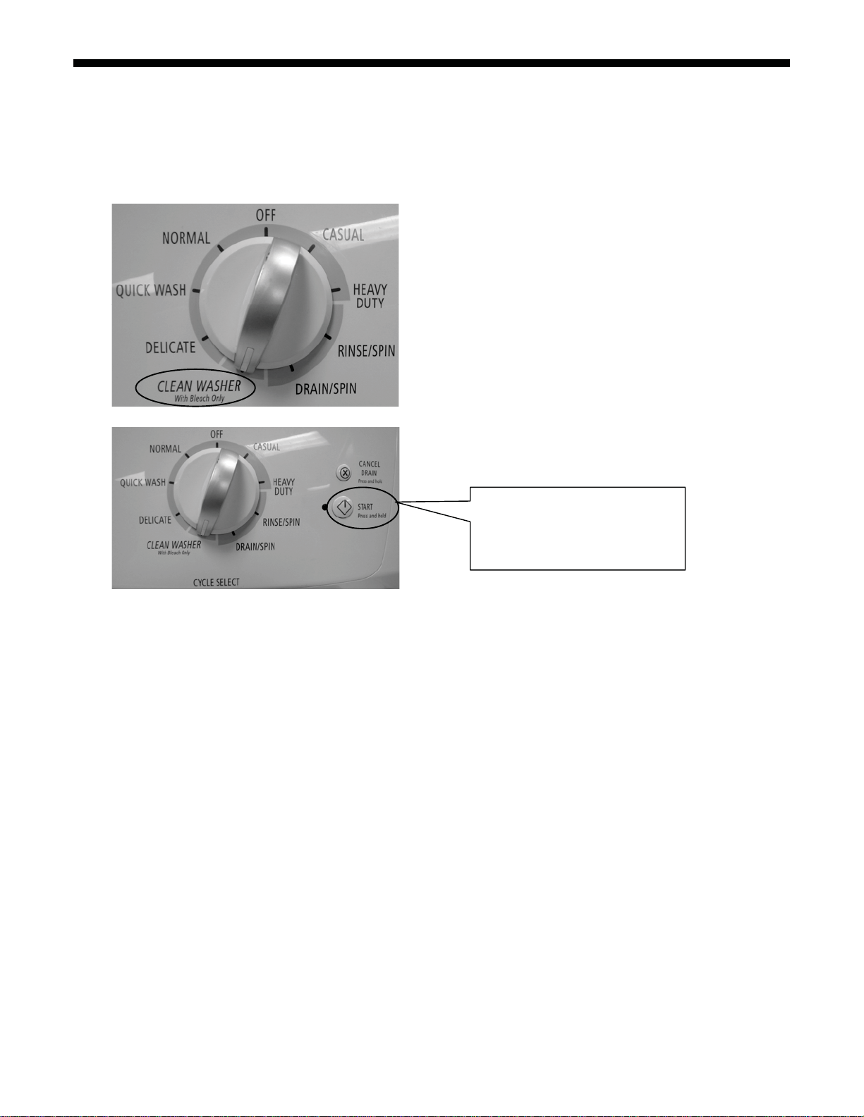
Startin g Univ ers al Test Mode
1. Close the door
2. Rotate the knob and select the CLEAN WASHER cycle. (See picture below)
PART
NO.
46197042905
PAGE
3
Date : 14-Feb-2008
FOR SERVICE
TECHNICIAN
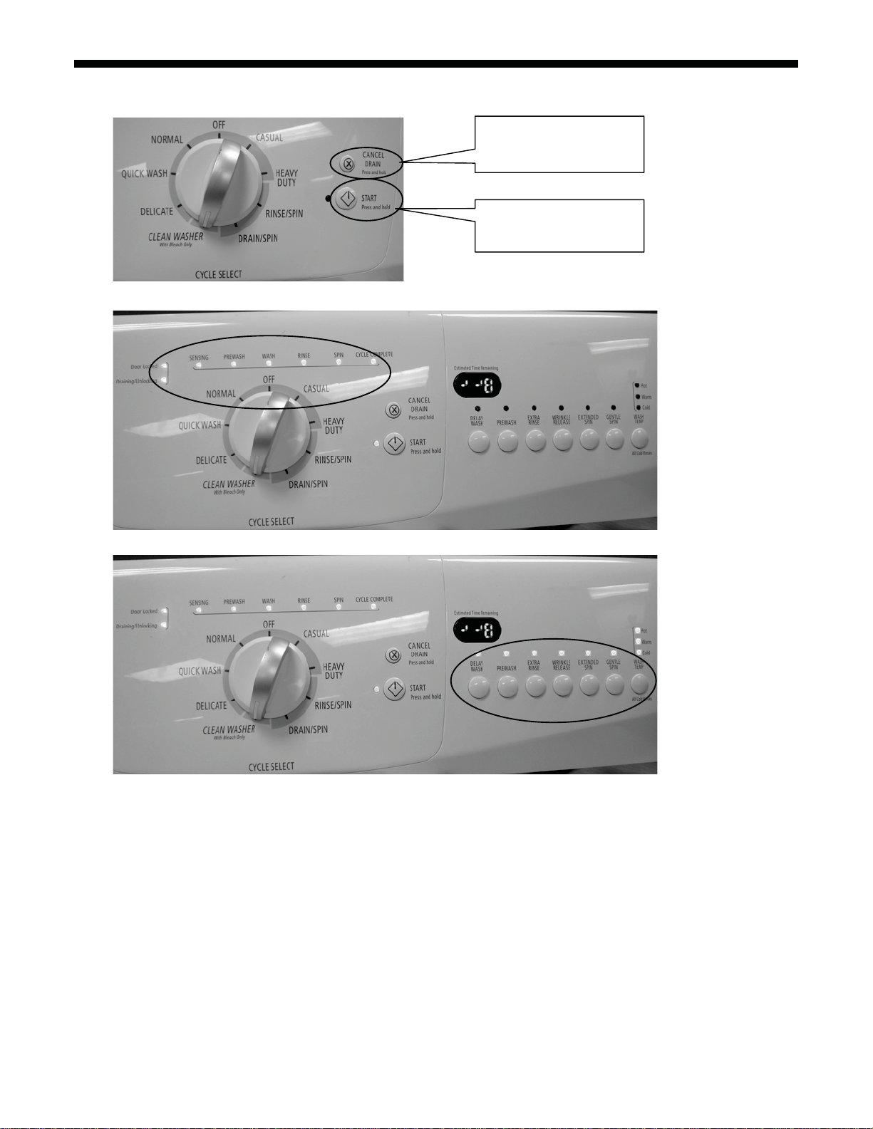
3. Press “CANCEL/DRAIN” button for 2 times, and then press “START” button for 2 times within 5 seconds. (See pictures below)
4. Upon release, and after door locked, all console LED lights will turn ON except option LED. (See pictures below)
5. Press the option buttons, one at a time, to check the User Interface
6. Following steps are automatically driven, or they can be manually advanced by pressing the Cancel/Drain button 2 time. See table
UNIVERSAL DIAGNOSTICS TEST” on next page.
“
ONLY
- DO NOT
REMOVE OR
DESTRO
Y
POURLETECHNICIEN
First press “CANCEL/DRAIN”
button for 2 times
Then press “START” button for
2 times within 5 seconds.
SEULEMENT- NEP
AS ENLEVERNIDÉTRUIRE
NOTES:
To cancel out of this mode rotate the selector knob. (This exits you out of the program.)
Press “CANCEL/DRAIN” button 2 times can advance to the next step of the procedure.
If the starting procedure fails, switch the knob and back to the CLEAN WASH cycle, the repeat the starting procedure.
PART
NO.
46197042905
PAGE
4
Date : 14-Feb-2008
FOR SERVICE
TECHNICIAN
ONLY
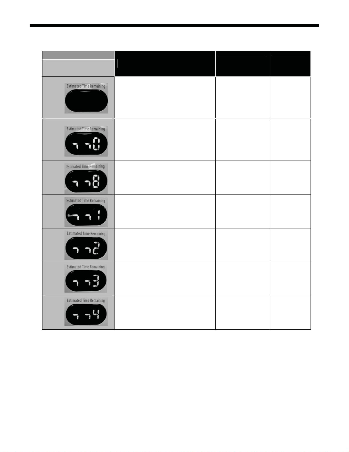
UNIVERSAL DIAGNOSTICS TEST
- DO NOT
REMOVE OR
DESTRO
Y
POURLETECHNICIEN
SEULEMENT- NEP
AS ENLEVERNIDÉTRUIRE
Indication
Factory Test Display
(7-SEGMENT LED)
OFF
0 (Phase LED rolling)
8
1
2
3
4
Control Action
Door locks Door lock system F13
Checks the EEPROM data’s validity
Pump turns ON if the water level is detected to be
above the wash level
All display led are turned on
UI option led will be turned on after options are
pushed.
Turns hot valve inlet on (About 15s)
Turns bleach valve inlet on (About 15s)
Turns cold valve inlet on (About 15s)
Fill by cold water inlet valve to Level_wash
Motor reverse. Runs at normal washing speed.
(About 15s)
Pump turns ON to drain the washer Drain system F03, F21
Drive motor to max speed Motor speed
Actuators to be
Checked
Drain system
EEPROM test
User interface F21, F25
Hot Water inlet valve
Cold Water inlet valve
Bleach inlet valve
Reversing relay
Safety relay
Motor thermistor
Tachometer signal
Tap field relay
Failure code
for failure mode
F03, F05, F14,
F21, F23, F24,
F26, F30
F01, F21, F23,
F24
F06, F07, F21,
F27
F06, F07, F21,
F27, F28
PART
NO.
46197042905
PAGE
5
Date : 14-Feb-2008
FOR SERVICE
TECHNICIAN
ONLY
- DO NOT
REMOVE OR
DESTRO
Y
POURLETECHNICIEN
SEULEMENT- NEP
AS ENLEVERNIDÉTRUIRE
Starting Quick Test Mode
All of the steps below must be done in sequence in order to reach the Diagnostic Test. This executes the automatic test but does not run
the user interface test
1. Close the door
2. Switch the knob and select the CLEAN WASHER cycle. (See picture below)
3. Press “START” button for 4 times within 5 seconds. (See picture below)
NOTES:
Please ensure that current machine status is in PROGRAM (SELECTION) mode.
Otherwise, please follow the instructions below to bring it back to PROGRAM
(SELECTION) mode.
1) PAUSE mode: Press and hold CANCEL/DRAIN button for 3 seconds for
reset, then switch knob to enter PROGRAM mode
2) FAILURE mode: Switch knob to enter PROGRAM mode
3) EXECUTION mode: Press and hold CANCEL/DRAIN button for 3 seconds
for reset, then switch knob to enter PROGRAM mode
4) STANDBY mode: Press START button or switch knob to enter PROGRAM
mode
5) DELAY START mode: Switch knob to enter PROGRAM mode
First press “START” button for 4 times
within 5 seconds
4. Following steps are automatically driven, or they can be manually advanced by pressing the Cancel/Drain button 2 times. See table
“
QUICK DIAGNOSTICS TEST” on next page.
NOTES:
To cancel out of this mode rotate the selector knob. (This exits you out of the program.)
Press “CANCEL/DRAIN” button 2 times can advance to the next step of the procedure.
If the starting procedure fails, switch the knob and back to the CLEAN WASH cycle, the repeat the starting procedure.
PART
NO.
46197042905
PAGE
6
Date : 14-Feb-2008
 Loading...