

Whirlpool WFC310S0EB Service and Maintenance Guide
W11327942A
NOTE: This sheet contains important Technical Service Data.
FOR SERVICE TECHNICIAN ONLY
DO NOT REMOVE OR DESTROY
FOR SERVICE TECHNICIAN’S USE ONLY
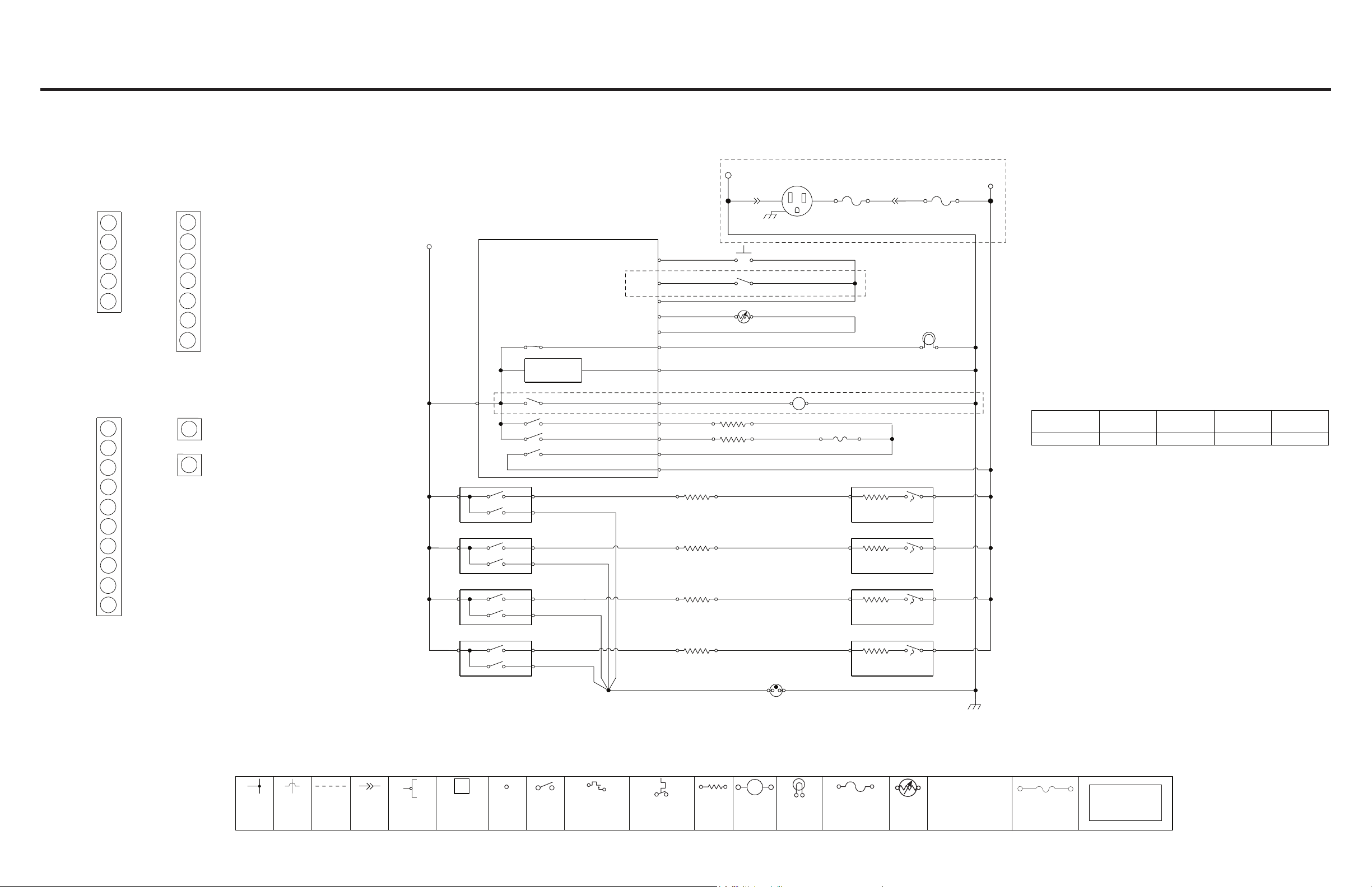
Wiring Diagram
Quick Connect Plugs Oven Control Wiring Diagram
For oven controls
NOTE: Schematic shows door latch switch in the COOK position with oven door open and elements off.
Do Not Remove Or Destroy
CON1
1
W
BR
BK
CON3
1
BU
Y
GY
CON2
1
BU
BK
R
CON4
1
R
1
R
L1
BK
BK
BK
CON2-4
L1
Oven Control LCC
Oven Light (K2)
Power Supply
Latch Motor (K1)
Bake (K4)
Broil (K3)
DLB (K5)
H1
OR
P
LF
V
N
Outlet
15 Amp Non-resettable Fuse
(Alternate Construction)
W
W
GND
W
CON3-3
CON3-1
CON3-4
CON3-9
CON3-10
CON1-5 W
CON1-1
CON1-4
CON2-7
CON2-1
CON4
CON4
Y
BU
GY
V
V
BK
W
BR
R
BU
Bake 2400 W
Broil 3400 W
R
R
Left Front Element
Door Position Switch
Y
Door Latch Switch
BU
Oven Temp Sensor
M
BU/W
Opens @ 363˚F (184˚C)
Latch Motor 4 W
R
Thermo Fuse
H2
OR
R
15 Amp Resettable Fuse
R
RR
Oven Light Assy 40 W
LF
L2
L2
R
W
R
W
W
R
R
Coil Cooktop
Configuration
Left Front
Element
Left Rear
Element
Right Rear
Element
1 2400 W 1500 W 2400 W 1500 W
Right Front
Element
W11327942A
L1
BK
V
V
L1
BK
BK
Infinite Switches
(cycle On/Off when hot)
LR
RR
RF
H1
P
V
H1
P
V
1H1L
P
V
Y
BU
BR
Left Rear Element
Right Rear Element
Right Front Element
V
Cooktop ON
Indicator Light
(On when any element
is turned On)
Y
BU
BR
H2
H2
H2
W
L2
R
LR
L2
R
RR
L2
R
RF
GND
LEGEND
Connection
No
Connection
On Some
Models
In Line
Connection
Component
Terminals
Circuit r y
Enclosed Within
Terminals
Single
Switch
Thermal Switch
(opens on heat rise)
Thermal Switch
(closes on heat rise)
Resistor or
Element
©2019 All rights reserved.
M
Motor
Incandescent
Light
Non-resettable Fuse
Thermistor
CON1-2 = Connector 1
CON1 Position 2
Thermo Fuse
Multiple
Functions / Circuitry
Enclosed Within
06/19
 Loading...