

Whirlpool W11114976B Service Data Sheet
FOR SERVICE TECHNICIAN’S USE ONLY
Voltage Measurement Safety Information
When performing live voltage measurements, you must do the following:
Verify the controls are in the off position so that the appliance does not start when energized.
Allow enough space to perform the voltage measurements without obstructions.
Keep other people a safe distance away from the appliance to prevent potential injury.
Always use the proper testing equipment.
After voltage measurements, always disconnect power before servicing.
IMPORTANT: Electrostatic Discharge (ESD) Sensitive Electronics
ESD problems are present everywhere. Most people begin to feel an ESD discharge at
approximately 3000V. It takes as little as 10V to destroy, damage, or weaken the main control
assembly. The new main control assembly may appear to work well after repair is finished,
but a malfunction may occur at a later date due to ESD stress.
Use an anti-static wrist strap. Connect wrist strap to green ground connection point or
unpainted metal in the appliance
-OR Touch your finger repeatedly to a green ground connection point or unpainted metal
in the appliance.
Before removing the part from its package, touch the anti-static bag to a green ground
connection point or unpainted metal in the appliance.
Avoid touching electronic parts or terminal contacts; handle electronic control assembly
by edges only.
When repackaging main control assembly in anti-static bag, observe above instructions.
This service data sheet is intended for use by persons having electrical, electronic, and
mechanical experience and knowledge at a level generally considered acceptable in the
appliance repair trade. Any attempt to repair a major appliance may result in personal injury
and property damage. The manufacturer or seller cannot be responsible, nor assume any
liability for injury or damage of any kind arising from the use of this data sheet.
Contents
IMPORTANT SAFETY NOTICE — “For Technicians only”
Control Panels .........................................2–5
Diagnostic Guide .........................................6
Fault/ Error Codes (Washer).........................7
Washer Troubleshooting Guide ................8, 9
Manual Test Mode (Washer) ......................10
PART NO. W11114976B
User Interface/Control Board (Washer) ......11
Rear View of Washer .................................12
Dryer Troubleshooting Guide .....................13
Dryer Troubleshooting Tests ................14–17
Wiring Diagrams .................................18–20
PAGE 1
FOR SERVICE TECHNICIAN’S USE ONLY
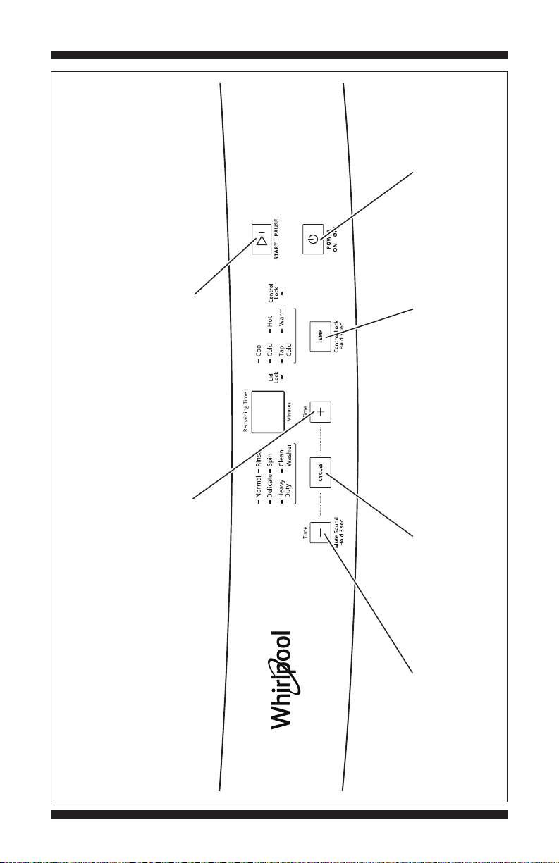
button exits the
Pressing the Power
UI/LED Test Mode.
the indicator.
Pressing the Start/Pause
test. Press once to turn off
button begins or continues the
Pressing the “+” button
turns on/off the 7-segment display.
Pressing the
Pressing the
Pressing the “–” button
temperature
Temp button
corresponding
turns on/off each
Cycles button
corresponding
cycle indicator.
turns on/off each
and lid lock indicators.
turns on/off the control lock
indicator.
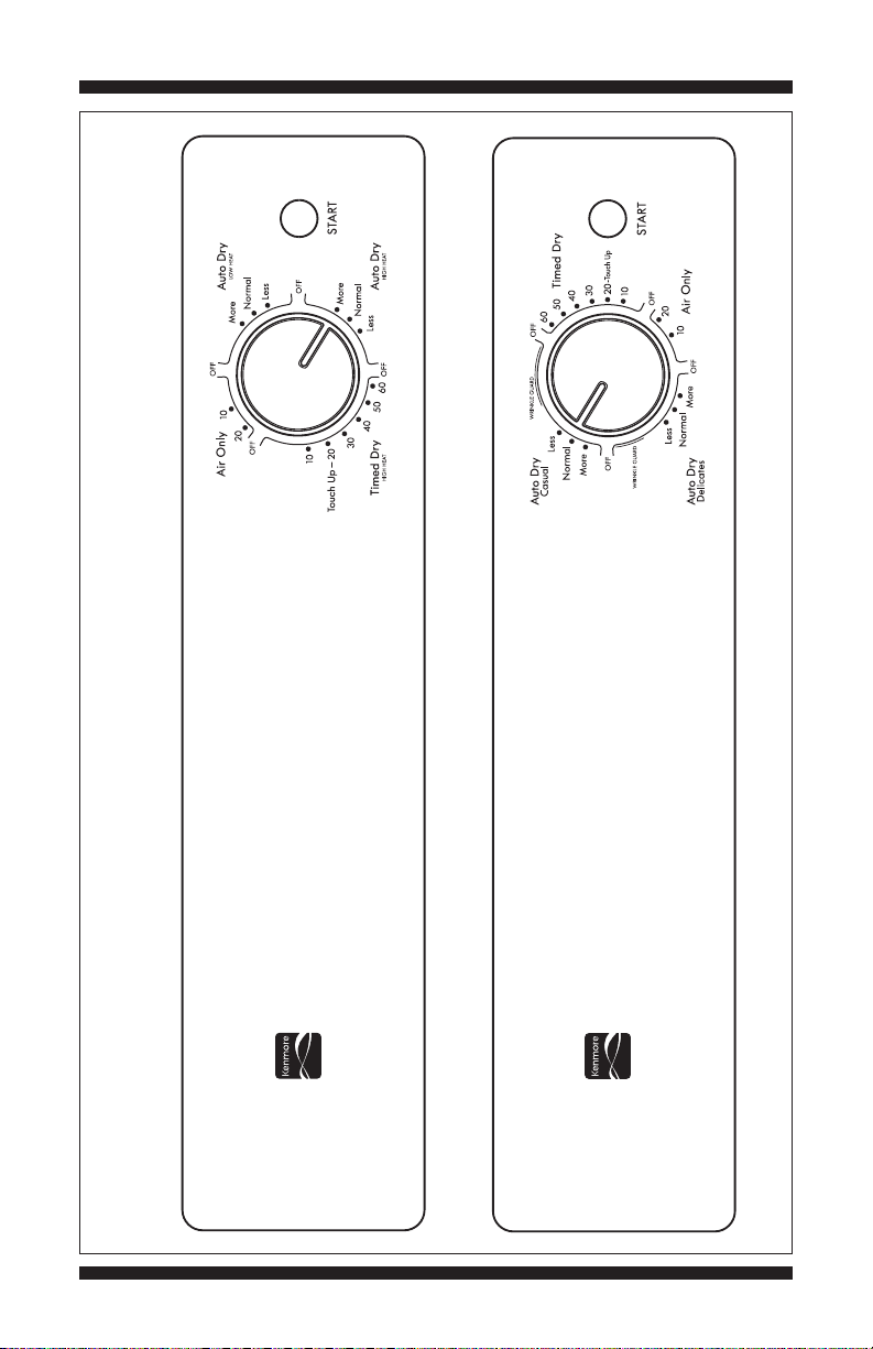
WHIRLPOOL WASHER CONTROL PANEL
PAGE 2
Figure 1a - User Interface Test, Whirlpool Washer
DO NOT REMOVE OR DESTROY
FOR SERVICE TECHNICIAN’S USE ONLY
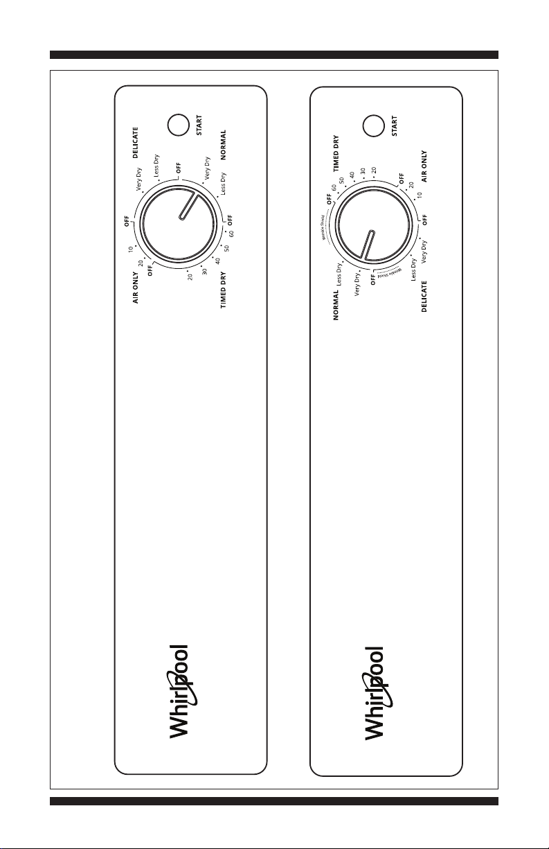
240V MODEL
WHIRLPOOL DRYER CONTROL PANEL (appearance may vary)
DO NOT REMOVE OR DESTROY
120V MODEL
Figure 1b - User Interface Test, Whirlpool Dryer
PAGE 3
FOR SERVICE TECHNICIAN’S USE ONLY
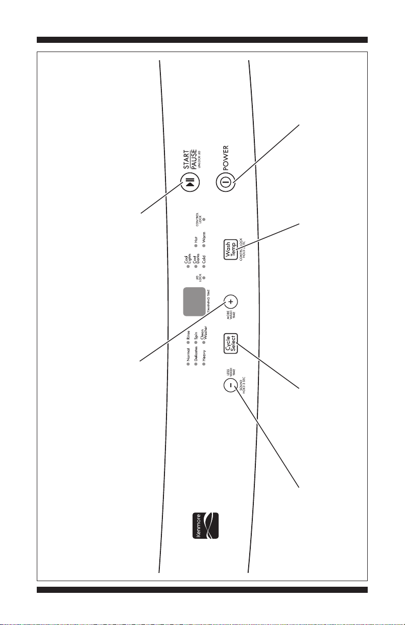
button exits the
Pressing the Power
UI/LED Test Mode.
the indicator.
Pressing the Start/Pause
test. Press once to turn off
button begins or continues the
Pressing the “+” button
turns on/off the 7-segment display.
Pressing the
Pressing the
Pressing the “–” button
temperature
corresponding
turns on/off each
Wash Temp button
corresponding
cycle indicator.
turns on/off each
Cycle Select button
and lid lock indicators.
turns on/off the control lock
indicator.
KENMORE WASHER CONTROL PANEL
PAGE 4
Figure 1c - User Interface Test, Kenmore Washer
DO NOT REMOVE OR DESTROY
FOR SERVICE TECHNICIAN’S USE ONLY
240V MODEL
KENMORE DRYER CONTROL PANEL (appearance may vary)
DO NOT REMOVE OR DESTROY
120V MODEL
Figure 1d - User Interface Test, Kenmore Dryer
PAGE 5

FOR SERVICE TECHNICIAN’S USE ONLY
DIAGNOSTIC GUIDE
Before servicing, check the following:
Make sure there is power at the wall outlet.
Has a household fuse blown, or circuit
breaker or GFCI tripped? Was a regular fuse
used? Inform customer that a time-delay fuse
is required.
Is dryer vent properly installed and clear
of lint or obstructions?
Make sure both hot and cold water faucets
are open and water supply hoses are
unobstructed.
Make sure drain hose is not sealed into
drain pipe, and that there is an air gap for
ventilation. See Installation Instructions for
other drain hose installation considerations.
All tests/checks should be made with a
VOM (volt-ohm-milliammeter) or DVM
(digital-voltmeter) having a sensitivity of
20,000 Ω per volt DC or greater.
Resistance checks must be made
with washer/dryer unplugged or power
disconnected.
IMPORTANT: Avoid using large
diameter probes when checking harness
connectors as the probes may damage
the connectors upon insertion.
Check all harnesses and connections
before replacing components. Look for
connectors not fully seated, broken or
loose wires and terminals, pin insertion,
or wires not pressed into connectors
far enough to engage metal barbs.
A potential cause of a control not
functioning is corrosion or contamination on
connections. Use an ohmmeter to check for
continuity across suspected connections.
PAGE 6
DO NOT REMOVE OR DESTROY

FOR SERVICE TECHNICIAN’S USE ONLY
FAULT/ERROR CODES (WASHER) – The fault codes below may be indicated
under various conditions.
Display Explanation and Recommended Procedure
EA Water Level Sensor
This error code will appear if the pressure sensor is damaged (outside a
specific frequency range). The washer will beep and this error code will
appear when the water level reaches approximately 3/4" (18 mm) below
the overflow point for 3 seconds. It will then pause, drain the water to the
highest load size level, then turn off the pump. The lid will remain locked.
Check connections between UI and water level sensor. Test water level
sensor in Manual Load Test, page 10.
E1 Low/No Water Fill
This error code will appear if the water level in the washer does not reach
the lowest level within 10 minutes or the set level within 20 minutes of
starting a cycle. Check water valve connections. Test water valves and
water level sensor in Manual Load Test, page 10.
E2 Abnormal Drain
This error code will appear if the washer fails to reach the reset level after
draining the water for 8 minutes. Check installation of drain hose, check
drain hose for obstructions, and check connections between UI and drain
pump. Test drain pump in Manual Load Test, page 10.
E3 Abnormal Spin
This error code will appear if the tub strikes the tub switch several times
without balancing itself. In a spin only cycle, the error code will appear the
first time the tub strikes the tub switch. See Spin Test, page 10.
EC Abnormal Circuit Motor Pulse Detection
The motor functions, but the circuit cannot detect the motor pulses.
The lid will remain locked for 5 minutes.
E4 Lid Open
This error code will appear if the washer lid is opened or if the lid switch
is open at the start of the spin during a rinse and spin cycle. Close lid.
See Lid Switch Test, page 10.
EL Lid Lock Malfunction
This error code will appear if the washer makes 10 unsuccessful attempts
to lock the lid or if the lid is detected as open during the wash or spin phase
where it must be closed and locked. Check for interference with lid or lid
lock mechanism. See Manual Load Test and Lid Switch Test, page 10.
E5 Class B Software Error
Any class B software error will display E5.
EP EEPROM Abnormal
EEPROM is corrupted.
DO NOT REMOVE OR DESTROY
PAGE 7
FOR SERVICE TECHNICIAN’S USE ONLY
WASHER TROUBLESHOOTING GUIDE NOTE: Always check for error codes first (pg. 7).
Problem Possible Cause Checks & Tests
Won’t Power Up No power to washer. Check power at outlet, check circuit breakers, fuses,
• No operation or junction box connections. If fuse or circuit breaker
• No button response blows repeatedly, washer capacitor or motor may be
• No LEDS or display defective. If so, replace it.
Connection problem between Check the AC power cord for continuity.
AC plug and UI.
User Interface/Control problem. See UI/LED Test, page 10.
Won’t Start Cycle Lid lock mechanism not 1. Lid not closed due to interference.
No response when functioning. 2. Lock not closed due to interference.
Start is pressed 3. See Lid Switch Test, page 10.
4. Check lid lock solenoid in Manual Load Test, page 10.
User Interface/Control problem. See UI/LED Test, page 10.
UI Won’t Accept User Interface/Control problem. See UI/LED Test, page 10.
Selections
Some or all buttons
non-responsive
No Sounds When Button sounds are turned off. Press “–” for 3 seconds to turn on button sounds.
Buttons Are Pressed
Won’t Fill No water supplied to washer. 1. Check water connections to washer.
2. Verify that hot and cold water supply is on.
Plugged filter/screen. Check for plugged filter or screen in the water valve
or hoses.
Water valve problem. Check water valve connections. If good, check function
of hot and cold water valves in Manual Load Test, page 10.
User Interface/Control problem. See UI/LED Test, page 10.
Overfills Pressure hose problem. Check pressure hose connections. Make sure hose is
routed correctly and not pinched. Check hose for leaks.
Replace hose if needed.
Water level sensor problem. Replace water level sensor.
Water valve problem. Check function of hot and cold water valves in Manual
Load Test, page 10.
Drain hose incorrectly installed. The top of the standpipe must be at least 39" (991 mm)
high and no higher than 72" (1.8 m) from the bottom
of the washer.
User Interface/Control problem. See UI/LED Test, page 10.
Incorrect Water Water hose installation. Make sure inlet hoses are connected properly.
Temperature
or hoses.
Water valve problem. Check water valve connections. If good, check function
of hot and cold water valves in Manual Load Test, page 10.
User Interface/Control problem. See UI/LED Test, page 10.
Won’t Agitate Lid not closed/lid lock 1. Lid not closed due to interference.
mechanism not functioning. 2. Lid lock not closed due to interference.
3. See Lid Switch Test, page 10.
4. Check lid lock solenoid in Manual Load Test, page 10.
Harness connections. Check harness connections between UI
and drive system.
Shifter problem. See Spin Test, page 10.
Motor problem. See Spin Test, page 10.
User Interface/Control problem. See UI/LED TEST, page 10.
Won’t Spin Lid not closed/lid lock 1. Lid not closed due to interference.
mechanism not functioning. 2. Lock not closed due to interference.
3. See Lid Switch Test, page 10.
4. Check lid lock solenoid in Manual Load Test, page 10.
Harness connections. Check harness connections between UI
and drive system.
Shifter problem. See Spin Test, page 10.
Motor problem. See Spin Test, page 10.
User Interface/Control problem. See UI/LED TEST, page 10.
User Interface/Control problem. See UI/LED Test, page 10.
Plugged filter/screen. Check for plugged filter or screen in the water valve
PAGE 8
DO NOT REMOVE OR DESTROY

FOR SERVICE TECHNICIAN’S USE ONLY
WASHER TROUBLESHOOTING GUIDE (cont.) NOTE: Always check for error codes first
(pg. 7).
Problem Possible Cause Checks & Tests
Won’t Drain Drain hose incorrectly installed. The top of the standpipe must be at least 39" (991 mm)
high and no higher than 72" (1.8 m) from the bottom
of the washer. Make sure that drain hose is not sealed
into drain, and that there is an air gap for ventilation.
Plugged drain hose. Check drain hose for obstructions.
Harness connections. Check connections between UI and drain pump.
Drain pump problem. Check drain pump in Manual Load Test, page 10.
Drain pump is defective. Replace drain pump.
User Interface/Control problem. See UI/LED Test, page 10.
Cycle Time Oversuds. 1. Verify use of HE detergent.
Longer Than 2. Excessive detergent usage.
Expected
Drain hose incorrectly installed. The top of the standpipe must be at least 39" (991 mm)
high and no higher than 72" (1.8 m) from the bottom
of the washer. Make sure that drain hose is not sealed
into drain, and that there is an air gap for ventilation.
Draining slowly. Check for drain hose obstructions.
Water pressure drop. Results in longer fill time.
Poor Wash Oversuds. 1. Verify use of HE detergent.
Performance 2. Excessive detergent usage.
Please reference
Use & Care Guide
Clothes wet after cycle 1. Overloaded washer.
is complete (not water 2. Oversuds (see above).
saturated, but very damp). 3. Weak suspension.
4. Shifter not moving into position. See Spin Test,
page 10.
Load not rinsed. 1. Check proper water supply.
2. Not using HE detergent.
3. Washer not loaded properly.
4. Shifter not moving into spin position. See Spin Test,
page 10.
Not cleaning clothes. 1. Washer not loaded properly.
2. Not using HE detergent.
3. Not using correct cycle.
4. Shifter not moving into position. See Spin Test,
page 10.
Fabric damage. 1. Washer overloaded.
2. Bleach added incorrectly.
3. Sharp items in tub.
Wrong option or cycle Refer customer to Use and Care Guide.
selection.
Unusual Noise Drain pump starting. This is normal. To reduce the noise, raise the drain hose
to at least 39½" (1 m) above the floor (but not more than
47¼" [1.2 m] above the floor).
Squealing/buzzing/rattling Loose belt or pulley. Adjust, tighten, or replace.
during wash or rinse.
Squealing/buzzing/rattling Worn bearings/suspension, or load is out of balance.
during spin.
Load is unbalanced. Rearrange load evenly in tub.
Load is tangling. Washer not loaded properly.
Incorrect water level. See “Won’t Fill” and “Overfills,” page 8.
DO NOT REMOVE OR DESTROY
PAGE 9

FOR SERVICE TECHNICIAN’S USE ONLY
MANUAL TEST MODE (WASHER)
Manual Load Test
NOTE: The tub must be empty of clothes
and water before running this test.
To activate Manual Load Test, press and
hold CYCLES or CYCLE SELECT, then press
POWER. While continuing to press and hold
CYCLES or CYCLE SELECT, press START
three times. A tone will sound for 1 second
to indicate successful entering of the Manual
Load Test. The “Control Lock” indicator will
be lit and “CL” will appear in the display.
Instructions: Press CYCLES or CYCLE
SELECT to select the Load to test. Press
and hold START to apply power to the Load.
The Load will be powered as long as the
Start button is pressed. Release the
START button to turn off power to the Load.
NOTE: The speaker will beep on and off
as long as the Start button is depressed.
See the chart below.
j
Press
CYCLES
or CYCLE
SELECT
Until
Following Press and 7-Segment
Indicator Hold START Display
Is Lit: to Initiate: Shows:
Normal Clockwise Model
rotation of Number
the motor
Delicate Counter- Software
clockwise version
rotation of number
the motor
Heavy Activation of Voltage/
or Heavy the retractor frequency
Duty motor
Rinse Activation Size of tub/
of the cold up drain
water valve
Spin Activation Water level/
of the hot frequency
water valve
Clean Activation Washer
Washer of the lid serial
lock solenoid number
(lid will lock)
(Release of
Start will
unlock the lid)
Press POWER to exit the test.
k
Spin Test
Press POWER to turn on the washer.
Press and hold “+” while pressing START
three times. A tone will sound for 1 second
to indicate successful entering of the Spin Test.
The display will indicate “3” if there is no water
in the tub, “4” if there is water in the tub. The
“Normal” indicator will be flashing. When water
in the tub reaches the “RESET” level, the washer
will start to spin (continuous for 1 minute, off for
1 minute). The washer will then turn off.
If the lid is opened during the spin, the display
will indicate “E4” and the washer will stop
spinning. If the lid is closed again, the washer
will resume spinning. If the tub switch detects
an unbalance during the spin, “E3” will show
on the display and the motor will stop.
Press POWER to clear the error and exit the test.
Lid Switch Test
Press POWER to turn on the washer.
Press and hold CYCLES or CYCLE SELECT
while pressing START three times. A tone will
sound for 1 second to indicate successful
entering of the Lid Switch Test.
The “Normal” indicator will be lit, and the
washer tub will begin to rotate clockwise.
If the lid is opened, the tub will stop; if it is
closed again, the tub will resume rotation.
The tub will not rotate if it contains water.
Press POWER to exit the test.
UI/LED Test
Press POWER to turn on the washer.
Press and hold TEMP or WASH TEMP while
pressing START three times. A tone will sound
for 1 second to indicate successful entering
of the UI/LED Test. The display will indicate
“8.8.” and all indicators will be off.
Press “–.” The Control Lock and Lid Lock
indicators will be lit. Press “–” again. The
Control Lock and Lid Lock indicators will
turn off.
Press CYCLES or CYCLE SELECT. All of the
Cycle indicators will be lit. Press CYCLES or
CYCLE SELECT again. The Cycle indicators
will turn off.
Press “+.” The 7-segment display showing
“8.8.” will turn off. Press “+” again. The
7-segment display will turn on.
Press TEMP or WASH TEMP. All of the Temp
indicators will be lit. Press TEMP or WASH
TEMP again. The Temp indicators will turn off.
Press POWER to exit the test.
PAGE 10
DO NOT REMOVE OR DESTROY
FOR SERVICE TECHNICIAN’S USE ONLY
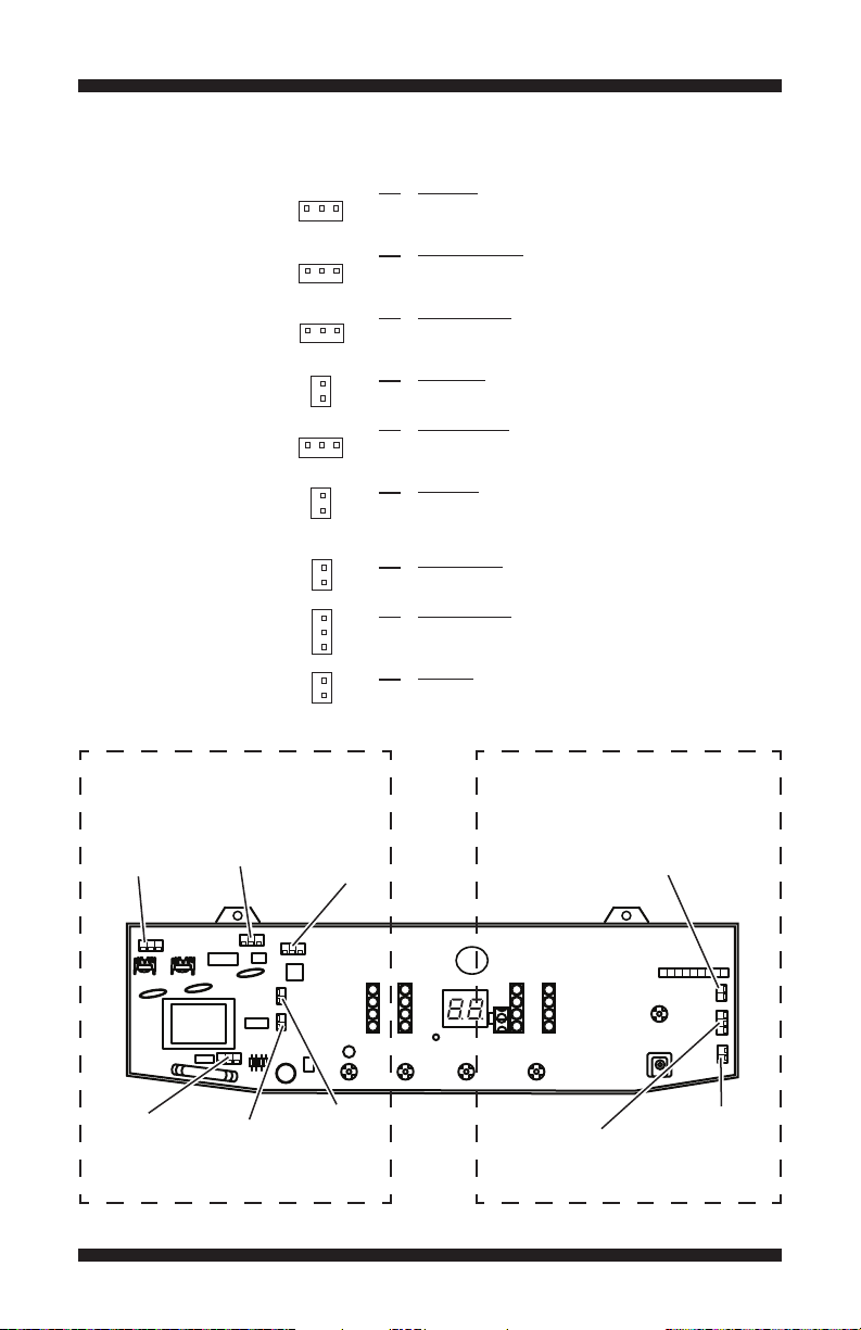
USER INTERFACE/CONTROL BOARD (WASHER)
Board Connectors
and Pinouts
(Figure 2)
CN2
Motor
and
Capacitor
CN5
Lid Lock
Solenoid
1 2 3
Red
1 2 3
White
1 2 3
Yellow
1 2
White
1 2 3
Blue
1 2
Red
2 1
Red
3 2 1 2 1
White
White
CN3
Water Inlet
Valves
High Voltage Connections
CN1 Power Cord
CN1-1 Black L1
CN1-2 Open
CN1-3 Lt Blue Neutral
CN2 Motor and Capacitor
CN2-1 Yellow Main Drive Motor, Right (CW)
CN2-2 Open
CN2-3 Red Main Drive Motor, Left (CCW)
CN3 Water Inlet Valves
CN3-1 Violet Water Inlet Valve, Hot
CN3-2 Open
CN3-3 Orange Water Inlet Valve, Cold
CN4 Torque Motor
CN4-1 Open
CN4-2 Pink Torque Motor
CN5 Lid Lock Solenoid
CN5-1 Gray Interlock
CN5-2 Open
CN5-3 White Interlock
CN9 Drain Pump
CN9-1 Open
CN9-2 Violet Water Pump
Logic/Low Voltage Connections
CN6 Pressure Sensor
CN6-2 White Gnd
CN6-1 Blue Water Level Sensor
CN7 Lid/Lock Switches
CN7-3
Black & Blue
CN7-2 Black Lid Switch ON/OFF
CN7-1 Blue Lock Switch ON/OFF
CN8 Tub Switch
CN8-2 Gray Tub Switch
CN8-1 Gray +5V
+5V
Logic/Low Voltage ConnectorsHigh Voltage Connectors
CN8
Tub Switch
CN1
Power Cord
CN4
Torque Motor
Drain Pump
DO NOT REMOVE OR DESTROY
CN9
Figure 2 - User Interface
CN7
Lid/Lock
Switches
CN6
Pressure
Sensor
PAGE 11
FOR SERVICE TECHNICIAN’S USE ONLY
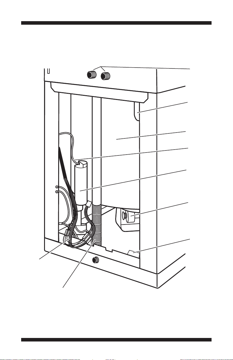
REAR VIEW OF WASHER
Water
Inlet
Valves
Tub
Switch
Tub
Assembly
Pressure
Hose
Pressure
Dome
Connector
Bundle
PAGE 12
Motor &
Retractor
Drain
Pump
Drain
Hose
Figure 3 - Rear View of Washer
DO NOT REMOVE OR DESTROY
 Loading...