

Whirlpool W10726971, W10726970 Installation Instructions

HIGH ALTITUDE KIT INSTALLATION INSTRUCTIONS
W10736252A
To convert single cavity slide-in ranges to elevations above 5000 ft (1524 m).
INSTRUCTIONS D'INSTALLATION POUR TROUSSE
D’UTILISATION EN HAUTE ALTITUDE
Pour la conversion de cuisinières autoportantes à cavité unique à une altitude supérieure
à 5000 pi (1524 m).
Two High Altitude Kits are available for select single cavity slide-in ranges. The choice depends on whether Natural gas or Liquefied
Petroleum (LP) gas will be used. These instructions cover both gases and several range models with many different burners. Each kit
contains orifices which will not be required for your range.
Kit Number W10726970 - Natural Gas (NG) High Altitude
Kit for Slide-in Ranges Contains:
■ 2 - Cooktop spud, Stacked burner NG high altitude
■ 2 - Cooktop spud, Ultra-Rapid burner NG high altitude
■ 2 - Cooktop spud, Semi-Rapid burner NG high altitude
■ 1 - Cooktop spud, Auxi (small) burner NG high altitude
■ 1 - Bake spud, oven bake burner NG high altitude
■ 1 - Broil hood, oven broil burner NG high altitude
■ 1 - Installation instructions
Kit Number W10726971 - Liquefied Petroleum (LP) Gas
High Altitude Kit for Slide-in Ranges Contains:
■ 2 - Cooktop spud, Stacked burner LP high altitude
■ 2 - Cooktop spud, Ultra-Rapid burner LP high altitude
■ 2 - Cooktop spud, Semi-Rapid burner LP high altitude
■ 1 - Cooktop spud, Auxi (small) burner LP high altitude
■ 1 - Bake spud, oven bake burner LP high altitude
■ 1 - Broil hood, oven broil burner LP high altitude
■ 1 - Installation instructions
Pour certaines cuisinières encastrées à cavité unique, deux trousses pour utilisation en haute altitude sont disponibles. L'utilisation de
l'une ou de l'autre dépend du gaz utilisé : naturel ou propane. Ces instructions s'appliquent aux modèles à gaz ainsi qu'à plusieurs
modèles de cuisinières équipées de plusieurs brûleurs différents. Chaque trousse contient des gicleurs qui ne seront pas nécessaires
pour votre cuisinière.
Trousse numéro W10726970 - La trousse pour utilisation
de gaz naturel en haute altitude pour cuisinières
encastrées comprend :
■ 2 gicleurs de table de cuisson, brûleur superposé/gaz
naturel en haute altitude
■ 2 gicleurs de table de cuisson, brûleur ultra rapide/gaz
naturel en haute altitude
■ 2 gicleurs de table de cuisson, brûleur semi rapide/gaz
naturel en haute altitude
■ 1 gicleur de table de cuisson, brûleur auxiliaire (de petite
taille)/gaz naturel en haute altitude
■ 1 gicleur pour cuisson au four, brûleur de cuisson au four/
gaz naturel en haute altitude
■ 1 gicleur pour cuisson au gril, brûleur de cuisson au gril/
gaz naturel en haute altitude
■ 1 Instructions d'installation
Trousse numéro W10726971 - La trousse pour utilisation
de gaz propane en haute altitude pour cuisinières
encastrées comprend :
■ 2 gicleurs de table de cuisson, brûleur superposé/gaz
propane en haute altitude
■ 2 gicleurs de table de cuisson, brûleur ultra rapide/gaz
propane en haute altitude
■ 2 gicleurs de table de cuisson, brûleur semi rapide/gaz
propane en haute altitude
■ 1 gicleur de table de cuisson, brûleur auxiliaire (de petite
taille)/gaz propane en haute altitude
■ 1 gicleur pour cuisson au four, brûleur de cuisson au four/
gaz propane en haute altitude
■ 1 gicleur pour cuisson au gril, brûleur de cuisson au gril/
gaz propane en haute altitude
■ 1 Instructions d'installation
GAS CONVERSION SAFETY
You can be killed or seriously injured if you don't immediately
You
can be killed or seriously injured if you don't
follow
All safety messages will tell you what the potential hazard is, tell you how to reduce the chance of injury, and tell you what can
happen if the instructions are not followed.
Your safety and the safety of others are very important.
We have provided many important safety messages in this manual and on your appliance. Always read and obey all safety
messages.
This is the safety alert symbol.
This symbol alerts you to potential hazards that can kill or hurt you and others.
All safety messages will follow the safety alert symbol and either the word “DANGER” or “WARNING.”
These words mean:
follow instructions.
instructions.
DANGER
WARNING
WARNING: If the information in this manual is not followed exactly, a fire or explosion
may result causing property damage, personal injury or death.
– Do not store or use gasoline or other flammable vapors and liquids in the vicinity of this
or any other appliance.
– WHAT TO DO IF YOU SMELL GAS:
•
Do not try to light any appliance.
•
Do not touch any electrical switch.
•
Do not use any phone in your building.
•
Immediately call your gas supplier from a neighbor's phone. Follow the gas supplier's
instructions.
•
If you cannot reach your gas supplier, call the fire department.
– Installation and service must be performed by a qualified installer, service agency or
the gas supplier.
WARNING: Gas leaks cannot always be detected by smell.
Gas suppliers recommend that you use a gas detector approved by UL or CSA.
For more information, contact your gas supplier.
If a gas leak is detected, follow the “What to do if you smell gas” instructions.
In the State of Massachusetts, the following installation instructions apply:
■
Installations and repairs must be performed by a qualified or licensed contractor, plumber, or gasfitter qualified or licensed by
the State of Massachusetts.
■
If using a ball valve, it shall be a T-handle type.
■
A flexible gas connector, when used, must not exceed 3 feet.
2
GAS CONVERSIONS
†® QUADREX is a registered trademark of NLW Holdings, Inc.
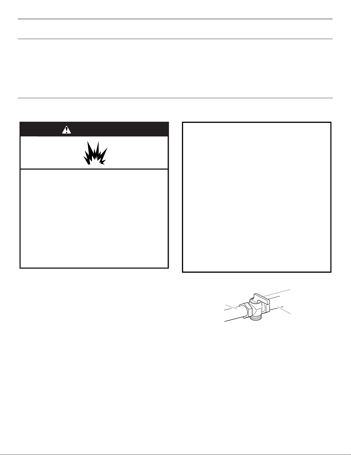
WARNING
Explosion Hazard
Use a new CSA International approved gas supply line.
Install a shut-off valve.
Securely tighten all gas connections.
If connected to LP, have a qualified person make sure
gas pressure does not exceed 14" (36 cm) water
column.
Examples of a qualified person include:
licensed heating personnel,
authorized gas company personnel, and
authorized service personnel.
Failure to do so can result in death, explosion, or fire.
WARNING
This conversion kit shall be installed by a
qualified service agency in accordance
with the manufacturer's instructions and
all applicable codes and requirements of
the authority having jurisdiction. If the
information in these instructions is not
followed exactly, a fire, explosion or
production of carbon monoxide may
result causing property damage, personal
injury or loss of life. The qualified service
agency is responsible for the proper
installation of this kit. The installation is
not proper and complete until the
operation of the converted appliance is
checked as specified in the
manufacturer's instructions supplied with
this kit.
A
B
C
Tools Needed
Gather the required tools before starting installation. Read and
follow the instructions provided with any tools listed here.
Tools Needed
■ ½" combination wrench
■ ⁵⁄₈" combination wrench
■ 7 mm nut driver
Gas Conversions
■ 10 mm nut driver
■ Quadrex
■ Masking tape
■ Plastic bag for replaced parts
®†
or Phillips screwdriver
IMPORTANT: Gas conversions must be done by a qualified
installer. Before proceeding with the conversion, shut off the gas
supply to the range prior to disconnecting the electrical power.
1. Turn the manual shutoff valve to the closed position.
A. To range
B. Manual shutoff valve “closed” position
C. Gas supply line
2. Unplug range or disconnect power.
3
Gas Pressure Regulator
A
A
B
C
D
Side view for Natural Gas
Side view for LP Gas
E
NG
LP
NG
LP
A
A
B
A
C
The gas pressure regulator supplied with this range must be used.
The inlet pressure to the regulator should be as follows for proper
operation:
Natural gas:
Minimum pressure: 6" WCP
Maximum pressure: 14" WCP
LP gas:
Minimum pressure: 11" WCP
Maximum pressure: 14" WCP
Contact local gas supplier if you are not sure about the inlet
pressure.
Burner Input Requirements
Input ratings shown on the model/serial/rating plate are for
elevations up to 2,000 ft (609.6 m).
For elevations above 2,000 ft (609.6 m), ratings are reduced at a
rate of 4% for each 1,000 ft (304.8 m) above sea level (not
applicable for Canada).
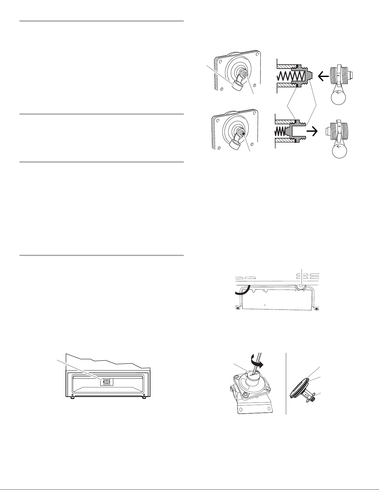
3. Remove plastic cover from gas pressure regulator cap.
4. Turn gas pressure regulator cap counterclockwise with a ⁵⁄₈"
combination wrench to remove.
NOTE: Do not remove the spring beneath the cap.
Gas Supply Pressure Testing
Gas supply pressure for testing regulator must be at least
1" water column pressure above the manifold pressure shown on
the model/serial/rating plate.
Line pressure testing above ½ psi gauge (14" WCP)
The range and its individual shutoff valve must be disconnected
from the gas supply piping system during any pressure testing of
that system at test pressures in excess of ½ psi (3.5 kPa).
Line pressure testing at ½ psi gauge (14" WCP) or lower
The range must be isolated from the gas supply piping system by
closing its individual manual shutoff valve during any pressure
testing of the gas supply piping system at test pressures equal to
or less than ½ psi (3.5 kPa).
To Convert Gas Pressure Regulator
NOTE: Ranges are set for Natural gas from the factory. If you are
using the same type of gas before and after the conversion, the
gas pressure regulator does not need to be converted. Go to the
“To Convert Surface Burners” section.
For Gas Models IGL730C, WEG730H, WEG760H, MGS8880D,
KSGG700E, KSGB900E, and JGS1450D
1. Remove the premium storage drawer, warming drawer or
baking drawer.
2. Locate gas pressure regulator at rear of the drawer
compartment.
NOTE: On models with a warming drawer or baking drawer, an
access cover must be removed to access the gas pressure
regulator.
A. Plastic cover
B. Gas pressure regulator cap with solid end facing out
C. Gas pressure regulator cap with hollow end facing out
D. Washer
E. Gas pressure regulator cap
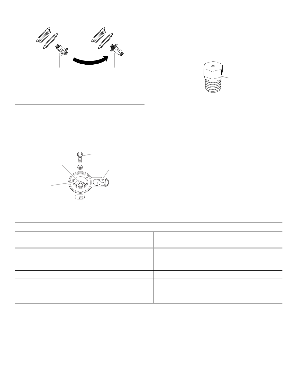
5. Turn over the gas pressure regulator cap and reinstall on
regulator so that the hollow end faces out and the marking
LP” is facing the direction shown in the above drawing.
“
6. Replace plastic cover over gas pressure regulator cap.
For Dual Fuel Models KSDB900E, JDS1450D, KSDG950E, and
JDS1750E
1. Move the range out approximately 1 ft (30.5 cm) from the wall.
2. Locate the gas pressure regulator at the lower right corner on
the back of the range.
A. Gas pressure regulator
IMPORTANT: Do not remove the gas pressure regulator.
3. Unscrew the metal cover and unscrew the blue regulator cap.
Keep the washer in place.
A. Gas pressure regulator
IMPORTANT: Do not remove the gas pressure regulator.
A. Metal cover
B. Washer
C. Blue regulator cap
4
4. Flip the blue regulator cap over and screw it back into the
A
B
B
A
C
D
XXX
A
metal cover.
A. Natural gas position
B. LP gas position
4. Locate the model/serial/rating plate on the range. It will be
located on the oven frame behind the top right side of the oven
door. Identify the burner ratings for this range from the
nameplate.
Refer to the “Natural Gas Orifice Spud Chart for Surface Burners”
or the “LP Gas Orifice Spud Chart for Surface Burners” for the gas
to be used after the conversion. Identify the correct replacement
orifice spuds using the nameplate burner ratings and the color
code on the replacement spuds as shown in the “Natural Gas
Orifice Spud Chart for Surface Burners.”
5. Screw the metal cover securely back into place. Do not
overtighten.
To Convert Surface Burners
1. Remove burner cap.
2. Lift the flame spreader from the burner holder.
3. Apply masking tape to the end of a 7 mm nut driver to help hold
the gas orifice spud in the nut driver while changing it. Press
nut driver down onto the gas orifice spud and remove by
turning it counterclockwise and lifting out. Set gas orifice spud
aside.
A. Orifice spud
B. Orifice spud holder
C. Screw
D. Spark electrode
Natural Gas Orifice Spud Chart for Surface Burners
A. Hex flat
Nameplate Burner Ratings (Sea Level) Replacement Orifice - Natural Gas (High Altitude)
Natural Gas (Btu/hour) Burner Name LP (Btu/hour) Color Code Size Burner Location
19,000/17,000 BTU Stacked 15,000 BTU White/Red - main
Black - simmer
1.70 mm
0.52 mm
Left front
Left front
17,000 BTU Ultra-Rapid 14,200 BTU White/Red 1.70 mm Left front
15,000BTU Ultra-Rapid 14,200 BTU White/Red 1.70 mm Right front
9,200 BTU Semi-Rapid 8,000 BTU White/Brown 1.20 mm Right rear
8,000 BTU Semi-Rapid 8,000 BTU White/Brown 1.20 mm Center
5,000 BTU Auxi 5,000 BTU White/Orange 1.00 mm Left rear
*Same orifices as shipped from factory for Natural gas.
5
 Loading...