


W10355490A

INSTALLATION INSTRUCTIONS
27" (68.6 CM) AND 30" (76.2 CM) ELECTRIC BUILT-IN
CONVECTION MICROWAVE OVEN
INSTRUCTIONS D’INSTALLATION
FOUR À MICRO-ONDES ENCASTRÉ ÉLECTRIQUE
À CONVECTION DE 27" (68,6 CM) ET 30" (76,2 CM)
Table of Contents/Table des matières
BUILT-IN MICROWAVE OVEN SAFETY.......................................2
INSTALLATION REQUIREMENTS................................................3
Tools and Parts ............................................................................3
Location Requirements................................................................3
Electrical Requirements ...............................................................5
INSTALLATION INSTRUCTIONS..................................................6
Prepare Built-In Microwave Oven................................................6
Assemble Spacer Kit....................................................................6
Install Spacer Kit ..........................................................................6
Make Electrical Connection .........................................................6
Install Microwave Oven................................................................8
Complete Installation ...................................................................8
SÉCURITÉ DU FOUR À MICRO-ONDES ENCASTRÉ................9
EXIGENCES D'INSTALLATION...................................................10
Outils et pièces...........................................................................10
Exigences d'emplacement.........................................................10
Spécifications électriques ..........................................................12
INSTRUCTIONS D’INSTALLATION.............................................13
Préparation du four à micro-ondes encastré.............................13
Assemblage de la trousse d'entretoise......................................13
Installation de la trousse d'entretoise ........................................13
Raccordement électrique...........................................................13
Installation du four à micro-ondes .............................................15
Achever l’installation ..................................................................15
W10355490A
BUILT-IN MICROWAVE OVEN SAFETY
Your safety and the safety of others are very important.
We have provided many important safety messages in this manual and on your appliance. Always read and obey all safety
messages.
This is the safety alert symbol.
This symbol alerts you to potential hazards that can kill or hurt you and others.
All safety messages will follow the safety alert symbol and either the word “DANGER” or “WARNING.”
These words mean:
You can be killed or seriously injured if you don't immediately
DANGER
WARNING
All safety messages will tell you what the potential hazard is, tell you how to reduce the chance of injury, and tell you what can
happen if the instructions are not followed.
follow instructions.
can be killed or seriously injured if you don't
You
instructions.
follow
2
INSTALLATION REQUIREMENTS
Tools and Parts
Gather the required tools and parts before starting installation.
Read and follow the instructions provided with any tools listed
here.
Tools ne e ded
■ Phillips screwdriver
■ Measuring tape
■ Level
■ Drill
■ ¹⁄₈" (3.2 mm) drill bit
Parts needed
■ A UL listed or CSA approved conduit connector
■ UL listed wire connectors
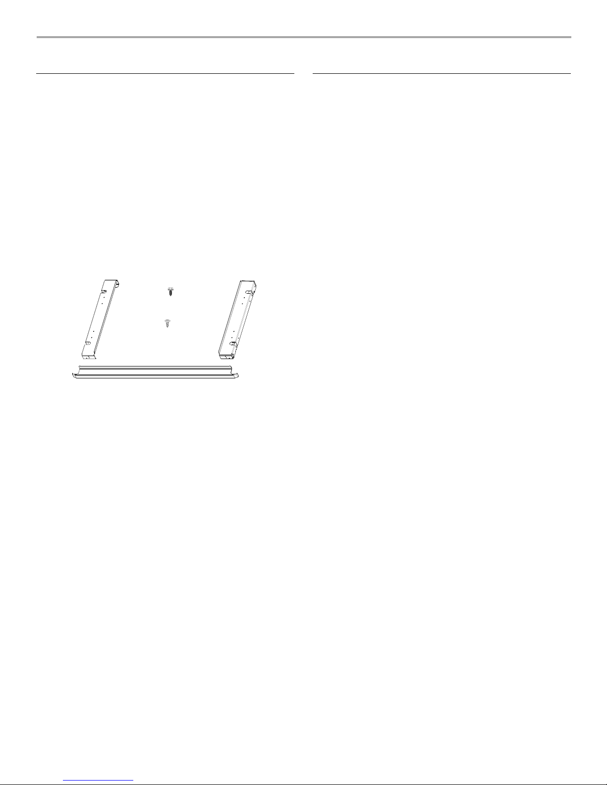
Parts supplied
D
A
C
B
A. Spacer bars (2)
B. Bottom vent (1)
C. Phillips head screws (2)
D. ¾" pan head screws (4)
Check local codes. Check existing electrical supply. See
“Electrical Requirements.”
It is recommended that all electrical connections be made by a
licensed, qualified electrical installer.
A
Location Requirements
IMPORTANT: Observe all governing codes and ordinances.
■ Cabinet opening dimensions that are shown must be used.
Given dimensions provide minimum clearance with
microwave oven.
■ Recessed installation area must provide complete enclosure
around the recessed portion of the microwave oven.
■ Grounded electrical supply is required. See “Electrical
Requirements” section.
■ Electrical supply junction box should be located 3" (7.6 cm)
maximum below the support surface when the microwave
oven is installed in a wall cabinet. A 1" (2.5 cm) minimum
diameter hole should have been drilled in the right rear or left
rear corner of the support surface to pass the appliance cable
through to the junction box.
NOTE: For undercounter installations, it is recommended that
the junction box be located in the adjacent right or left
cabinet. If you are installing the junction box on the rear wall
behind the microwave oven, the junction box must be
recessed and located in the upper or lower right or left corner
of the cabinet. Otherwise, the microwave oven will not fit into
the cabinet opening.
■ For installation above single built-in oven the junction box
must be located inside upper cabinet.
■ If you are installing the junction box on rear wall behind the
microwave oven, the junction box must be recessed and
located in the upper or lower right or left corner of the cabinet;
otherwise, the microwave oven will not fit into the cabinet
opening.
■ Microwave oven support surface must be solid, level and flush
with bottom of cabinet cutout. Floor must be able to support a
weight of 110 lbs (50.0 kg).
IMPORTANT: To avoid damage to your cabinets, check with your
builder or cabinet supplier to make sure that the materials used
will not discolor, delaminate or sustain other damage. This oven
has been designed in accordance with the requirements of UL
and CSA International and complies with the maximum allowable
wood cabinet temperatures of 194°F (90°C).
3
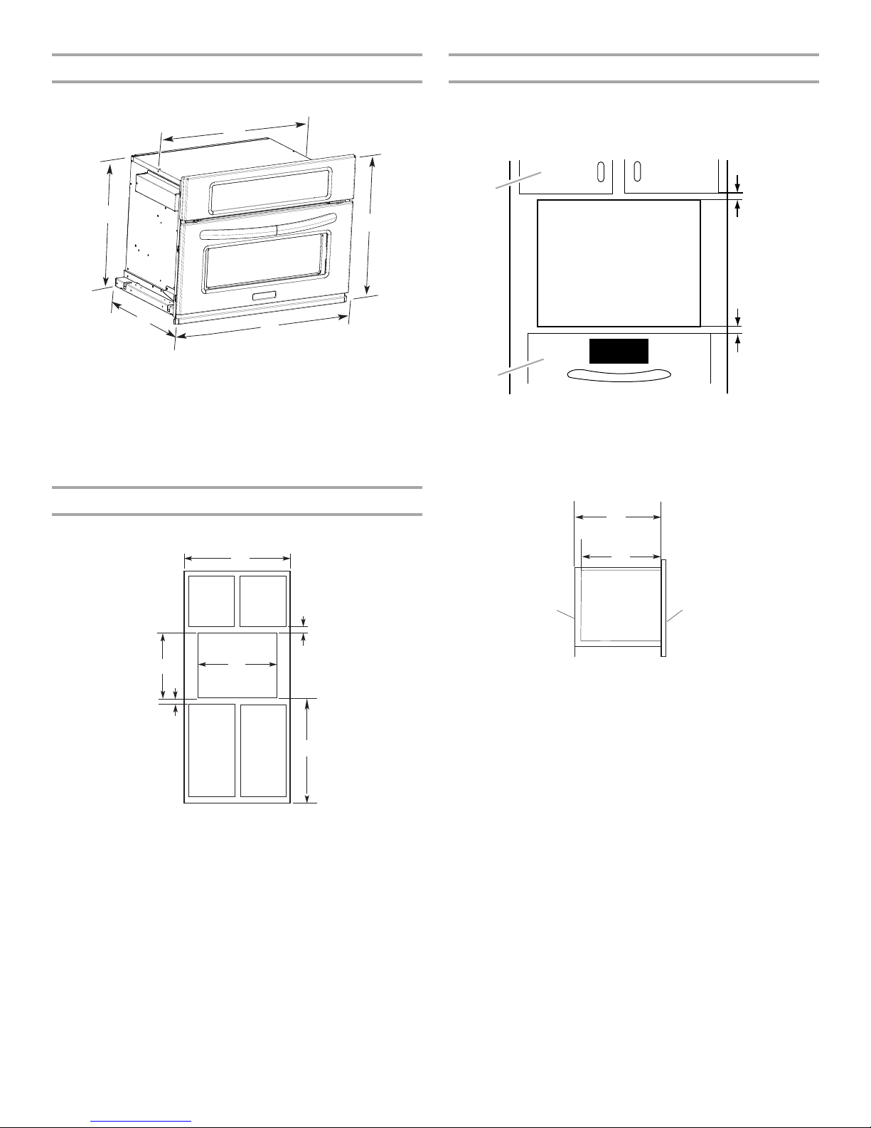
Product Dimensions
Minimum Installation Clearances
27" (68.6 cm) and 30" (76.2 cm) Microwave Ovens
A
E
D
27" (68.6 cm) models
¹⁄₄
" (64.1 cm) recessed width
A. 25
⁵⁄₁₆
" (51.6 cm) overall height
B. 20
C. 26
³⁄₄
" (67.9 cm) overall width
⁷⁄₁₆
" (57.0 cm) max. recessed
D. 22
depth
E. 17
³⁄₄
" (45.1 cm) recessed
height including spacers
C
30" (76.2 cm) models
¹⁄₄
" (71.8 cm) recessed width
A. 28
⁵⁄₁₆
" (51.6 cm) overall height
B. 20
C. 29
³⁄₄
" (75.6 cm) overall width
⁷⁄₁₆
" (57.0 cm) max. recessed
D. 22
depth
E. 17
³⁄₄
" (45.1 cm) recessed
height including spacers
Cabinet Requirements
27" (68.6 cm) and 30" (76.2 cm) Microwave Ovens
For proper installation the following minimum clearances must
exist between the cabinet openings.
Installation Above Single Built-In Oven
A
B
B
A. Upper cabinet
B. Lower single oven*
*Approved models: KEBU107, KEBS107, KEBS177, KEBK101,
KEBK171
Cabinet Side View
A
1"
(2.5 cm)
1"
(2.5 cm)
from top
of oven
F
E
27" (68.6 cm) models
A. 27" (68.6 cm) min. cabinet
width
B. 1" (2.5 cm) top of cutout to
bottom of upper cabinet door
40
" (101.2 cm) bottom of
C.
cutout to floor (recommended)
¹⁄₂
" (64.8 cm) cutout width
D. 25
E. 1
¹⁄₂
" (3.8 cm) min. bottom of
cutout to top of cabinet door
F. 1 9
⁷⁄₁₆
" (49.4 cm) cutout height
A
B
D
C
30" (76.2 cm) models
30
" (76.2 cm) min. cabinet
A.
width
B. 1" (2.5 cm) top of cutout to
bottom of upper cabinet door
40
" (101.2 cm) bottom of
C.
cutout to floor (recommended)
¹⁄₂
" (72.4 cm) cutout width
D. 28
E. 1
¹⁄₂
" (3.8 cm) min. bottom of
cutout to top of cabinet door
F. 1 9
⁷⁄₁₆
" (49.4 cm) cutout height
B
E
¹⁄₄
A. 23
B. 23" (58.4 cm) recessed oven depth
C. Oven front
D. Recessed oven
E. Cabinet
D
" (59.1 cm) min. cutout depth
C
4
Electrical Requirements
GROUNDING INSTRUCTIONS
For a permanently connected microwave oven:
The microwave oven must be connected to a grounded,
metallic, permanent wiring system, or an equipment
grounding conductor should be run with the circuit
conductors and connected to the equipment grounding
terminal or lead on the microwave oven.
Electrical Connection
To properly install your microwave oven, you must determine the
type of electrical connection you will be using and follow the
instructions provided for it here.
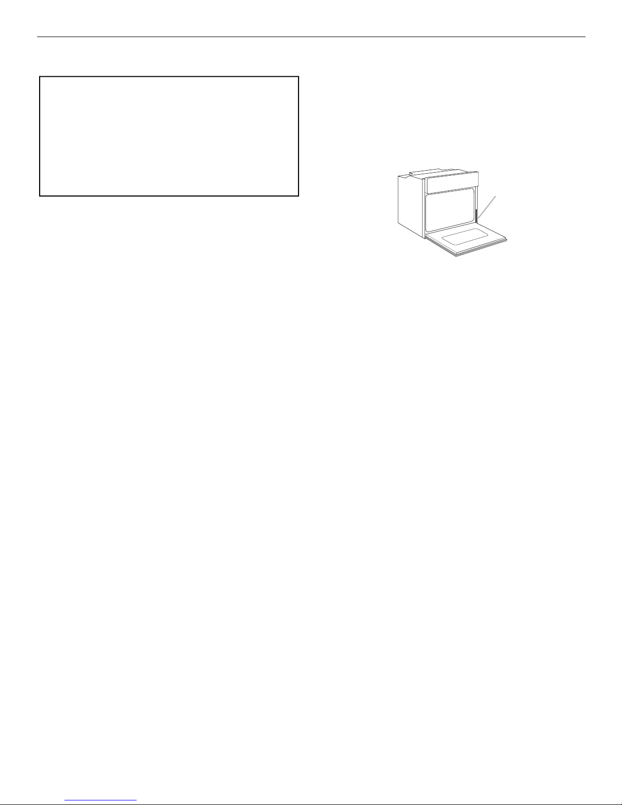
■ Microwave oven must be connected to the proper electrical
voltage and frequency as specified on the model/serial
number rating plate. The model/serial number rating plate is
located on the right-hand microwave oven frame.
SAVE THESE INSTRUCTIONS
If codes permit and a separate ground wire is used, it is
recommended that a qualified electrical installer determine that
the ground path and wire gauge are in accordance with local
codes.
Check with a qualified electrical installer if you are not sure the
microwave oven is properly grounded.
This microwave oven must be connected to a grounded metal,
permanent wiring system.
Be sure that the electrical connection and wire size are adequate
and in conformance with the National Electrical Code, ANSI/
NFPA 70-latest edition or CSA Standards C22.1-94, Canadian
Electrical Code, Part 1 and C22.2 No. O-M91-latest edition, and
all local codes and ordinances.
A copy of the above code standards can be obtained from:
National Fire Protection Association
One Batterymarch Park
Quincy, MA 02269
CSA International
8501 East Pleasant Valley Road
Cleveland, OH 44131-5575
A
A. Model/serial number plate
■ When a 4-wire, single phase 208/220 volt, 60 Hz, AC only
electrical supply is required, a 20-amp maximum circuit
protection is required, fused on both sides of the line.
■ A time-delay fuse or circuit breaker is recommended.
■ Connect directly to the fused disconnect (or circuit breaker
box) through flexible, nonmetallic sheathed, copper cable
(with grounding wire). See “Make Electrical Connection”
section.
■ Flexible cable from the microwave oven should be connected
directly to the junction box.
■ Do not cut the conduit. The length of conduit provided is for
serviceability of the microwave oven.
■ A UL listed or CSA approved conduit connector must be
provided.
■ If the house has aluminum wiring, follow the procedure
below:
1. Connect a section of solid copper wire to the pigtail
leads.
2. Connect the aluminum wiring to the added section of
copper wire using special connectors and/or tools
designed and UL listed for joining copper to aluminum.
Follow the electrical connector manufacturer's recommended
procedure. Aluminum/copper connection must conform with
local codes and industry accepted wiring practices.
5
 Loading...