

Whirlpool UXL5430BSS2, UXL5430BSS1, UXL5430BSS0 Owner’s Manual

30" (76.2 CM) RANGE HOOD LINER
IMPORTANT: READ AND SAVE THESE INSTRUCTIONS.
FOR RESIDENTIAL USE ONLY.
IMPORTANT : LIRE ET CONSERVER CES INSTRUCTIONS.
POUR UTILISATION RÉSIDENTIELLE UNIQUEMENT.
LI30ZC/W10487239D
Installation Instructions and Use & Care Guide
CAISSE DE HOTTE POUR CUISINIÈRE
DE 30" (76,2 CM)
Instructions d’installation et Guide d’utilisation et d’entretien
Table of Contents/Table des matières............................................................................. 2
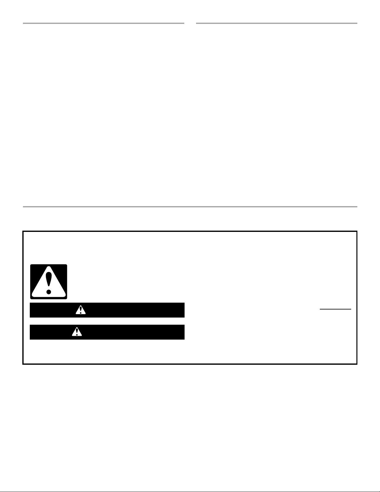
TABLE OF CONTENTS
You can be killed or seriously injured if you don't immediately
You
can be killed or seriously injured if you don't
follow
All safety messages will tell you what the potential hazard is, tell you how to reduce the chance of injury, and tell you what can
happen if the instructions are not followed.
Your safety and the safety of others are very important.
We have provided many important safety messages in this manual and on your appliance. Always read and obey all safety
messages.
This is the safety alert symbol.
This symbol alerts you to potential hazards that can kill or hurt you and others.
All safety messages will follow the safety alert symbol and either the word “DANGER” or “WARNING.”
These words mean:
follow instructions.
instructions.
DANGER
WARNING
TABLE DES MATIÈRES
RANGE HOOD SAFETY .................................................................2
INSTALLATION REQUIREMENTS................................................4
Tools and Parts ............................................................................4
Location Requirements................................................................4
Venting Requirements..................................................................5
Electrical Requirements ...............................................................7
INSTALLATION INSTRUCTIONS..................................................8
Prepare Location..........................................................................8
Install Range Hood.....................................................................10
Connect the Vent System ..........................................................11
Complete Installation .................................................................11
RANGE HOOD USE......................................................................12
Range Hood Controls ................................................................12
RANGE HOOD CARE...................................................................12
Cleaning......................................................................................12
WIRING DIAGRAM .......................................................................14
ASSISTANCE OR SERVICE.........................................................15
In the U.S.A. ...............................................................................15
In Canada ...................................................................................15
Accessories................................................................................15
WARRANTY ..................................................................................15
RANGE HOOD SAFETY
SÉCURITÉ DE LA HOTTE DE CUISINIÈRE................................17
EXIGENCES D'INSTALLATION...................................................19
Outils et pièces...........................................................................19
Exigences d'emplacement.........................................................19
Exigences concernant l’évacuation ...........................................20
Spécifications électriques ..........................................................22
INSTRUCTIONS D’INSTALLATION.............................................23
Préparation de l'emplacement...................................................23
Installation de la hotte ................................................................25
Raccordement du circuit d'évacuation......................................26
Achever l’installation ..................................................................27
UTILISATION DE LA HOTTE .......................................................27
Commandes de la hotte de cuisinière .......................................27
ENTRETIEN DE LA HOTTE..........................................................27
Nettoyage ...................................................................................27
SCHÉMAS DE CÂBLAGE ............................................................29
ASSISTANCE OU SERVICE.........................................................30
Au Canada..................................................................................30
Accessoires ................................................................................30
GARANTIE.....................................................................................31
2

State of California Proposition 65 Warnings:
WARNING: This product contains one or more chemicals known to the State of California to cause cancer.
WARNING: This product contains one or more chemicals known to the State of California to cause birth defects or other
reproductive harm.
IMPORTANT SAFETY INSTRUCTIONS
READ AND SAVE THESE INSTRUCTIONS
WARNING: TO REDUCE THE RISK OF FIRE, ELECTRIC
SHOCK, OR INJURY TO PERSONS, OBSERVE THE
FOLLOWING:
■ Use this unit only in the manner intended by the
manufacturer. If you have questions, contact the
manufacturer.
■ Before servicing or cleaning the unit, switch power off at
service panel and lock the service disconnecting means to
prevent power from being switched on accidentally. When
the service disconnecting means cannot be locked,
securely fasten a prominent warning device, such as a tag,
to the service panel.
■ Installation work and electrical wiring must be done by
qualified person(s) in accordance with all applicable codes
and standards, including fire-rated construction.
■ Do not operate any fan with a damaged cord or plug.
Discard fan or return to an authorized service facility for
examination and/or repair.
■ Sufficient air is needed for proper combustion and
exhausting of gases through the flue (chimney) of fuel
burning equipment to prevent backdrafting. Follow the
heating equipment manufacturer's guideline and safety
standards such as those published by the National Fire
Protection Association (NFPA), the American Society for
Heating, Refrigeration and Air Conditioning Engineers
(ASHRAE), and the local code authorities.
■ When cutting or drilling into wall or ceiling; do not damage
electrical wiring and other utilities.
■ Ducted fans must always be vented outdoors.
CAUTION: For general ventilating use only. Do not use
to exhaust hazardous or explosive materials and vapors.
CAUTION: To reduce risk of fire and to properly exhaust
air, be sure to duct air outside - do not vent exhaust air into
spaces within walls or ceilings, attics or into crawl spaces,
or garages.
WARNING: TO REDUCE THE RISK OF FIRE, USE ONLY
METAL DUCTWORK.
WARNING: TO REDUCE THE RISK OF A RANGE TOP
GREASE FIRE:
■ Never leave surface units unattended at high settings.
Boilovers cause smoking and greasy spillovers that may
ignite. Heat oils slowly on low or medium settings.
■ Always turn hood ON when cooking at high heat or when
flambeing food (i.e. Crepes Suzette, Cherries Jubilee,
Peppercorn Beef Flambé).
■ Clean ventilating fans frequently. Grease should not be
allowed to accumulate on fan or filter.
■ Use proper pan size. Always use cookware appropriate for
the size of the surface element.
WARNING: TO REDUCE THE RISK OF INJURY TO
PERSONS IN THE EVENT OF A RANGE TOP GREASE
FIRE, OBSERVE THE FOLLOWING:
a
■ SMOTHER FLAMES with a close fitting lid, cookie sheet, or
metal tray, then turn off the burner. BE CAREFUL TO
PREVENT BURNS. If the flames do not go out
immediately, EVACUATE AND CALL THE FIRE
DEPARTMENT.
■ NEVER PICK UP A FLAMING PAN - you may be burned.
■ DO NOT USE WATER, including wet dishcloths or towels -
a violent steam explosion will result.
■ Use an extinguisher ONLY if:
– You know you have a class ABC extinguisher, and you
already know how to operate it.
– The fire is small and contained in the area where it
started.
– The fire department is being called.
– You can fight the fire with your back to an exit.
a
Based on "Kitchen Fire Safety Tips" published by NFPA.
■ WARNING: To reduce the risk of fire or electrical shock,
do not use this fan with any solid-state speed control
device.
3

INSTALLATION REQUIREMENTS
†®TORX is a registered trademark of Saturn Fasteners, Inc.
Tools and Parts
Gather the required tools and parts before starting installation.
Read and follow the instructions provided with any tools listed
here.
Tools needed
■ Level
■ Drill
■ ¹⁄₈" (3 mm) drill bit
■ Pencil
■ Pliers
■ Tape measure or ruler
■ Caulking gun and weatherproof caulking compound
■ Phillips screwdriver
■ Flat-blade screwdriver
■ Saber or keyhole saw
■ Vent clamps
■ Metal snips
Parts needed
■ 6" (15.2 cm) round metal vent system
For vented installations, you will need:
■ 1 wall or roof cap
For non-vented (recirculating) installations, you will also
need:
■ Recirculation Kit Part Number W10490330. See the
“Assistance or Service” section to order.
Parts supplied
Remove parts from packages. Check that all parts are included.
■ Damper
■ Hardware package. Includes:
Installation Instructions and Use and Care Guide
2 mounting brackets
6 spacers
10 - 4.5 x 13 mm wood screws
2 - 4.2 x 15 mm machine screws
4 - 3.5 x 9.5 mm flat-head sheet metal screws
8 - 4.2 x 19 mm sheet metal screws
2 - 3.5 x 9.5 mm sheet metal screws
1 - 30" x 12" (76.2 x 30.5 cm) face panel
2 metal grease filters
®†
T10 TORX
8 - metal washers
8 - plastic washers
adapter
Location Requirements
IMPORTANT: Observe all governing codes and ordinances.
Have a qualified technician install the range hood. It is the
installer’s responsibility to comply with installation clearances
specified on the model/serial rating plate. The model/serial rating
plate is located inside the liner behind the filter on the left wall of
the range hood.
Range hood location should be away from strong draft areas,
such as windows, doors, and strong heating vents.
Cabinet opening dimensions that are shown must be used. Given
dimensions provide minimum clearance. Consult your cooktop/
range manufacturer installation instructions before making any
cutouts.
This range hood is recommended for use with cooktops with a
maximum total rating of 65,000 Btus or less.
Grounded electrical outlet is required. See “Electrical
Requirements” section.
The range hood is factory set for vented installations through the
roof or wall. For non-vented (recirculating) installations see “NonVented (recirculating) Installation Through the Soffit/Cabinet” in
the “Prepare Location” section. Recirculation Kit Part Number
W10490330 is available from your dealer or an authorized parts
distributor.
All openings in ceiling and wall where range hood will be installed
must be sealed.
For Mobile Home Installations
The installation of this range hood must conform to the
Manufactured Home Construction Safety Standards, Title 24
CFR, Part 328 (formerly the Federal Standard for Mobile Home
Construction and Safety, title 24, HUD, Part 280) or when such
standard is not applicable, the standard for Manufactured Home
Installation 1982 (Manufactured Home Sites, Communities and
Setups) ANSI A225.1/NFPA 501A, or latest edition, or with local
codes.
4
Product Dimensions
A
I
H
G
F
E
D
C
B
F
A
B
C
D
E
A.
³⁄₈
" (1.0 cm)
B. 30" (76.2 cm) or
36" (91.4 cm)
C. 26" (66.1 cm)
D. 2" (5.1 cm) or
5" (12.7 cm)
E. 10
³⁄₄
" (27.4 cm)
F.
³⁄₄
" (1.9 cm)
G. 11
17
H. 9
I. 13
¹⁄₈
⁷⁄₈
" (30.2 cm) or
⁷⁄₈
" (45.4 cm)
" (23.1 cm)
⁵⁄₈
" (33.7 cm)
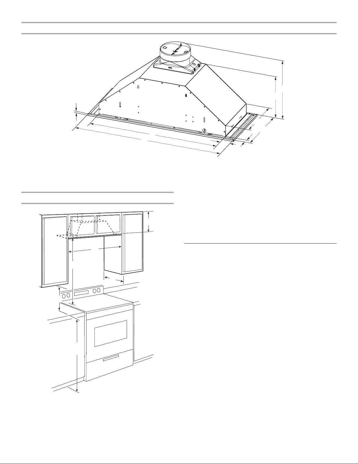
*NOTE: 30" (76.2 cm) cabinet width can be 12" (30.5 cm) deep or
Cabinet Dimensions
18" (45.7 cm) deep cabinets.
36" (91.4 cm) cabinet width requires 18" (45.7 cm) deep
cabinets.
For 18" (45.7 cm) deep cabinets, an optional “Face Panel Rear
Extension” (30" [76.2 cm]) or “Face Panel” (36" [91.4 cm]) must
be purchased separately. See “Assistance and Service” section
to order.
Venting Requirements
(vented models only)
■ Vent system must terminate to the outside, except for non-
vented (recirculating) installations.
■ Do not terminate the vent system in an attic or other enclosed
A. 12" (30.5 cm) min. upper
cabinet height
B. 30" (76.2 cm) or 36" (91.4 cm)
cabinet opening width*
C. 24" (61 cm) min. 36" (91.4 cm)
suggested max. bottom of
cabinet to cooking surface
D. 12" (30.5 cm) cabinet depth*
E. 15" (38.1 cm) min. clearance
upper cabinet to countertop
F. 36" (91.4 cm) base cabinet
height
area.
■ Do not use a 4" (10.2 cm) laundry-type wall cap.
■ Use metal vent only. A rigid metal vent is recommended.
Plastic or metal foil vent is not recommended.
■ The length of the vent system and number of elbows should
be kept to a minimum to provide efficient performance.
For the most efficient and quiet operation:
■ Use no more than three 90° elbows.
■ Make sure there is a minimum of 24" (61.0 cm) of straight
vent between the elbows if more than 1 elbow is used.
■ Do not install 2 elbows together.
■ The vent system must have a damper.
■ Use clamps to seal all joints in the vent system.
■ Use caulking to seal exterior wall or roof opening around the
■ The size of the vent should be uniform.
cap.
5
 Loading...