


LI30LA
LI30LA/W10463244A
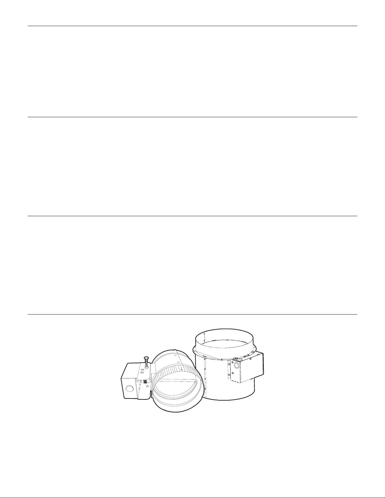
MAKEUP AIR KITS FOR RECTANGULAR (3¼ X 10"
[8.3 X 25.4 CM]) OR ROUND (6, 8 AND 10" [15.2,
20.3 AND 25.4 CM]) VENT DUCT
Installation Instructions and Use & Care Guide
For questions about features, operation/performance, parts, accessories or service, call: 1-800-253-1301
In Canada, call 1-800-807-6777 or visit our website at www.whirlpool.ca
or visit our website at www.whirlpool.com
JUEGOS DE AIRE DE COMPLEMENTO PARA DUCTOS
DE VENTILACIÓN RECTANGULARES
(3¼ X 10" [8,3 X 25,4 CM]) O REDONDOS
(6, 8 Y 10" [15,2, 20,3 Y 25,4 CM])
Instrucciones de instalación y Manual de uso y cuidado
Si tiene preguntas respecto a las características, funcionamiento, rendimiento, partes, accesorios o servicio técnico, llame al: 1-800-253-1301
o visite nuestro sitio de Internet en www.whirlpool.com
ENSEMBLES POUR APPOINT D'AIR POUR CONDUIT
D'ÉVACUATION RECTANGULAIRE
(3¼ X 10" [8,3 X 25,4 CM]) OU ROND
(6, 8 ET 10" [15,2, 20,3 ET 25,4 CM])
Instructions d’installation et Guide d’utilisation et d’entretien
Au Canada, pour assistance, installation ou service, composer
le 1-800-807-6777 ou visiter notre site Web à www.whirlpool.ca
Table of Contents/Índice/Table des matières..................................................................2
IMPORTANT: READ AND SAVE THESE INSTRUCTIONS.
FOR RESIDENTIAL USE ONLY.
IMPORTANTE: LEA Y GUARDE ESTAS INSTRUCCIONES.
SÓLO PARA USO RESIDENCIAL.
IMPORTANT : LIRE ET CONSERVER CES INSTRUCTIONS.
POUR UTILISATION RÉSIDENTIELLE UNIQUEMENT.
TABLE OF CONTENTS
VENT SYSTEM SAFETY.................................................................2
INSTALLATION REQUIREMENTS................................................4
Tools and Parts ............................................................................4
Location Requirements................................................................ 4
Electrical Requirements ...............................................................5
INSTALLATION INSTRUCTIONS..................................................6
Prepare Location..........................................................................6
Install Makeup Air Switch Duct....................................................6
Install Motorized Damper.............................................................7
ÍNDICE
SEGURIDAD DEL SISTEMA DE VENTILACIÓN........................12
REQUISITOS DE INSTALACIÓN.................................................14
Herramientas y piezas................................................................14
Requisitos de ubicación.............................................................14
Requisitos eléctricos..................................................................15
INSTRUCCIONES DE INSTALACIÓN.........................................16
Preparación de la ubicación ......................................................16
Instalación del conducto conmutador de aire
de complemento ........................................................................16
TABLE DES MATIÈRES
SÉCURITÉ DES CIRCUITS DE VENTILATION...........................22
EXIGENCES D'INSTALLATION...................................................24
Outils et pièces...........................................................................24
Exigences d'emplacement.........................................................24
Spécifications électriques..........................................................25
INSTRUCTIONS D’INSTALLATION ............................................26
Préparation de l'emplacement...................................................26
Installation du conduit du commutateur de débit d'air de
compensation.............................................................................26
Make Electrical Connection .........................................................7
Check Operation ..........................................................................8
Makeup Air Kit Maintenance........................................................8
WIRING DIAGRAM .........................................................................9
ASSISTANCE OR SERVICE.........................................................10
In the U.S.A. ...............................................................................10
In Canada ...................................................................................10
WARRANTY ..................................................................................11
Instalación del regulador de tiro motorizado .............................17
Haga la conexión del suministro eléctrico.................................18
Verifique el funcionamiento........................................................19
Mantenimiento del juego de aire de complemento...................19
DIAGRAMA DE CABLEADO........................................................20
AYUDA O SERVICIO TÉCNICO...................................................21
En los EE.UU. .............................................................................21
GARANTÍA.....................................................................................21
Installation du clapet motorisé...................................................27
Raccordement électrique...........................................................28
Contrôle du fonctionnement ......................................................29
Maintenance de l'ensemble d'air de compensation..................29
SCHÉMA DE CÂBLAGE...............................................................30
ASSISTANCE OU SERVICE.........................................................31
Au Canada..................................................................................31
GARANTIE.....................................................................................31
VENT SYSTEM SAFETY
Your safety and the safety of others are very important.
We have provided many important safety messages in this manual and on your appliance. Always read and obey all safety
messages.
This is the safety alert symbol.
This symbol alerts you to potential hazards that can kill or hurt you and others.
All safety messages will follow the safety alert symbol and either the word “DANGER” or “WARNING.”
These words mean:
You can be killed or seriously injured if you don't immediately
DANGER
WARNING
All safety messages will tell you what the potential hazard is, tell you how to reduce the chance of injury, and tell you what can
happen if the instructions are not followed.
2
follow instructions.
can be killed or seriously injured if you don't
You
instructions.
follow

IMPORTANT SAFETY INSTRUCTIONS
WARNING: TO REDUCE THE RISK OF FIRE, ELECTRIC
SHOCK, OR INJURY TO PERSONS, OBSERVE THE
FOLLOWING:
■ Use this unit only in the manner intended by the
manufacturer. If you have questions, contact the
manufacturer at the address or telephone number listed in
this document.
■ Before servicing or cleaning the unit, switch power off at
service panel and lock the service disconnecting means to
prevent power from being switched on accidentally. When
the service disconnecting means cannot be locked,
securely fasten a prominent warning device, such as a tag,
to the service panel.
■ Installation work and electrical wiring must be done by
qualified person(s) in accordance with all applicable codes
and standards, including fire-rated construction codes and
standards.
■ Sufficient air is needed for proper combustion and
exhausting of gases through the flue (chimney) of fuel
burning equipment to prevent back drafting. Follow the
heating equipment manufacturer's guideline and safety
standards such as those published by the National Fire
Protection Association (NFPA), the American Society for
Heating, Refrigeration and Air Conditioning Engineers
(ASHRAE), and the local code authorities.
■ When performing installation, servicing or cleaning the unit,
it is recommended to wear safety glasses and gloves.
■ When cutting or drilling into wall or ceiling, do not damage
electrical wiring or other hidden utilities.
■ Ducted fans must always be vented outdoors.
■ This unit is not designed to provide combustion air for fuel
burning appliances.
■ Do not connect the unit directly to a combustion appliance
of any type.
■ During extreme weather events including snow storms,
ensure that the intake area for the outside air duct is not
blocked and able to provide a clear pathway for outside air
to enter the system.
WARNING: TO REDUCE THE RISK OF FIRE, USE ONLY
METAL DUCTWORK.
CAUTION: For general ventilating use only. Do not use to
exhaust hazardous or explosive materials and vapors.
CAUTION: To reduce risk of fire and to properly exhaust
air, be sure to duct air outside - do not vent exhaust air into
spaces within walls or ceilings, attics or into crawl spaces, or
garages.
■ When notching or drilling into framing including floor
supports, rim joists, and wall studs, comply with code and
manufacturer limitations on allowable modifications to these
structural members.
■ This unit is intended to be installed within the home in a
location protected from moisture.
■ This unit must be in an accessible location which allows for
inspection of the unit.
■ When federal, provincial or state legislation comprises more
restrictive installation and/or certification requirements, the
aforementioned requirements prevail on those of this
document and the installer agrees to conform to these at
his own expense.
CAUTION:
■ Do not locate outside air inlet near hazardous materials or
explosives.
■ Unit shall not be installed to introduce air from crawl
spaces, garages, attics, adjacent dwelling units, or other
locations within the building shell. Unit shall be installed to
introduce air directly from outdoors.
■ Do not run the outside air duct directly above or closer than
2 ft (0.6 m) to any furnace or its supply plenum, boiler, or
other heat producing appliance.
■ Any ductwork used in conjunction with the damper must be
installed in compliance with all local and national codes that
are applicable.
■ Do not operate the damper for fresh air introduction until all
system filters, including the central duct system filter, have
been installed per the system design.
■ Please read the unit specification label on the product for
further information and requirements.
■ The damper’s outdoor air intake, ducting, and any filters
should be inspected and maintained on a regular basis.
■ Insulate the duct and damper to prevent build-up of
condensation in cold weather climates. Vapor barriers on
both sides of insulation are recommended.
READ AND SAVE THESE INSTRUCTIONS
3
INSTALLATION REQUIREMENTS
)
Tools and Parts
Gather the required tools and parts before starting installation.
Read and follow the instructions provided with any tools listed
here.
Tool s ne ede d
■ Drill with 1¼" (3.0 cm) drill bit
■ Pencil
■ Wire stripper or utility knife
■ Tape measure or ruler
■ Pliers
■ Caulking gun and weatherproof caulking compound
■ Jigsaw or keyhole saw
■ Flat-blade screwdriver
■ Metal snips
■ Phillips screwdriver
Parts needed (quantities of parts are determined by
installation requirements)
■ Home power supply cable
■ Vent clamps
■ Wall or roof cap
■ 6" (15.2 cm) diameter vent duct for connection to motorized
damper. (Lengths are determined by installation
requirements.)
■ UL listed wire connectors
■ ½" (12.7 mm) UL listed or CSA approved strain relief
Parts supplied
Remove parts from packages. Check that all parts are included.
3¼ x 10" (8.3 x 25.4 cm) Rectangular Makeup Air Kit
(W10446914)
■ 3¼ x 10" (8.3 x 25.4 cm) makeup air switch duct
■ 6" (15.2 cm) motorized damper
†
■ T10 Torx
6" (15.2 cm) Round Makeup Air Kit (W10446915)
■ 6" (15.2 cm) round makeup air switch duct
■ 6" (15.2 cm) motorized damper
■ T10 Torx
8" (20.3 cm) Round Makeup Air Kit (W10446916)
■ 8" (20.3 cm) round makeup air switch duct
■ 6" (15.2 cm) motorized damper
■ T10 Torx
10" (25.4 cm) Round Makeup Air Kit (W10446917)
■ 10" (25.4 cm) round makeup air switch duct
■ 2 - 6" (15.2 cm) motorized damper
■ T10 Torx
®
adapter
†
®
adapter
†
®
adapter
†
®
adapter
Location Requirements
IMPORTANT: Observe all governing codes and ordinances.
Have a qualified technician install this makeup air kit. It is the
installer's responsibility to comply with installation clearances
specified.
Grounded electrical outlet is required. See “Electrical
Requirements” section.
All openings in ceiling and wall must be sealed.
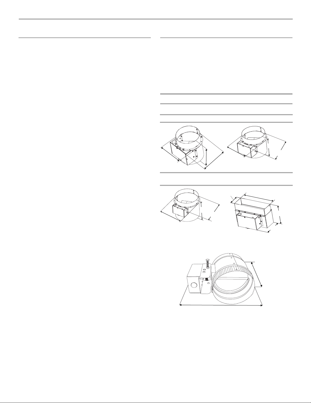
Product Dimensions
Makeup Air Switch Duct (installed on the range hood)
6" (15.2 cm) Kit W10446915 8" (20.3 cm) Kit W10446916
7⁹⁄₁₆"
(19.2 cm)
6"
9¹⁵⁄₁₆"
(25.2 cm
5⁷⁄₈"
(14.9 cm)
5¹⁵⁄₁₆"
(15.1 cm)
7¹⁄₈"
6¹³⁄₁₆"
(17.2 cm)
10" (25.4 cm) Kit
W10446917
10¹⁵⁄₁₆"
(27.7 cm)
(18 cm)
(17.6 cm)
9⁹⁄₁₆"
(24.3 cm)
6¹⁵⁄₁₆"
12"
(30.4 cm)
8⁷⁄₈"
(22.5 cm)
3¼" x 10" (8.3 x 25.4 cm) Kit
W10446914
3¹⁄₄"
(8 cm)
10"
(25.4 cm)
6" (15.2 cm) Motorized Damper (installed for outside air
intake)
(15.2 cm)
9¹⁄₂"
(24 cm)
®†TORX is a registered trademark of Saturn Fasteners, Inc.
4
Planning the Installation
Motorized Damper and Outside Air Connected Directly to a
Ceiling, Floor or Wall Register
Planning the Makeup Air Switch Duct installation
This makeup air kit can only be used with vented range hoods.
The makeup air kit must match the vent transition size for your
range hood.
Planning the Motorized Damper installation
Planning the installation first requires selecting the most
appropriate installation approach. The following illustrations offer
suggestions for the most effective installation approach by
considering a few important factors.
Typical Installations
Installations will vary according to the location in the home where
the motorized damper is installed and which makeup air kit is
used. The following illustrations can be used as a reference guide
for your installation. Always comply with all governing codes and
ordinances.
NOTE: The 10" (25.4 cm) round Makeup Air Kit must be installed
with 2 independent incoming air supply ducts. Use the
2 motorized dampers supplied with the kit (1 each, in the
incoming fresh air supply ducts).
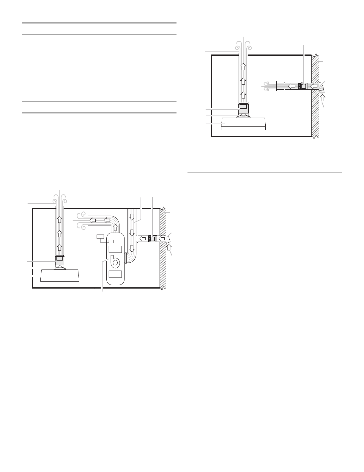
Motorized Damper Connected to Return Side of Central Duct
System
FG
D
H
I
C
B
A
A. Range hood
B. Vent transition
C. Makeup air switch duct
D. Range hood exhaust
E. HVAC system
E
F. Return air central system
G. Motorized damper
H. Wall or roof
I. Wall/roof cap
J. Outside air
J
E
D
F
G
C
B
H
A
A. Range hood
B. Vent transition
C. Makeup air switch duct
D. Range hood exhaust
E. Motorized damper
F. Wall or roof
G. Wall/roof cap
H. Outside air
Electrical Requirements
Observe all governing codes and ordinances.
Ensure that the electrical installation is adequate and in
conformance with National Electrical Code, ANSI/NFPA 70 (latest
edition), or CSA Standards C22.1-94, Canadian Electrical Code,
Part 1 and C22.2 No. 0-M91 (latest edition) and all local codes
and ordinances.
If codes permit and a separate ground wire is used, it is
recommended that a qualified electrician determine that the
ground path is adequate.
A copy of the above code standards can be obtained from:
National Fire Protection Association
■ A 120 volt, 60 Hz., AC only, 15-amp, fused electrical circuit is
required.
■ If the house has aluminum wiring, follow the procedure
below:
1. Connect a section of solid copper wire to the pigtail
leads.
2. Connect the aluminum wiring to the added section of
copper wire using special connectors and/or tools
designed and UL listed for joining copper to aluminum.
Follow the electrical connector manufacturer's recommended
procedure. Aluminum/copper connection must conform with
local codes and industry accepted wiring practices.
■ Wire sizes must conform to the requirements of the National
Electrical Code, ANSI/NFPA 70 (latest edition), or CSA
Standards C22. 1-94, Canadian Electrical Code, Part 1 and
C22.2 No. 0-M91 (latest edition) and all local codes and
ordinances.
■ A UL or CSA listed strain relief must be provided at each end
of the power supply cable/conduit (at the junction boxes).
1 Batterymarch Park
Quincy, MA 02169-7471
CSA International
8501 East Pleasant Valley Road
Cleveland, OH 44131-5575
5
INSTALLATION INSTRUCTIONS
C
B
C
B
Prepare Location
■ It is recommended that the Makeup Air Kit is installed at the
same time the range hood is installed.
■ If the range hood is already installed, you will need to remove
the vent covers and the vent duct system from the range
hood. Consult your hood manual. (See illustrations in the
“Install Makeup Air Switch Duct” section.)
■ Makeup air switch duct must be assembled to vent duct in
the vertical (upward) position only.
4. Install the range hood using the Installation Instructions that
came with range hood.
NOTE: If range hood is already installed, replace the vent
system onto the makeup air switch duct and seal
connections with vent clamps.
10" (25.4 cm) Round Makeup Air Switch Duct (From kit
W10446917)
1. Disconnect power.
2. If range hood is installed, remove the vent system and its vent
covers and put them aside.
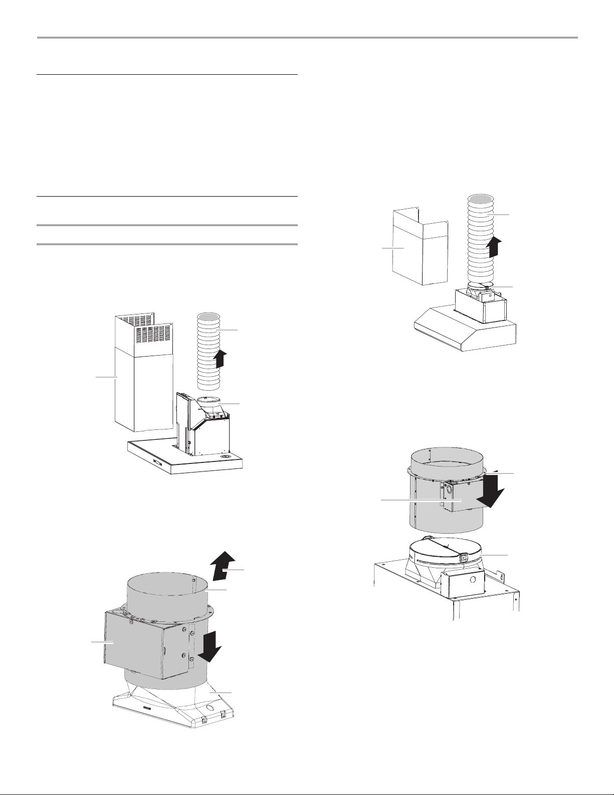
Install Makeup Air Switch Duct
Wall or Island Mount Range Hood Models
6" (15.2 cm) and 8" (20.3 cm) Round Makeup Air Switch Duct
(From kits W10446915 and W10446916)
1. Disconnect power.
2. If range hood is installed, remove the vent system and its vent
covers and put them aside.
B
A
A. Vent covers
B. Vent system
C. Vent transition
B
A
A. Vent covers
B. Vent system
C. Vent transition
3. Install the makeup air switch duct to the vent transition and
seal connection with vent clamp.
NOTE: The terminal box should be oriented to either the right
or left side of the hood for wiring access.
A
3. Install the makeup air switch duct to the vent transition and
seal connection with vent clamp. The terminal box cover
should be to the front or to either side for wiring access.
C
A
D
A. Terminal box cover
B. Airflow
C. Makeup air switch duct
D. Vent transition
6
C
A. Terminal box cover
B. Makeup air switch duct
C. Vent transition
4. Install the range hood using the Installation Instructions that
came with range hood.
NOTE: If range hood is already installed, replace the vent
system onto the makeup air switch duct and seal
connections with vent clamps.
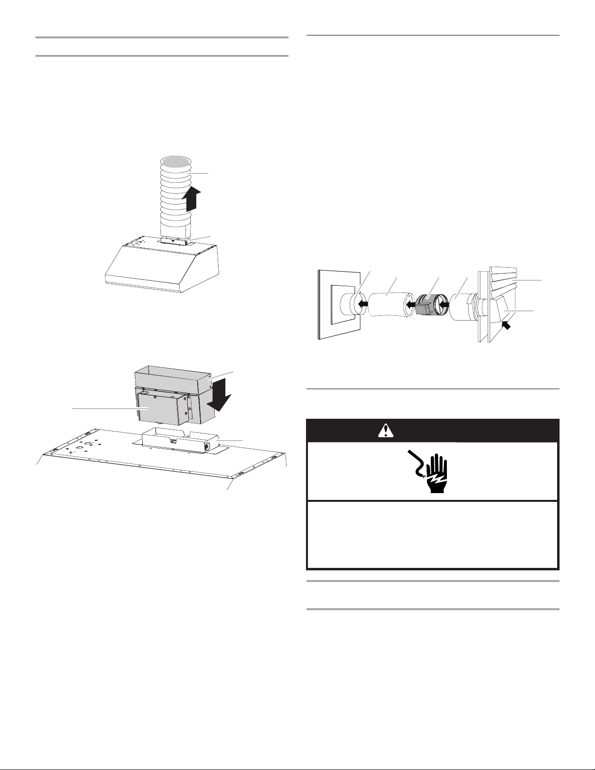
Under-Cabinet Mount Range Hood Models
D
3¼" x 10" (8.3 x 25.4 cm) Rectangular Makeup Air Switch
Duct (From kit W10446914)
NOTE: The range hood must be mounted before the makeup air
switch duct is attached. Use the Installation Instructions that
came with the range hood.
1. Disconnect power.
2. If range hood is installed, remove the vent system and put it
aside.
A
B
Install Motorized Damper
IMPORTANT: Observe all governing codes and ordinances.
Proper location of the outside air intake is necessary to ensure
that the damper can reliably allow fresh air to enter the home. The
following requirements for the location of the outside air intake
must be met:
■ Outside air intake is to be located a minimum of 10 ft (3.05 m)
from combustion appliance vents, chimneys, plumbing
stacks, and bathroom, laundry, or kitchen exhaust vents.
■ Outside air intake is to be placed high enough above grade to
prevent blockage from snow or other debris such as leaves,
and at a minimum of 1 ft (30.5 cm) above grade.
■ The damper should be installed to draw air directly from
outdoors. Makeup air should not be drawn from crawl
spaces, garages, attics, adjacent dwelling units, or any
enclosed part of the building.
Install the motorized damper as shown. See the illustrations in
“Typical Installations” in the “Location Requirements” section for
reference.
A
B
B
C
A. Vent system
B. Vent transition
3. Install the makeup air switch duct to the vent transition and
seal connection. The terminal box cover should be to the
front for wiring access.
B
A
C
A. Terminal box cover
B. Makeup air switch duct
C. Vent transition
4. Install the vent system onto the makeup air switch duct and
seal connections. Finalize the installation of the range hood
using the Installation Instructions that came with range hood.
E
F
A. Wall register
B. Ducts
C. 6" (15.2 cm) motorized damper
D. Wall/roof
E. Wall or roof cap
F. A i r f l o w
Make Electrical Connection
WARNING
Electrical Shock Hazard
Disconnect power before servicing.
Replace all parts and panels before operating.
Failure to do so can result in death or electrical shock.
To Remove and Install Motorized Damper Terminal Box
Cover
1. Press in and lift up on the end of terminal box cover with wire
hole to remove cover.
2. To install terminal cover, place tab on solid end of cover into
small slot in motor mount, swing cover over motor and slip
second tab into larger slot.
7
Make the Electrical Connection
1. Disconnect power.
2. Determine the location where the wiring conduit will be
routed through the ceiling or wall between the makeup air
switch duct and the motorized damper.
3. Drill a hole at this location.
4. Locate the electrical terminal boxes in the makeup air switch
duct and the motorized damper.
Remove the terminal box covers and set the covers and
screws aside.
5. Determine the knockouts in terminal boxes for motorized
damper, makeup air switch duct and house junction box that
will be used.
Remove knockouts and install a ½" (12.7 mm) UL listed or
CSA approved strain relief at each location.
6. Run separate wiring between the house junction box and the
terminal boxes for the motorized damper and the makeup air
switch duct.
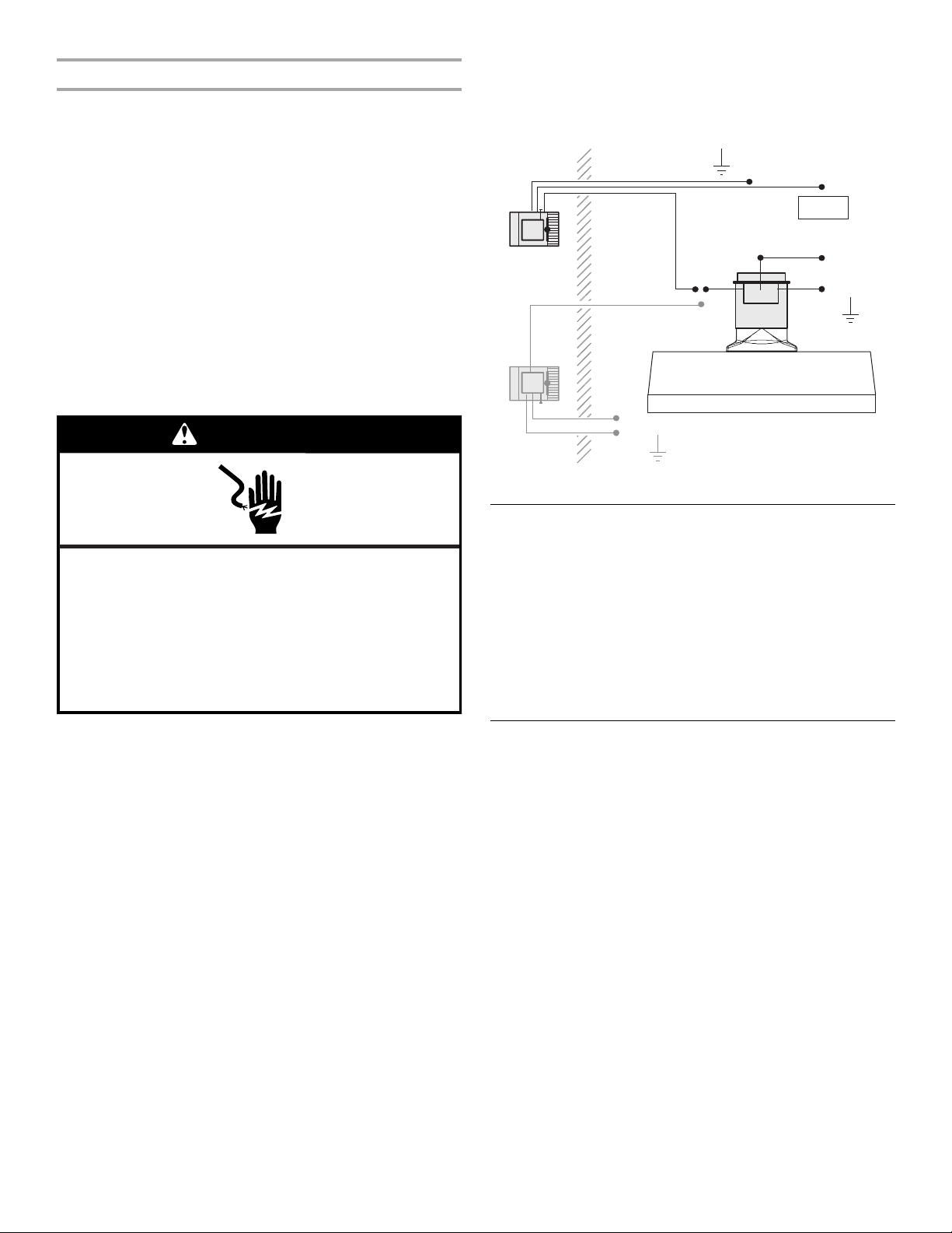
WARNING
10. Connect the white wire(s) from the motorized damper to the
house neutral white wire(s) using UL listed wire connectors.
NOTE: The 10" (25.4 cm) Makeup Air Kit must be installed
with 2 motorized dampers. The lightest figure shown is the
connection for the second motorized damper.
wall
green
black
black
House
white
green
10" (25.4 cm) Makeup air installation
neutral
House
ground
white
brown
House
ground
black
black
neutral
120VAC
yellow/
green
ground
House
House
line
House
Electrical Shock Hazard
Disconnect power before servicing.
Connect ground wire to green ground wire in terminal
box.
Replace all parts and panels before operating.
Failure to do so can result in death, fire, or
electrical shock.
7. Connect green (yellow/green) wires from makeup air switch
duct and motorized damper to house ground using UL listed
wire connectors.
8. Connect brown wire from makeup air switch duct to the black
wire(s) from the motorized damper using UL listed wire
connectors.
9. Connect black wire from makeup air switch duct to the house
line black wire using a UL listed wire connector.
Check Operation
Once the make up air switch duct and the motorized damper(s)
are installed, the installer should confirm that the motorized
damper opens and closes in conjunction with signals from the
hood.
■ The motorized damper should close or be closed when
the range hood speed switch is Off or On at low speed.
■ The motorized damper should open when the range hood
speed switch is set at medium speed or higher.
A qualified HVAC contractor should also ensure the proper
operation and venting of all combustion equipment in the home.
Makeup Air Kit Maintenance
Regular maintenance is necessary to ensure the proper operation
of the makeup air system. Failure to conduct routine maintenance
can reduce the ability of the damper to introduce fresh air into the
home. Regular maintenance should include the following
activities:
■ Maintain a clear opening at the outdoor end cap, keeping
snow, leaves or vegetation from building up at the end
cap.
■ Clean or replace the interior filter(s) that serve to filter
fresh air before it enters the home.
■ During regular HVAC maintenance, have the mechanical
contractor inspect the damper system for proper
operation.
8
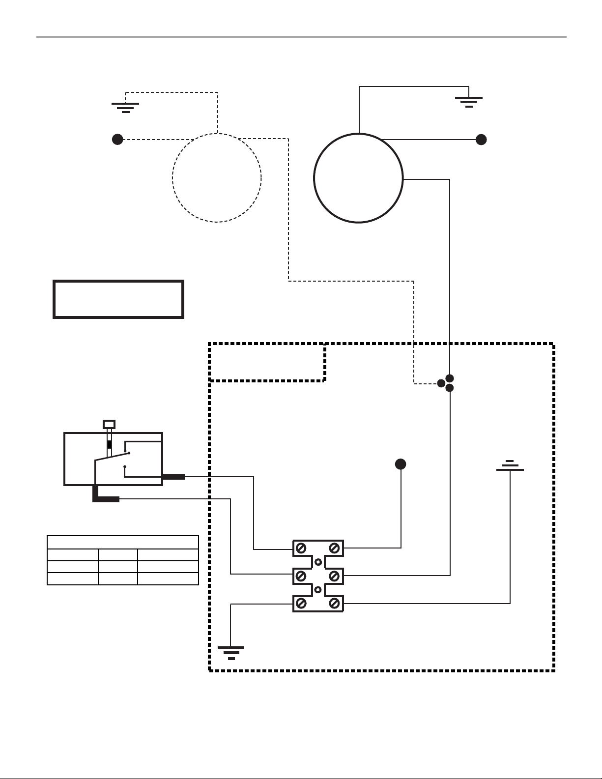
WIRING DIAGRAM
Ground
(to house)
Neutral
(to house)
(for round 10" [25.4 cm] applications)
SE12R A
Activation microswitch
G
W
M
Motorized damper #2
Makeup air switch
duct terminal box
BK
M
Motorized damper
G
W
BK
(between motorized
damper and makeup air
switch duct terminal box)
Ground
(to house)
Neutral
(to house)
Line
COM
SWITCH OPERATION
Position
N.C. - COM
N.O. - COM
N.C.
N.O.
Function Voltage
Off
On
N/A
120 VAC 60 Hz
BK
BR
Y/G
Connections block
(to house)
BK
BR
Y/G
Line
Ground
(to house)
9

ASSISTANCE OR SERVICE
When calling for assistance or service, please know the purchase
date and the complete model and serial number of your
appliance. This information will help us to better respond to your
request.
If you need replacement parts
If you need to order replacement parts, we recommend that you
use only factory specified parts. Factory specified parts will fit
right and work right because they are made with the same
precision used to build every new appliance. To locate factory
specified replacement parts in your area, call us or your nearest
designated service center.
In the U.S.A.
Call the Whirlpool Customer eXperience Center
toll free: 1-800-253-1301.
Our consultants provide assistance with:
■ Features and specifications on our full line of appliances.
■ Installation information.
■ Use and maintenance procedures.
■ Accessory and repair parts sales.
■ Specialized customer assistance (Spanish speaking, hearing
impaired, limited vision, etc.).
■ Referrals to local dealers, repair parts distributors and service
companies. Whirlpool designated service technicians are
trained to fulfill the product warranty and provide afterwarranty service, anywhere in the United States.
To locate the Whirlpool designated service company in your
area, you can also look in your telephone directory Yellow
Pages.
In Canada
Call the Whirlpool Canada LP Customer eXperience Centre toll
free: 1-800-807-6777.
Our consultants provide assistance with:
■ Features and specifications on our full line of appliances.
■ Use and maintenance procedures.
■ Accessory and repair parts sales.
■ Referrals to local dealers, repair parts distributors, and
service companies. Whirlpool Canada LP designated service
technicians are trained to fulfill the product warranty and
provide after-warranty service, anywhere in Canada.
For further assistance
If you need further assistance, you can write to Whirlpool
Canada LP with any questions or concerns at:
Customer eXperience Centre
Whirlpool Canada LP
200 - 6750 Century Ave.
Mississauga, Ontario L5N 0B7
Please include a daytime phone number in your correspondence.
For further assistance
If you need further assistance, you can write to Whirlpool
Corporation with any questions or concerns at:
Whirlpool Brand Home Appliances
Customer eXperience Center
553 Benson Road
Benton Harbor, MI 49022-2692
Please include a daytime phone number in your correspondence.
10
 Loading...