


KR-32
Whirlpool KR-32, SF195LEK, SF341BEK, SF356BEK, SF357PEK User Manual
...
CONSUMER SERVICES TECHNICAL
EDUCATION GROUP PRESENTS
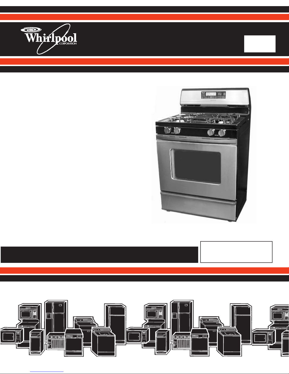
30″ FREESTANDING
SELF-CLEANING
GAS RANGE
KR-32
JOB AID
Part No. 8178025

FORWARD
This Whirlpool Job Aid, “30˝ Freestanding Self-Cleaning Gas Range,” (Part No. 8178025),
provides the technician with information on the installation and service of the Freestanding SelfCleaning Gas Range. It is to be used as a training Job Aid and Service Manual. For specific
information on the model being serviced, refer to the “Use and Care Guide,” or “Tech Sheet”
provided with the gas range.
The Wiring Diagrams and Strip Circuits used in this Job Aid are typical and should be used for
training purposes only. Always use the Wiring Diagram supplied with the product when servicing
the unit.
GOALS AND OBJECTIVES
The goal of this Job Aid is to provide detailed information that will enable the service technician to
properly diagnose malfunctions and repair the Whirlpool 30˝ Freestanding Self-Cleaning Gas
Range.
The objectives of this Job Aid are to:
• Understand and follow proper safety precautions.
• Successfully troubleshoot and diagnose malfunctions.
• Successfully perform necessary repairs.
• Successfully return the gas range to its proper operational status.
WHIRLPOOL CORPORATION assumes no responsibility for any repairs made
on our products by anyone other than Authorized Service Technicians.
Copyright © 2001, Whirlpool Corporation, Benton Harbor, MI 49022
- ii -

TABLE OF CONTENTS
Page
GENERAL............................................................................................................................... 1-1
Important Safety Information ............................................................................................. 1-1
Whirlpool Model & Serial Number Designations ................................................................ 1-2
Model & Serial Number Label And Tech Sheet Locations................................................. 1-3
Specifications..................................................................................................................... 1-4
Whirlpool Gas Range Warranty ....................................................................................... 1-14
INSTALLATION INFORMATION ........................................................................................... 2-1
L.P. Gas Conversion.......................................................................................................... 2-1
Installing The Anti-Tip Bracket ........................................................................................... 2-5
THEORY OF OPERATION ..................................................................................................... 3-1
AccuBake VS. AccuBake Duo Cooking Systems .............................................................. 3-1
Warming Drawer ................................................................................................................ 3-3
Soft Close Door ................................................................................................................. 3-4
COMPONENT ACCESS ......................................................................................................... 4-1
Component Locations ........................................................................................................ 4-1
Removing A Sealed Burner & Ignitor ................................................................................. 4-2
Removing An Ignition Switch & Gas Valve ........................................................................ 4-4
Removing The Cooktop ..................................................................................................... 4-6
Removing The Door Latch & The Door Switch .................................................................. 4-7
Removing The Broil & Bake Burners & Ignitors ................................................................. 4-9
Removing The Warming Drawer Element & Temperature Sensor .................................. 4-11
Removing The Oven Light Socket Assembly .................................................................. 4-13
Removing The Control Power Supply, The Electronic Oven Control,
& The Direct Spark Ignition Control .............................................................................. 4-14
Removing The Latch Drive .............................................................................................. 4-16
Removing The Oven Temperature Sensors .................................................................... 4-17
Removing The Gas Distribution Valve ............................................................................. 4-18
Removing The Power Cord ............................................................................................. 4-19
Removing The Oven Door ............................................................................................... 4-20
Removing The Oven Door Handle & Glass ..................................................................... 4-22
Removing The Oven Door Gasket................................................................................... 4-24
Removing A Side Panel ................................................................................................... 4-25
COMPONENT TESTING ........................................................................................................ 5-1
Ignition Switches ................................................................................................................ 5-1
Door Switch ....................................................................................................................... 5-2
Warming Drawer Element.................................................................................................. 5-2
Latch Drive......................................................................................................................... 5-3
Oven & Warming Drawer Temperature Sensors ............................................................... 5-3
The Gas Distribution Valve ................................................................................................ 5-4
- iii -

Page
DIAGNOSIS & TROUBLESHOOTING ................................................................................... 6-1
Failure/Error Display Codes—Tech Sheet 8522648.......................................................... 6-1
WIRING DIAGRAMS & STRIP CIRCUITS ............................................................................. 7-1
Wiring Diagram .................................................................................................................. 7-1
Strip Circuits ...................................................................................................................... 7-2
TECH TIPS ............................................................................................................................. 8-1
Duo Cooking System Flow Chart....................................................................................... 8-1
- iv -
GENERAL
WARNING
IMPORTANT SAFETY INFORMATION
Your safety and the safety of others is very important.
Important safety messages have been provided in this Job Aid. Always read and obey all
safety messages.
This is the safety alert symbol.
This symbol alerts you to hazards that can kill or hurt you
and others.
All safety messages will be preceded by the
safety alert symbol and the word “WARNING.”
All safety messages will identify the hazard, tell
you how to reduce the chance of injury, and tell
you what can happen if the instructions are not
followed.
WARNING
ELECTRICAL SHOCK HAZARD
Disconnect power before servicing.
Replace all panels before operating.
Failure to do so could result in death or
electrical shock.
WARNING
FIRE HAZARD
Shut off gas supply line valve before servicing the range.
Check all gas line connections and replace
all panels before operating the range.
Failure to do so could result in explosion, fire,
or other injury.
ELECTROSTATIC DISCHARGE
(ESD) SENSITIVE ELECTRONICS
ESD problems are present everywhere. ESD
may damage or weaken the electronic control
assembly. The new control assembly may appear to work well after repair is finished, but
failure may occur at a later date due to ESD
stress.
• Use an antistatic wrist strap. Connect the
wrist strap to a green ground connection
point or unpainted metal in the appliance;
or touch your finger repeatedly to a green
ground connection point or unpainted metal
in the appliance.
PERSONAL INJURY HAZARD
To prevent tipping, install range anti-tip
bracket.
Save the installation instructions. If the range
is moved to a new location, the anti-tip bracket
must be removed and reinstalled in the new
location.
Failure to follow these instructions could
result in serious injury.
• Before removing the part from its package, touch the antistatic bag to a green
ground connection point or unpainted metal
in the appliance.
• Avoid touching electronic parts or terminal
contacts. Handle the electronic control
assembly by the edges only.
• When repackaging the failed electronic
control assembly in an antistatic bag, observe the above instructions.
1-1

WHIRLPOOL MODEL & SERIAL NUMBER DESIGNATIONS
MODEL NUMBER
MODEL NUMBER S F 3 4 1 B E K W
INTERNATIONAL SALES IND.
OR MARKETING CHANNEL
IF PRESENT
PRODUCT GROUP:
R = ELECTRIC RANGES
S = GAS RANGES
G = WHIRLPOOL GOLD
PRODUCT IDENTIFICATION:
A = ACCESSORY K = KITS
B = BUILT-IN M = MV COMBO
C = COOKTOP S = SET-IN
E = EYE-LEVEL W = SLIDE-IN GAS
F = FREESTANDING Y = SLIDE-IN ELECTRIC
H = HOODS
MODEL SIZE:
0 = 20˝ OR 24˝ FREESTANDING
1 = 30˝ IMPERIAL SERIES FREESTANDING (1996 & LATER)
2 = 30˝ FREESTANDING (1996 & LATER)
3 = 30˝ FREESTANDING
4 = 40˝ FREESTANDING
5 = 36˝ FREESTANDING
6 = 30˝ SET-IN RANGES
OVEN TYPES:
0 THRU 3 = STANDARD PORCELAIN
2 THRU 5 = CONTINUOUS CLEAN (BEFORE 1996)
4 THRU 9 = PYROLYTIC SELF-CLEAN
FEATURE / VARIATIONS:
ELECTRIC
0, 1, 2, 5, 7 = COIL ELEMENTS
4 = STANDARD PATTERN CERAMIC
6, 8, 9 = DELUXE PATTERN CERAMIC
GAS
0, 1, 2, 3, 4, 6 = OPEN BURNER
5 & 7 = SEALED BURNER
DOOR TYPE:
B = SOLID BLACK GLASS
L = LARGE WINDOW
O = METAL OVEN DOOR
P = STANDARD WINDOW GLASS
FEATURE CODE:
E = ELECTRONIC IGNITION (GAS ONLY)
S = STANDING IGNITION (GAS ONLY)
C = COLOR COORDINATED GLASS (BEFORE 1998)
X = NOT DEFINED
YEAR OF INTRODUCTION:
H = 1999. J = 2000, K = 2001
COLOR CODE:
B = BLACK W = WHITE P = PANORAMIC
N = ALMOND Z = ALMOND ON ALMOND
Q = WHITE ON WHITE T = BISCUIT
S = STAINLESS STEEL V = BISCUIT W / BLACK DOOR / PANEL
SERIAL NUMBER
SERIAL NUMBER R K 49 10196
MANUFACTURING SITE
R = TULSA, OKLAHOMA
YEAR OF PRODUCTION:
K = 2000, L = 2001, M = 2002
WEEK OF PRODUCTION:
49th WEEK
PRODUCT SEQUENCE NUMBER
1-2
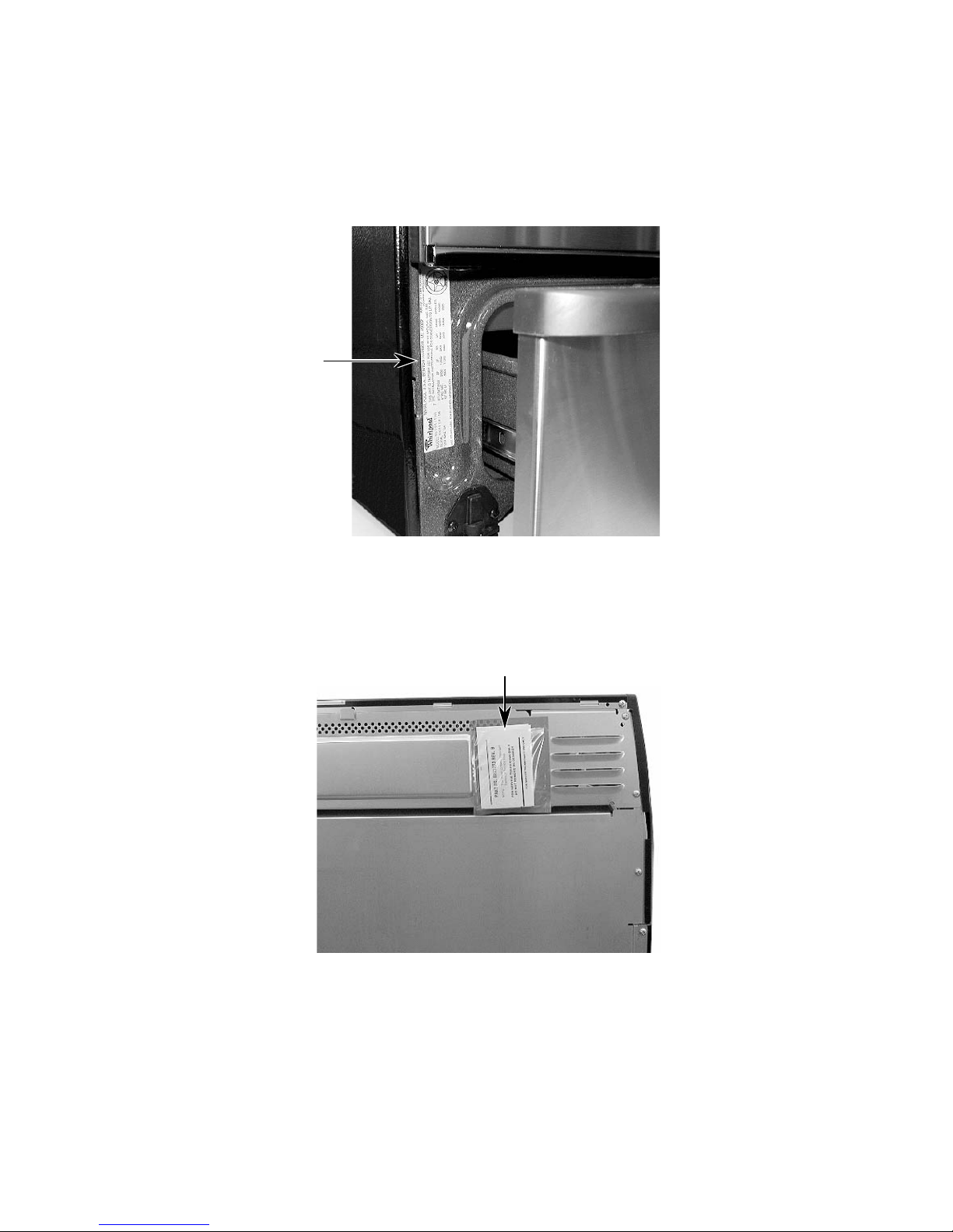
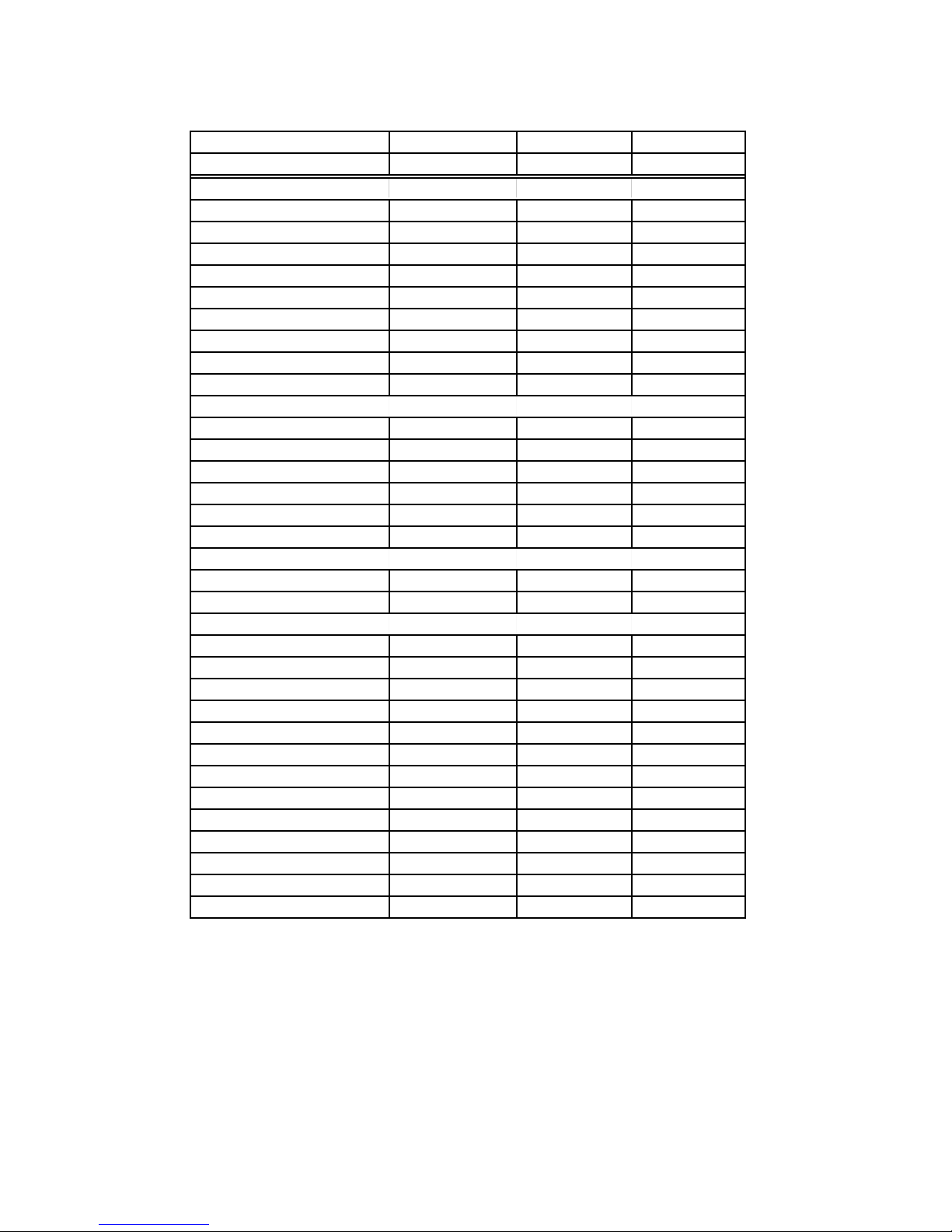
MODEL & SERIAL NUMBER LABEL
AND TECH SHEET LOCATIONS
The Model/Serial Number label and Tech Sheet locations are shown below.
Model & Serial
Number Location
Tech Sheet Location
(On Top Rear Cover)
1-3
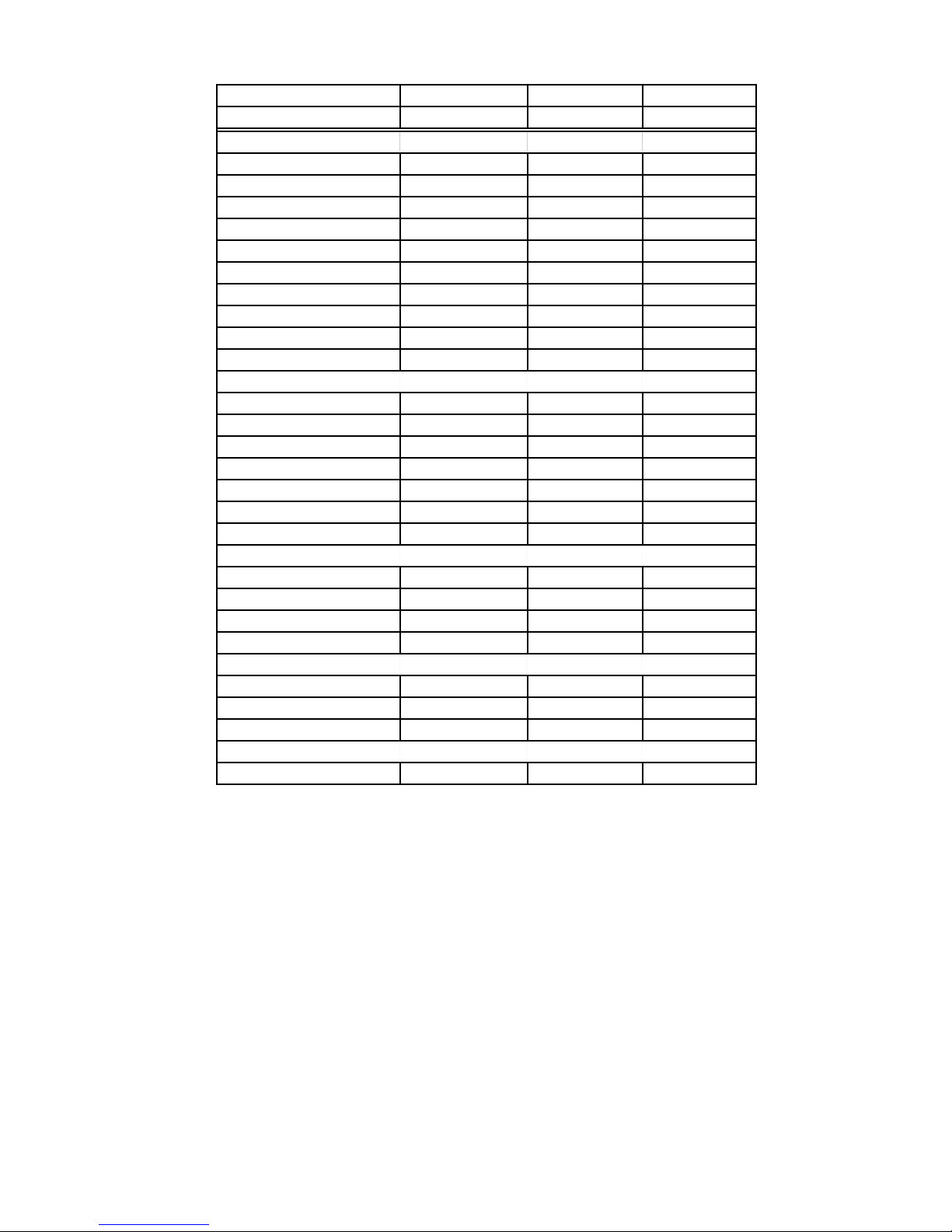
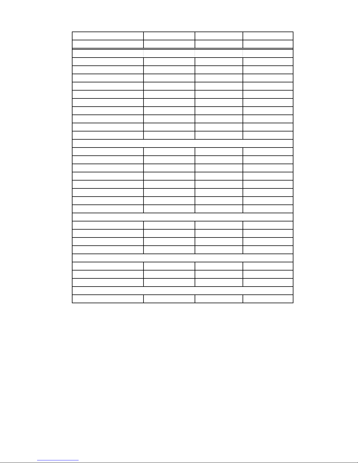
SPECIFICATIONS
Gas Model Number SF195LEK SF341BEK SF356BEK
Color W / Q / T / B / Z W W / V / Q / B
GENERAL INFORMATION
Cleaning System
Burner Type
Valve Degrees
Oven Window & Size
Broiler Type
Oven Controls
Oven Light
Special Features
DIMENSIONS
Height-Overall
Height to Maintop
Depth
Depth to Manifold Panel
Width
Approx Shipping Weight
BACKGUARD FEATURES
Safety Gas Shutoff
Oven Heating Light Indicator
COOKTOP FEATURES
Burner Type
Ignition
Gas Valves
Burner BTU: Right Front
Burner BTU: Left Front
Burner BTU: Right Rear
Burner BTU: Left Rear
L.P. Convertible(included)
Grate Type
Center Grate
Knobs (Color Coord w/ Manifold)
Accusimmer Knob
Power Burner Knob
Self-Clean Self-Clean Self-Clean
Sealed Sealed Sealed
270deg 270 deg 270 deg
XL window No No
Waist High Waist High Waist High
EZ600 Knob 150 EZ150
Yes No Yes
13.5 PB No clock opening Clock/Timer
Accubake 2 No No
46.8" 46.8" 46.8"
36" 36" 36"
25" 25" 25"
25.0" 25.0" 25.0"
29.875" 29.875" 29.875"
190 183 183
No No No
in Oven Control in Oven Control in Oven Control
Sealed Sealed Sealed
Electronic Electronic Electronic
270deg 270 deg 270 deg
9,500 BTU 9,500 BTU 9,500 BTU
PB - 13,500 BTU 9,500 BTU 9,500 BTU
5,000 BTU 5,000 BTU 5,000 BTU
8,000 BTU 9,500 BTU 8,000 BTU
Yes-Spud Yes-Spud Yes-Spud
Cast Iron Whr Stmpd Stl Whr Stmpd Stl
Ye s No No
WHR Heavy duty WHR Barrel WHR Barrel
Yes No No
Yes No No
1-4
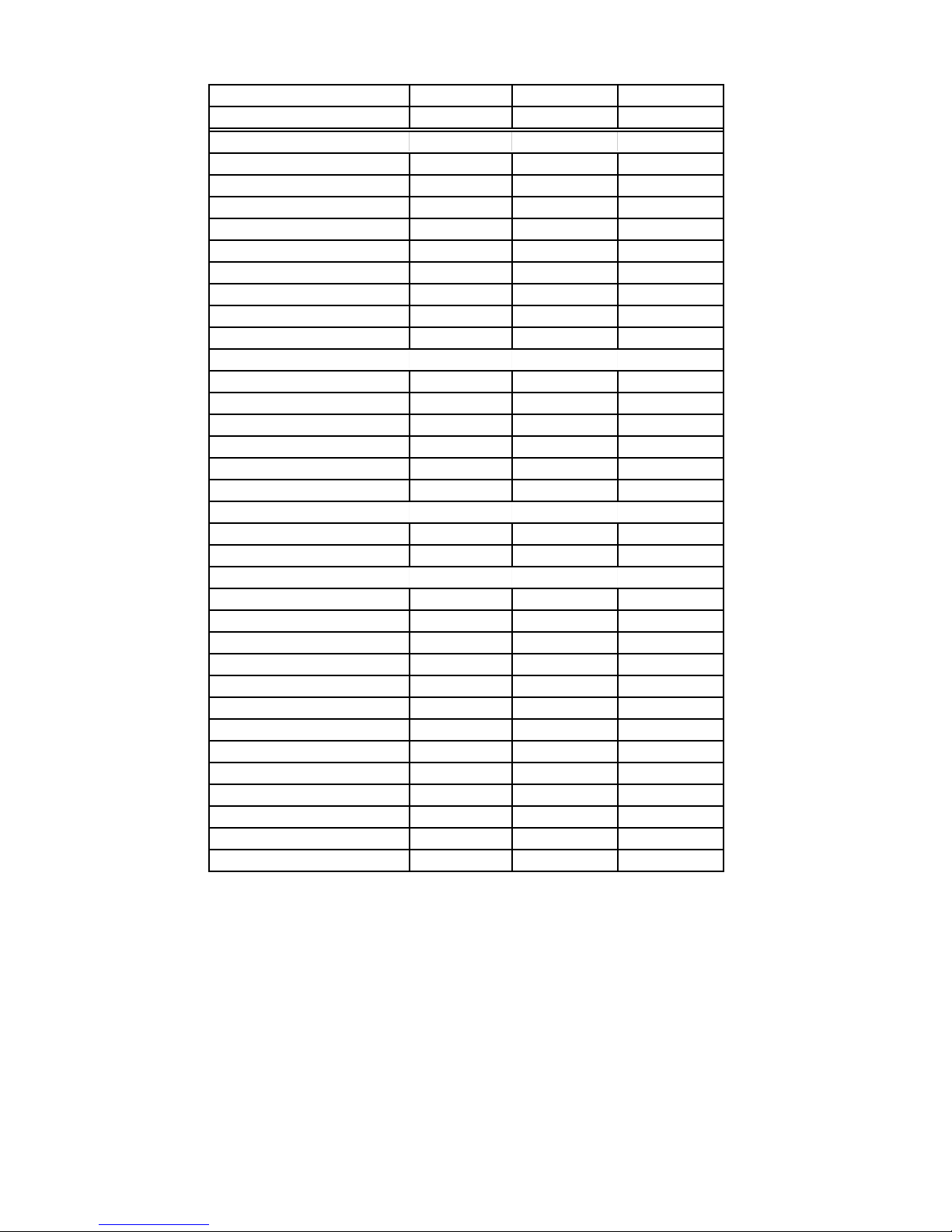
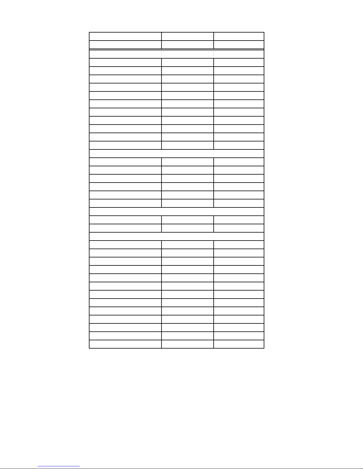
Gas Model Number SF195LEK SF341BEK SF356BEK
Color W / Q / T / B / Z W W / V / Q / B
OVEN FEATURES
Oven Type
Oven Width
Oven Height
Oven Depth
Warm Hold
Broiler Output
Bake Output
Oven Light in Cavity
Auto Oven Light Switch
Manual Oven Light Switch
Self-Clean Self-Clean Self-Clean
24.25" 24.25" 24.25"
17.5" 17.5" 17.5"
19.0" 19.0" 19.0"
Yes No No
10,000 BTU 10,000 BTU 10,000 BTU
16,500 BTU 16,500 BTU 16,500 BTU
Yes #REF! #REF!
Yes No No
Yes-Rocker No No
LOWER PANEL/DRAWER
Lower Storage Drawer
Drawer Liner
Drawer Width
Drawer Height
Drawer Depth
Glides
Handle Type
Yes no - panel only no - panel only
Yes No No
12.7 n/a n/a
3.0 n/a n/a
16.3 n/a n/a
Rollers n/a n/a
Drawn Handle n/a n/a
LITERATURE
Use & Care Guide
Tech Sheet
Installation Instructions
Service Manual
Yes Yes Yes
Yes Yes Yes
Yes Yes Yes
8178025 8178025 8178025
OTHER SPECIFICATIONS
AGA Approval
Anti-Tip Device Approved
Anti-Tip Shipped w/ Unit
Yes Yes Yes
Floor Brkt/Wall Brkt Floor Brkt/Wall Brkt Floor Brkt/Wall Brkt
Floor Bracket Floor Bracket Floor Bracket
ACCESSORIES
Griddle n/a n/a
1-5
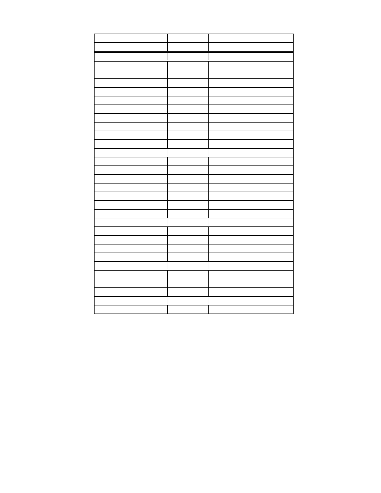
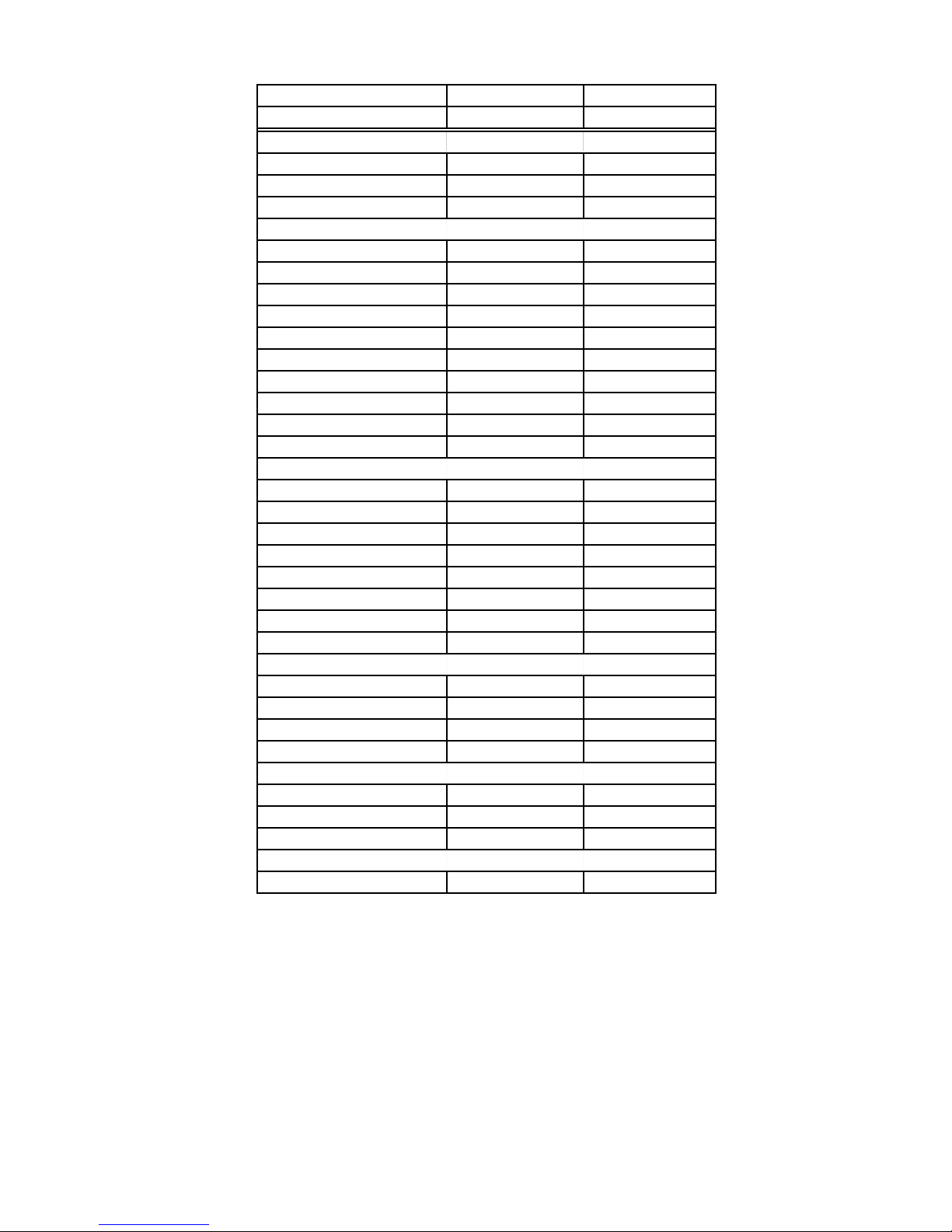
Gas Model Number SF357PEK SF367PEK SF369LEK
Color W / V / Q / T W / V / Q / T Q / T
GENERAL INFORMATION
Cleaning System
Burner Type
Valve Degrees
Oven Window & Size
Broiler Type
Oven Controls
Oven Light
Special Features
Self-Clean Self-Clean Self-Clean
Sealed Sealed Sealed
270 deg 270deg 270deg
Yes-Std XL window XL window
Waist High Waist High Waist High
EZ150 EZ151 EZ150
Yes Yes Yes
Clock/Timer Clock/Timer Clock/Timer
n/a 12.5 PB 13.5 PB
DIMENSIONS
Height-Overall
Height to Maintop
Depth
Depth to Manifold Panel
Width
Approx Shipping Weight
46.8" 46.8" 46.8"
36" 36" 36"
25" 25" 25"
25.0" 25.0" 25.0"
29.875" 29.875" 29.875"
183 190 190
BACKGUARD FEATURES
Safety Gas Shutoff
Oven Heating Light Indicator
No No No
in Oven Control in Oven Control in Oven Control
COOKTOP FEATURES
Burner Type
Ignition
Gas Valves
Burner BTU: Right Front
Burner BTU: Left Front
Burner BTU: Right Rear
Burner BTU: Left Rear
L.P. Convertible(included)
Grate Type
Center Grate
Knobs (Color Coord w/ Manifold)
Accusimmer Knob
Power Burner Knob
Sealed Sealed Sealed
Electronic Electronic Electronic
270 deg 270deg 270deg
9,500 BTU 9,500 BTU 9,500 BTU
9,500 BTU PB - 12,500 BTU PB - 13,500 BTU
5,000 BTU 5,000 BTU 5,000 BTU
8,000 BTU 8,000 BTU 8,000 BTU
Yes-Spud Yes-Spud Yes-Spud
Whr Stmpd Stl Whr Stmpd Stl Whr Stmpd Stl
No No No
Roper handle Roper handle WHR Barrel
No No No
No No Yes
1-6
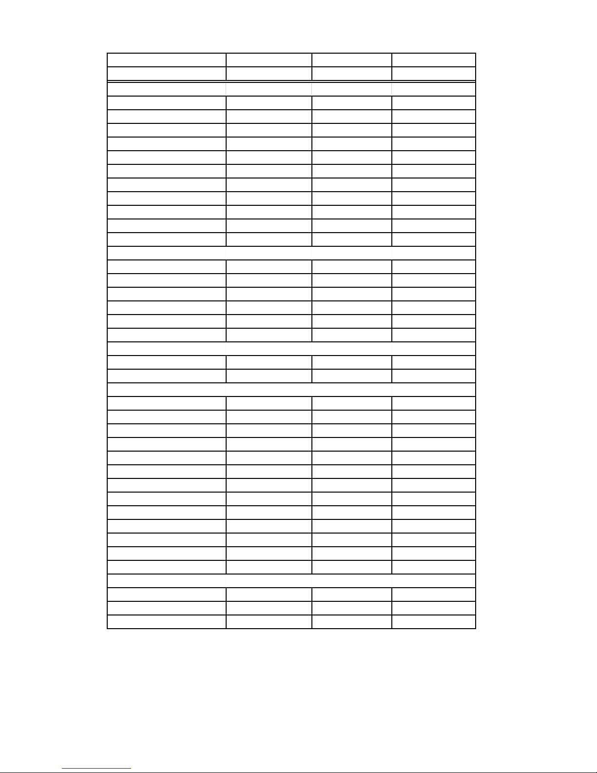
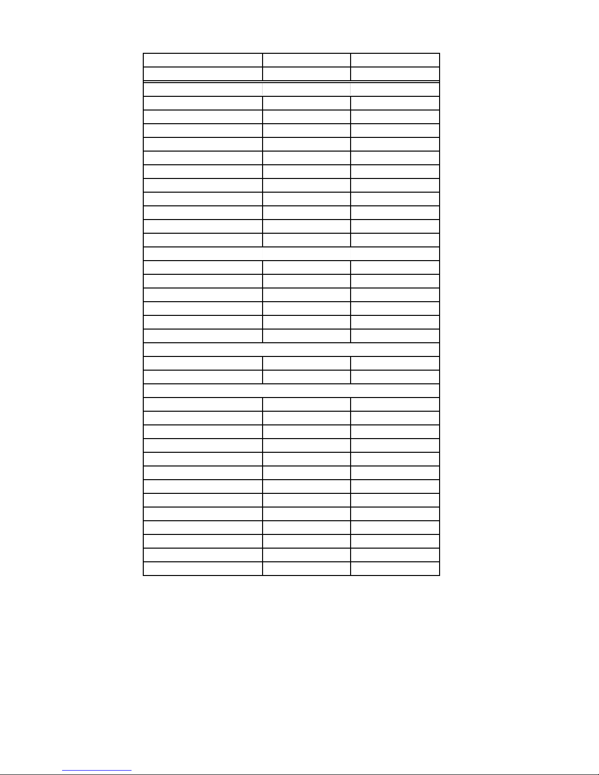
Gas Model Number SF357PEK SF367PEK SF369LEK
Color W / V / Q / T W / V / Q / T Q / T
OVEN FEATURES
Oven Type
Oven Width
Oven Height
Oven Depth
Warm Hold
Broiler Output
Bake Output
Oven Light in Cavity
Auto Oven Light Switch
Manual Oven Light Switch
Self-Clean Self-Clean Self-Clean
24.25" 24.25" 24.25"
17.5" 17.5" 17.5"
19.0" 19.0" 19.0"
No No No
10,000 BTU 10,000 BTU 10,000 BTU
16,500 BTU 16,500 BTU 16,500 BTU
Yes Yes Yes
Yes Yes Yes
Yes-Rocker Yes-Rocker Yes-Rocker
LOWER PANEL/DRAWER
Lower Storage Drawer
Drawer Liner
Drawer Width
Drawer Height
Drawer Depth
Glides
Handle Type
no - panel only Yes Yes
No No Yes
12.7 12.7 12.7
3.0 3.0 3.0
16.3 16.3 16.3
Nylon Rollers Rollers
Drawn Handle Drawn Handle Drawn Handle
LITERATURE
Use & Care Guide
Tech Sheet
Installation Instructions
Service Manual
Yes Yes Yes
Yes Yes Yes
Yes Yes Yes
8178025 8178025 8178025
OTHER SPECIFICATIONS
AGA Approval
Anti-Tip Device Approved
Anti-Tip Shipped w/ Unit
Yes Yes Yes
Floor Brkt/Wall Brkt Floor Brkt/Wall Brkt Floor Brkt/Wall Brkt
Floor Bracket Floor Bracket Floor Bracket
ACCESSORIES
n/a n/a n/a
1-7
Gas Model Number SF379LEK SF387LEK SF389LEK
Color Q / T / B / W / V Q / T / Z / B / W Q / T / Z / B / W
GENERAL INFORMATION
Cleaning System Self-Clean Self-Clean Self-Clean
Burner Type Sealed Sealed Sealed
Oven Window & Size XL window XL window XL window
Broiler Type Waist High Waist High Waist High
Oven Controls EZ200 EZ600 EZ600
Oven Light Yes Yes Yes
Special Features Accubake 1 Accubake 2 Accubake 2
13.5 Power Burner 13.5 Power Burner 13.5 Power Burner
Dual Display Dual Display Dual Display
n/a AccuSimmer AccuSimmer
n/ a Choice bake Choice bake
DIMENSIONS
Height-Overall 46.8" 46.8" 46.8"
Height to Maintop 36" 3 6 " 36 "
Depth 25" 2 5 " 2 5"
Depth to Manifold Panel 25.0" 25.0" 25.0"
Width 29.875" 29.875" 29.875"
Approx Shipping Weight 190 190 190
BACKGUARD FEATURES
Safety Gas Shutoff No No No
Oven Heating Light Indicator in Oven Control in Oven Control in Oven Control
COOKTOP FEATURES
Cooktop Type High UpSwp-Porc High UpSwp-Porc High UpSwp-Porc
Burner Type Sealed Sealed Sealed
Ignition Electronic Electronic Electronic
Burner BTU: Right Front 9,500 BTU 9,500 BTU 9,500 BTU
Burner BTU: Left Front PB - 13,500 BTU PB - 13,500 BTU PB - 13,500 BTU
Burner BTU: Right Rear 5,000 BTU 5,000 BTU 5,000 BTU
Burner BTU: Left Rear 8,000 BTU 8,000 BTU 8,000 BTU
L.P. Convertible(included) Yes-Spud Yes-Spud Yes-Spud
Grate Type Cast Iron Cast Iron Cast Iron
Center Grate No No No
Oven Control Location Center Center Center
Accusimmer Knob No Yes Yes
Power Burner Knob Yes Yes Yes
MAIN CHASSIS FEATURES
Cabinet Painted-text. steel Painted-text. steel Painted-text. steel
Front Frame Porcelain Porcelain Porcelain
Leveling Legs - Plastic Yes-four Yes-four Yes-four
1-8
Gas Model Number SF379LEK SF387LEK SF389LEK
Color Q / T / B / W / V Q / T / Z / B / W Q / T / Z / B / W
OVEN FEATURES
Oven Type Self-Clean Self-Clean Self-Clean
Oven Width 24.25" 24.25" 24.25"
Oven Height 17.5" 17.5" 17.5"
Oven Depth 19.0" 19.0" 19.0"
Warm Hold No Yes Yes
Broiler Output 10,000 BTU 10,000 BTU 10,000 BTU
Bake Output 16,500 BTU 16,500 BTU 16,500 BTU
Oven Light in Cavity Yes Yes Yes
Auto Oven Light Switch Yes Yes Yes
Manual Oven Light Switch Yes-Rocker Yes-Touch Yes-Touch
LOWER PANEL/DRAWER
Lower Storage Drawer Yes Yes Yes
Drawer Liner Yes Yes Yes
Drawer Width 12.7 12.7 12.7
Drawer Height 3.0 3.0 3.0
Drawer Depth 16.3 16.3 16.3
Glides Rollers Rollers Rollers
Warming Drawer No No No
Handle Type Drawn Handle Drawn Handle Drawn Handle
LITERATURE
Use & Care Guide Yes Yes Yes
Tech Sheet Yes Yes Yes
Installation Instructions Yes Yes Yes
Service Manual 8178025 8178025 8178025
OTHER SPECIFICATIONS
AGA Approval Yes Yes Yes
Anti-Tip Device Approved Floor Brkt/Wall Brkt Floor Brkt/Wall Brkt Floor Brkt/Wall Brkt
Anti-Tip Shipped w/ Unit Floor Bracket Floor Bracket Floor Bracket
ACCESSORIES
No No Griddle
1-9
Gas Model Number GS460LEK GS465LEK
Color Q / T / B S
GENERAL INFORMATION
Cleaning System Self-Clean Self-Clean
Burner Type Sealed Sealed
Oven Window & Size XL window XL window
Broiler Type Waist High Waist High
Oven Controls EZ625 EZ625
Oven Light Yes Yes
Special Features Accubake 2 Accubake 2
13.5 Power Burner 13.5 Power Burner
Dual Display Dual Display
AccuSimmer AccuSimmer
Choice bake Choice bake
DIMENSIONS
Height-Overall 46.8" 46.8"
Height to Maintop 36" 3 6 "
Depth 25" 2 5"
Depth to Manifold Panel 25.0" 25.0"
Width 29.875" 29.875"
Approx Shipping Weight 196 196
BACKGUARD FEATURES
Safety Gas Shutoff No No
Oven Heating Light Indicator in Oven Control in Oven Control
COOKTOP FEATURES
Cooktop Type High UpSwp-Porc High UpSwp-Porc
Burner Type Sealed Sealed
Ignition Electronic Electronic
Burner BTU: Right Front 9,500 BTU 9,500 BTU
Burner BTU: Left Front PB - 13,500 BTU PB - 13,500 BTU
Burner BTU: Right Rear 5,000 BTU 5,000 BTU
Burner BTU: Left Rear 8,000 BTU 8,000 BTU
L.P. Convertible(included) Yes-Spud Yes-Spud
Grate Type Cast Iron Cast Iron
Center Grate Yes Yes
Oven Control Location Center Center
Accusimmer Knob Yes Yes
Power Burner Knob Yes Yes
1-10
Gas Model Number GS460LEK GS465LEK
Color Q / T / B S
MAIN CHASSIS FEATURES
Cabinet Painted-text. steel Painted-text. steel
Front Frame Porcelain Porcelain
Leveling Legs - Plastic Yes-four Yes-four
OVEN FEATURES
Oven Type Self-Clean Self-Clean
Oven Width 24.25" 24.25"
Oven Height 17.5" 17.5"
Oven Depth 19.0" 19.0"
Warm Hold Yes Yes
Broiler Output 10,000 BTU 10,000 BTU
Bake Output 16,500 BTU 16,500 BTU
Oven Light in Cavity Yes Yes
Auto Oven Light Switch Yes Yes
Manual Oven Light Switch Yes-Touch Yes-Touch
LOWER PANEL/DRAWER
Lower Storage Drawer Yes Yes
Drawer Liner Yes Yes
Drawer Width 12.7 12.7
Drawer Height 3.0 3.0
Drawer Depth 16.3 16.3
Glides Rollers Rollers
Warming Drawer No No
Handle Type Drawn Handle Drawn Handle
LITERATURE
Use & Care Guide Yes Yes
Tech Sheet Yes Yes
Installation Instructions Yes Yes
Service Manual 8178025 8178025
OTHER SPECIFICATIONS
AGA Approval Yes Yes
Anti-Tip Device Approved Floor Brkt/Wall Brkt Floor Brkt/Wall Brkt
Anti-Tip Shipped w/ Unit Floor Bracket Floor Bracket
ACCESSORIES
n/a n/a
1-11
Gas Model Number GS470LEK GS475LEK
Color Q / T / B S
GENERAL INFORMATION
Cleaning System Self-Clean Self-Clean
Burner Type Sealed Sealed
Oven Window & Size XL window XL window
Broiler Type Waist High Waist High
Oven Controls EZ625 EZ625
Oven Light Yes Yes
Special Features Accubake 2 Accubake 2
13.5 Poawer Burner 13.5 Poawer Burner
Dual Display Dual Display
AccuSimmer AccuSimmer
Choice bake Choice bake
DIMENSIONS
Height-Overall 46.8" 46.8"
Height to Maintop 36" 36 "
Depth 25" 25"
Depth to Manifold Panel 25.0" 25.0"
Width 29.875" 29.875"
Approx Shipping Weight 196 196
BACKGUARD FEATURES
Safety Gas Shutoff No No
Oven Heating Light Indicator in Oven Control in Oven Control
COOKTOP FEATURES
Cooktop Type High UpSwp-Porc High UpSwp-Porc
Burner Type Sealed Sealed
Ignition Electronic Electronic
Burner BTU: Right Front 9,500 BTU 9,500 BTU
Burner BTU: Left Front PB - 13,500 BTU PB - 13,500 BTU
Burner BTU: Right Rear 5,000 BTU 5,000 BTU
Burner BTU: Left Rear 8,000 BTU 8,000 BTU
L.P. Convertible(included) Yes-Spud Yes-Spud
Grate Type Cast Iron Cast Iron
Center Grate Yes Yes
Oven Control Location Center Center
Accusimmer Knob Yes Yes
Power Burner Knob Yes Yes
1-12
Gas Model Number GS470LEK GS475LEK
Color Q / T / B S
MAIN CHASSIS FEATURES
Cabinet Painted-text. steel Painted-text. steel
Front Frame Porcelain Porcelain
Leveling Legs - Plastic Yes-four Yes-four
OVEN FEATURES
Oven Type Self-Clean Self-Clean
Oven Width 24.25" 24.25"
Oven Height 17.5" 17.5"
Oven Depth 19.0" 19.0"
Warm Hold Yes Yes
Broiler Output 10,000 BTU 10,000 BTU
Bake Output 16,500 BTU 16,500 BTU
Oven Light in Cavity Yes Yes
Auto Oven Light Switch Yes Yes
Manual Oven Light Switch Yes-Touch Yes-Touch
LOWER PANEL/DRAWER
Lower Storage Drawer Yes Yes
Drawer Liner Yes Yes
Drawer Width 12.7 12.7
Drawer Height 3.0 3.0
Drawer Depth 16.3 16.3
Glides Warming/AccuRide Warming/AccuRide
Warming Drawer Yes Yes
Handle Type Drawn Handle Drawn Handle
LITERATURE
Use & Care Guide Yes Yes
Tech Sheet Yes Yes
Installation Instructions Yes Yes
Service Manual 8178025 8178025
OTHER SPECIFICATIONS
AGA Approval Yes Yes
Anti-Tip Device Approved Floor Brkt/Wall Brkt Floor Brkt/Wall Brkt
Anti-Tip Shipped w/ Unit Floor Bracket Floor Bracket
ACCESSORIES
n/a n/a
1-13

WHIRLPOOL GAS RANGE WARRANTY
LENGTH OF
WARRANTY:
FULL ONE-YEAR
WARRANTY
FROM DATE OF
PURCHASE.
WHIRLPOOL
WILL PAY FOR:
®
replacement
FSP
parts and repair
labor costs to
correct defects in
materials or workmanship. Service
must be provided
by a Whirlpooldesignated service
company.
WHIRLPOOL
WILL NOT PAY FOR:
A. Service calls to:
1. Correct the installation of the range.
2. Instruct you how to use the range.
3. Replace house fuses or correct house
wiring.
4. Replace owner-accessible light bulbs.
B. Repairs when the range is used in other than
normal, single-family household use.
C. Pickup and delivery. The range is designed to
be repaired in the home.
D. Damage to the range caused by accident, alter-
ation, misuse, abuse, fire, flood, acts of God, or
use of products not approved by Whirlpool.
E. Repairs to parts or systems resulting from unau-
thorized modifications made to the appliance.
F. Replacement parts or repair labor costs for units
operated outside the United States.
WHIRLPOOL CORPORATION SHALL NOT BE LIABLE FOR INCIDENTAL OR CONSEQUENTIAL DAMAGES. Some states do not allow the exclusion or limitation of incidental or conse-
quential damages, so this exclusion or limitation may not apply to you. This warranty gives specific legal rights and you may also have other rights which vary from state to state.
Outside the United States, a different warranty may apply. For details, please contact your
local Whirlpool dealer.
If you need service, first see the “Troubleshooting” section of the Use & Care Guide. After checking “Troublesooting,” additional help can be found by checking the “Requesting Assistance Or
Service” section, or by calling the Whirlpool Consumer Assistance Center telephone number,
1-800-253-1301, from anywhere in the U.S.A.
1-14
INSTALLATION INFORMATION
L.P. GAS CONVERSION
NOTE: Gas conversion from Natural to L.P.
gas must be done by a qualified installer.
WARNING
ELECTRICAL SHOCK HAZARD
Disconnect power before servicing.
Replace all panels before operating.
Failure to do so could result in death or
electrical shock.
FIRE HAZARD
Shut off gas supply line valve.
Make all conversions before turning gas
supply valve back on.
Failure to follow these instructions could
result in explosion, fire, or other injury.
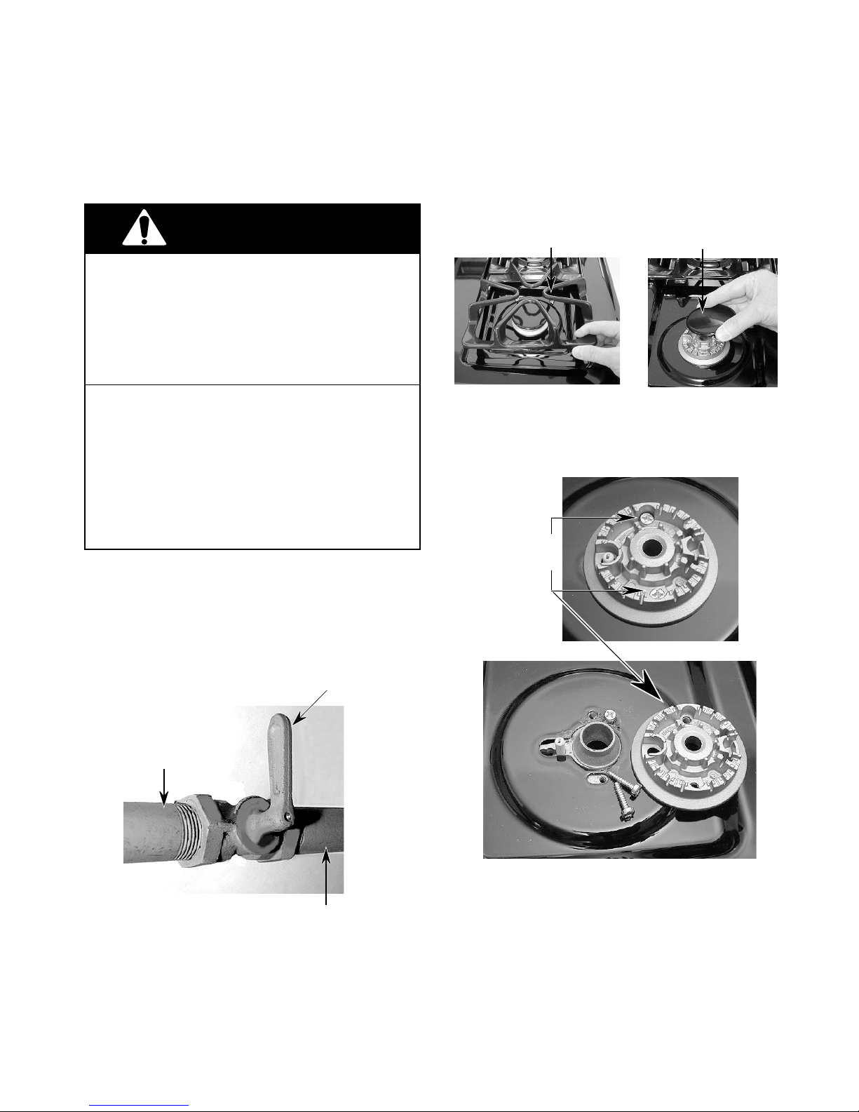
1. Check to make sure that the main gas
supply line to the range has been shut off,
(see below), and that the power supply
cord is disconnected from the AC outlet.
2. To convert the surface burners for use
with L.P. gas:
a)Remove the grates and burner caps.
Grate
b)Remove the two screws from each of
the burner heads and lift the heads off
the cooktop.
Burner Head
& Screws
Burner Cap
Gas Supply To Range
Gas Valve Handle
To “Shutoff” Position
Continued on the next page.
Gas Supply
Line
2-1
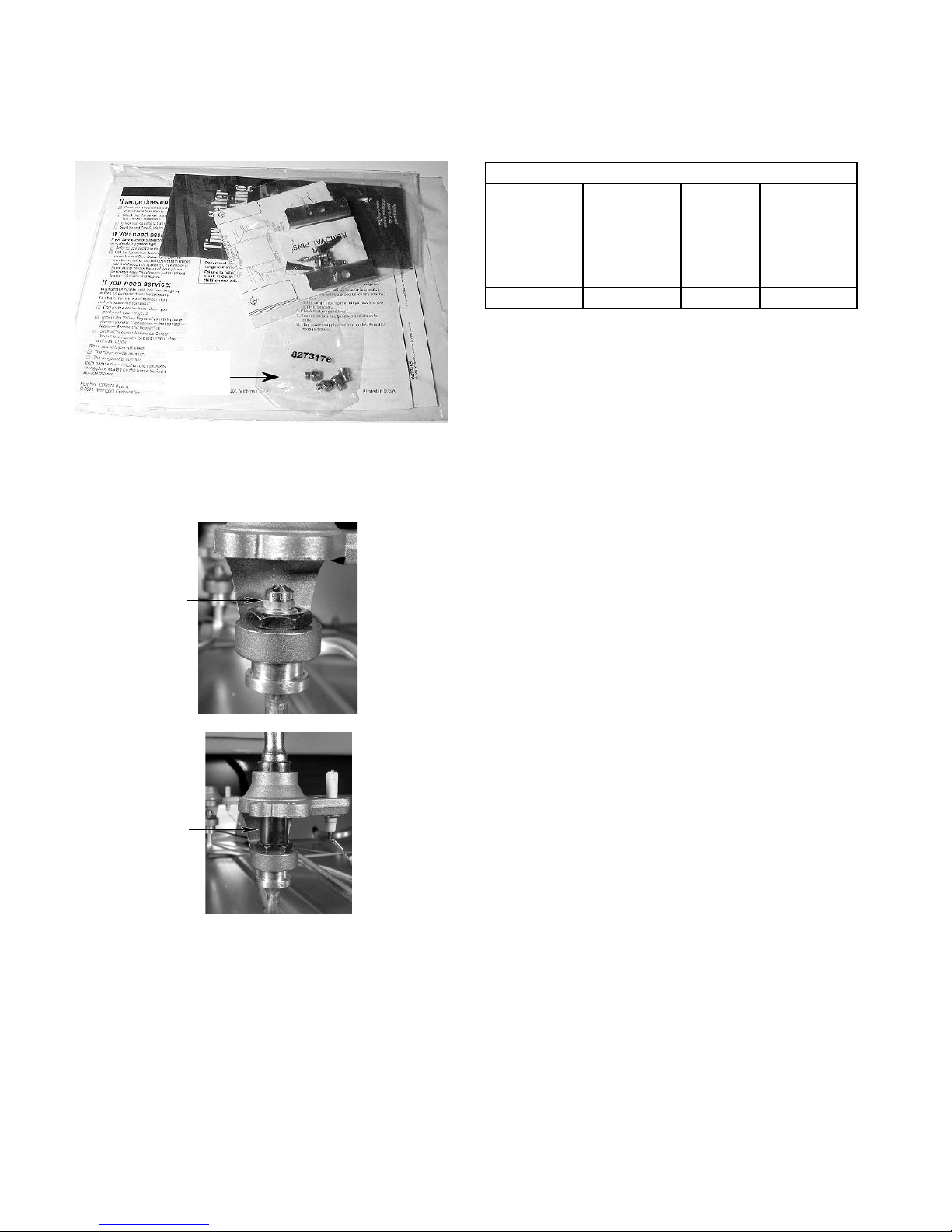
NOTE: The L.P. orifices are contained in a
small plastic bag, which is located inside the
literature bag.
Orifice
Bag
c) Use an 8 mm socket and carefully re-
move the orifice spud from each of the
four burners.
d)Install the four L.P. gas orifices in the
burners, as shown in the following chart
(do not overtighten them):
L.P. GAS
Surface Propane Rate Orifice Color
Burner (B.T.U. /Hr) Number Marking
Left Rear 8,000 L80 Green/Lt. Blue
Left Front 11,000 L 99 Green/Yellow
Right Front 8,000 L80 Green/Lt. Blue
Right Rear 5,000 L65 Green/Brown
e) Place the natural gas orifices in the plas-
tic bag for possible use later.
Surface
Burner
Orifice
8mm
Socket
2-2
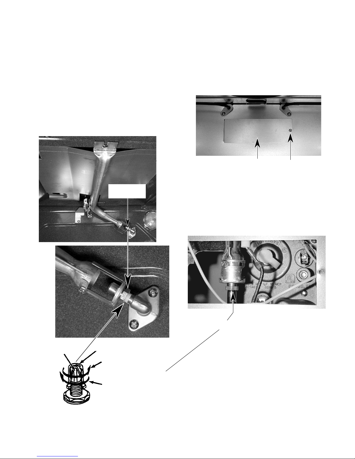
3. To convert the broil burner for use with
L.P. gas:
4. To convert the bake burner for use with
L.P. gas:
a)Open the oven door and remove the
oven racks.
b)Use a 1/2˝ open-end wrench and turn
the orifice hood down snug onto the pin
(approximately 2-1/2 turns). DO NOT
OVERTIGHTEN THE ORIFICE. The
burner flame cannot be properly adjusted if this conversion is not made.
c) Reinstall the oven racks and close the
oven door.
Broil Burner
Orifice
a)Remove the storage/warming drawer
(see page 4-11 for the procedure).
b)Remove the screw from the distribution
valve access cover at the back of the
storage/warming drawer area.
Access Cover Screw
c) Use a 1/2˝ open-end wrench and turn
the bake burner orifice hood down snug
onto the pin (approximately 2-1/2 turns).
DO NOT OVERTIGHTEN THE ORIFICE. The burner flame cannot be properly adjusted if this conversion is not
made.
Pin
Orifice
Hood
Natural Gas:
Increases Flame Size
In This Direction
L.P. Gas:
Increases Flame Size
In This Direction
Bake Burner Orifice Hood
Continued on the next page.
2-3
 Loading...