


KICU265HSS
Whirlpool KICU265HSS, KICU285HSS, KICU265HWT, KICU265HBT, KICU285HWT Technical Education
...
TECHNICAL EDUCATION
36″ & 48″ ISLAND
AND WALL CANOPY
RANGE HOODS
KAC-30
JOB AID 4317332

FORWARD
This Job Aid, KitchenAid “36″ and 48″ Island And Wall Canopy Range Hoods,” (Part No. 4317332),
provides the technician with information on servicing the Island And Wall Canopy Range Hoods.
It is to be used as a training Job Aid and Service Manual. For specific information on the model being
serviced, refer to the “Use and Care Guide” provided with the hood.
The Wiring Diagrams used in this Job Aid are typical and should be used for training purposes only.
Always use the Wiring Diagram supplied with the product when servicing the unit.
GOALS AND OBJECTIVES
The goal of this Job Aid is to provide detailed information that will enable the service technician to
properly diagnose malfunctions and repair the KitchenAid Island And Wall Canopy Range Hoods.
The objectives of this Job Aid are to:
• Understand and follow proper safety precautions.
• Successfully troubleshoot and diagnose malfunctions.
• Successfully perform necessary repairs.
• Successfully return the range hood to its proper operational status.
WHIRLPOOL CORPORATION assumes no responsibility for any repairs made
on our products by anyone other than Authorized Service Technicians.
Copyright © 2001, Whirlpool Corporation, Benton Harbor, MI 49022
- ii -

TABLE OF CONTENTS
Page
GENERAL............................................................................................................................... 1-1
Important Safety Information ............................................................................................. 1-1
KitchenAid Model & Serial Number Designations.............................................................. 1-2
Model & Serial Number Label Location ............................................................................. 1-3
Specifications..................................................................................................................... 1-4
KitchenAid Range Hood Warranty ..................................................................................... 1-7
COMPONENT ACCESS ......................................................................................................... 2-1
Wall Hood Component Locations ...................................................................................... 2-1
Removing A Slide Switch, The Indicator Lamp, & The Blower Motor ................................ 2-2
Removing A Halogen Lamp Socket ................................................................................... 2-5
Island Hood Component Locations.................................................................................... 2-6
Removing The Ballast Transformer ................................................................................... 2-7
Removing The Control Board ............................................................................................ 2-8
Removing The Blower Motor ........................................................................................... 2-10
COMPONENT TESTING ........................................................................................................ 3-1
Blower Motor...................................................................................................................... 3-1
Ballast Transformer ........................................................................................................... 3-1
2- & 3-Position Slide Switches ........................................................................................... 3-2
Speed (Variable) Control ................................................................................................... 3-2
WIRING DIAGRAMS .............................................................................................................. 4-1
Island Hood........................................................................................................................ 4-1
Wall Hood .......................................................................................................................... 4-2
- iii -

— NOTES —
- iv -

GENERAL
WARNING
IMPORTANT SAFETY INFORMATION
Your safety and the safety of others is very important.
Important safety messages have been provided in this Job Aid. Always read and obey all
safety messages.
This is the safety alert symbol.
This symbol alerts you to hazards that can kill or hurt you
and others.
All safety messages will be preceded by the
safety alert symbol and the word “WARNING.”
All safety messages will identify the hazard, tell
you how to reduce the chance of injury, and tell
you what can happen if the instructions are not
followed.
ELECTRICAL SHOCK HAZARD
Disconnect power before servicing.
Replace all panels before operating.
Failure to do so could result in death or
electrical shock.
1-1

KITCHENAID MODEL & SERIAL NUMBER DESIGNATIONS
MODEL NUMBER
MODEL NUMBER K WC U 3 8 0 J S S 0
INTERNATIONAL SALES IND.
OR MARKETING CHANNEL
IF PRESENT
PRODUCT GROUP
K = KITCHENAID BRAND
PRODUCT IDENTIFICATION
IC = ISLAND HOOD
IV = ISLAND VENT
IR = ISLAND RETRACTABLE
WV = WALL VENT
PI = POWER INTERIOR
PE = POWER EXTERIOR
SV = SIDE VENT
WC = WALL CANOPY
MERCHANDISING SCHEME
D = DOWNDRAFT
U = UPDRAFT
CAPACITY / SIZE / SERIES / CONFIGURATION
1ST POSITION 2ND POSITION
0 = SIDE DOWNDRAFT
1 = STANDARD UPDRAFT
2 = SLIDE-OUT UPDRAFT
3 = CANOPY
8 = DOWNDRAFT
0 = 30″ WIDE
5 = 500 CFM
6 = 36″ WIDE
8 = 48″ WIDE
9 = 900 CFM
FEATURES
0 = STANDARD
1 = INTERIOR POWER
2 = EXTERNAL POWER
5 = ELECTRONIC CONTROLS
YEAR OF INTRODUCTION
H = 1999
J = 2000
K = 2001
COLOR CODE
WT = WHITE
BT = BISCUIT
SS = BRUSHED STAINLESS STEEL
ENGINEERING CHANGE (0, 1, 2, ETC.)
SERIAL NUMBER
SERIAL NUMBER F J J 4 6 02453
MANUFACTURING SITE
YEAR OF PRODUCTION
J = 1999, K = 2000, L = 2001, M = 2002
WEEK OF PRODUCTION
46TH WEEK
PRODUCT SEQUENCE NUMBER
1-2
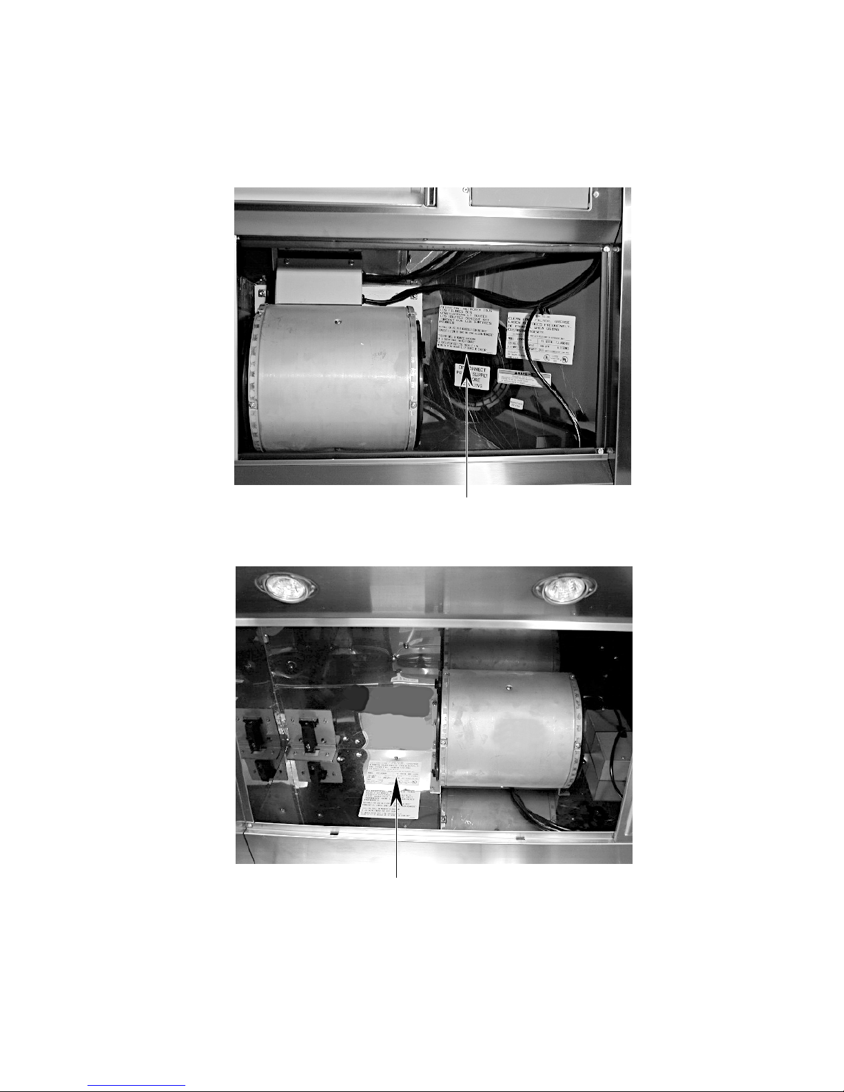
MODEL & SERIAL NUMBER LABEL LOCATION
The Model/Serial Number label locations are shown below.
Model & Serial Number Location
(Island Range Hood)
Model & Serial Number Location
(Wall Range Hood)
1-3
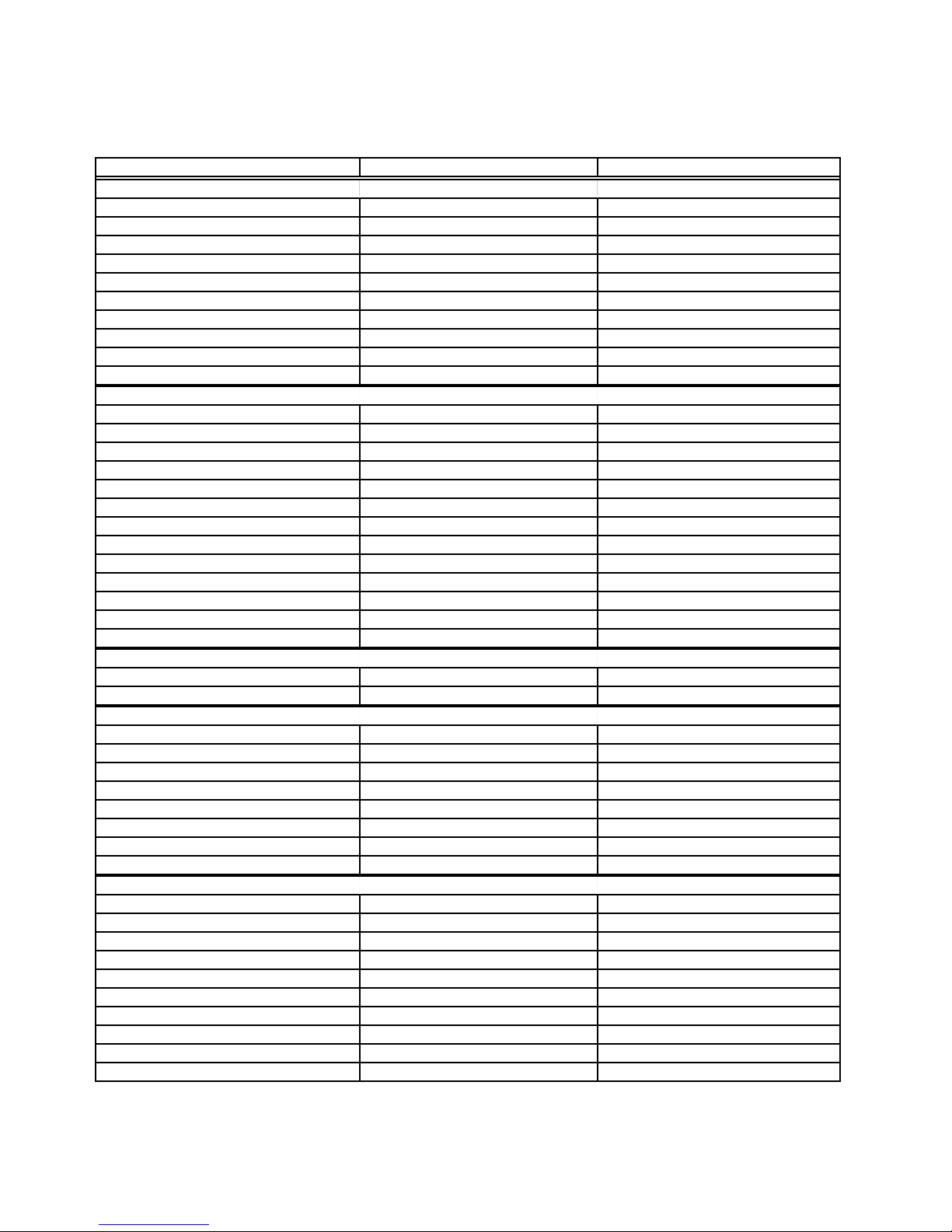
SPECIFICATIONS
Island Hoods
Model Number
Dimensions/Specifications
Overall Width (in) 35 3/8" 47 1/4"
Overall Depth (in) 23 5/8" 23 5/8"
Canopy Height (in) 10 1/4" 10 1/4"
Chimney Height (in) 24 5/8" to 34 3/4" 24 5/8" to 34 3/4"
Weight
Net Weight (lbs) 77 8 4
Shipping Weight (lbs) 82 90
Ratings
120v AC Yes Yes
Circuit Amps
Exterior
Hood Exterior
Type/Configuration Canopy-Updraft Canopy-Updraft
Size (Inches) 36 Inches 48 Inches
Color Stainless Stainless
Grease Filters 3 Heavy Duty (DW Safe) 3 Heavy Duty (DW Safe)
CFM 600 600
Sones 6. 5 6. 5
Light 2 Fluorescent Bulbs 2 Fluorescent Bulbs
Brand Logo Location KitchenAid KitchenAid
Controls
On/Off Yes Yes
Variable Speed Yes Yes
Auto Off
Interior
Ducting Convertible with kit Convertible with kit
Dimension
Accessories
Backsplash
Backsplash Kit Part/Description
Ductless Operation Kit Part/Description 4378625/Stainless 4378625/Stainless
Chimney Extension Kit
Wire Rack Kit Part/Description
Wire Rack Hanger Kit Part/Description
Utensil Bar-15 Inch Sides Kit 4378619 4378619
Utensil Bar-Back
Miscellaneous
Product Literature
Installation Instructions Part/Comment 4360369 4360369
Job Aid Part/Comment 4317332 4317332
Use & Care Guide Part/Comment 4360369/English; 4360370/French 4360369/English; 4360370/French
Wiring Diagram Part/Comment In Use and Care Guide In Use and Care Guide
Other
Agency Approvals UL,CUL UL,CUL
Warranty
Full (Months) 12 12
Power System Motor 48 Mo 48 Mo
KICU265H SS, WT, BT KICU285H SS, WT, BT
15 AMP 15 AMP
No No
3 1/4" x 10" 3 1/4" x 10"
1-4
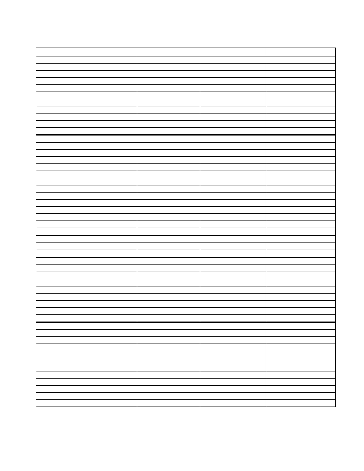
Wall Hoods
Model Number
Dimensions/Specifications
Overall Width (in) 29 7/8" 35 3/8" 47 1/4"
Overall Depth (in) 19 1/4" 19 1/4" 19 1/4"
Canopy Height (in) 9 1/2" 9 1/2" 9 1/2"
Chimney Height (in) 23" to 42" 23" to 42" 23" to 42"
Weight
Net Weight (lbs) 4 5 52 59
Shipping Weight (lbs) 4 9 5 7 6 5
Ratings
120v AC Yes Yes Yes
Circuit Amps
Exterior
Hood Exterior
Type/Configuration Wall-Updraft Wall-Updraft Wall-Updraft
Size (Inches) 30 Inches 36 Inches 48 Inches
Color Stainless Stainless Stainless
Grease Filters 2 Heavy Duty (DW Safe) 3 Heavy Duty (DW Safe) 3 Heavy Duty (DW Safe)
CFM 600 600 600
Sones 6. 5 6. 5 6. 5
Light 1 Fluorescent Bulb 1 Fluorescent Bulb 1 Fluorescent Bulb
Brand Logo Location KitchenAid KitchenAid KitchenAid
Controls
On/Off Yes Yes Yes
Variable Speed Yes Yes Yes
Auto Off
Interior
Ducting Convertible with kit Convertible with kit Convertible with kit
Dimension
Accessories
Backsplash
Backsplash Kit Part/Description 8171295/Stainless 4378615/Stainless 8171296/Stainless
Ductless Operation Kit Part/Description 4378621/Stainless 4378621/Stainless 4378621/Stainless
Chimney Extension Kit N / A N / A N / A
Wire Rack Kit Part/Description 8171297 4378616 8171298
Wire Rack Hanger Kit Part/Description 4378617 4378617 4378617
Utensil Bar-15 Inch Sides Kit 4378619 4378619 4378619
Utensil Bar-Back
Miscellaneous
Product Literature
Installation Instructions Part/Comment
Job Aid Part/Comment 4317332 4317332 4317332
Use & Care Guide Part/Comment
Wiring Diagram Part/Comment In Use & Care Guide In Use & Care Guide In Use & Care Guide
Other
Agency Approvals UL,CUL UL,CUL UL,CUL
Warranty
Full (Months) 12 12 12
Power System Motor 48 Mo 48 Mo 48 Mo
KWCU205H SS, WT, BT KWCU265H SS, WT, BT KWCU285H SS, WT, BT
15 AMP 15 AMP 15 AMP
No No No
3 1/4" x 10" 3 1/4" x 10" 3 1/4" x 10"
8171299 4378618
4360367/English;
4360368/French
4360367/English;
4360368/French
4360367/English;
4360368/French
1-5
 Loading...