


HE2t - 3.7 cu. Ft. Front Load Washer
Whirlpool HE2t - 3.7 cu. Ft. Front Load Washer, duet sport WFW8300SW, duet sport WFW8500SW, duet sport WFW8500SR User Manual
CONSUMER SERVICES TECHNICAL
EDUCATION GROUP PRESENTS
L-78
JOB AID
Part No. 8178558
FRONT-LOADING
AUTOMATIC
WASHER
MODELS: WFW8300SW, WFW8500SW, WFW8500SR

FORWARD
This Whirlpool Job Aid, “Duet Sport™ Front-Loading Automatic Washer” (Part No. 8178558),
provides the technician with information on the installation, operation, and service of the Duet
Sport™ Front-Loading Automatic Washer. For specific information on the model being serviced,
refer to the “Use and Care Guide,” or “Tech Sheet” provided with the washer.
The Wiring Diagram used in this Job Aid is typical and should be used for training purposes only.
Always use the Wiring Diagram supplied with the product when servicing the unit.
GOALS AND OBJECTIVES
The goal of this Job Aid is to provide information that will enable the service technician to properly diagnose malfunctions and repair the Duet Sport™ Front-Loading Automatic Washer.
The objectives of this Job Aid are to:
Understand and follow proper safety precautions.
•
Successfully troubleshoot and diagnose malfunctions.
•
Successfully perform necessary repairs.
•
Successfully return the washer to its proper operational status.
•
WHIRLPOOL CORPORATION assumes no responsibility for any repairs
made on our products by anyone other than Authorized Service Technicians.
Copyright © 2006, Whirlpool Corporation, Benton Harbor, MI 49022
- ii -

TABLE OF CONTENTS
Page
GENERAL . . . . . . . . . . . . . . . . . . . . . . . . . . . . . . . . . . . . . . . . . . . . . . . . . . . . . . . . . . . . . . 1-1
Washer Safety . . . . . . . . . . . . . . . . . . . . . . . . . . . . . . . . . . . . . . . . . . . . . . . . . . . . . . . . . .
Model & Serial Number Designations . . . . . . . . . . . . . . . . . . . . . . . . . . . . . . . . . . . . . . . . 1-2
Model & Serial Number Label And Tech Sheet Locations . . . . . . . . . . . . . . . . . . . . . . . . .
Specifications . . . . . . . . . . . . . . . . . . . . . . . . . . . . . . . . . . . . . . . . . . . . . . . . . . . . . . . . . . 1-4
1-1
1-3
INSTALLATION INFORMATION
Installation Requirements . . . . . . . . . . . . . . . . . . . . . . . . . . . . . . . . . . . . . . . . . . . . . . . . . 2-1
Installation Instructions . . . . . . . . . . . . . . . . . . . . . . . . . . . . . . . . . . . . . . . . . . . . . . . . . . . 2-6
PRODUCT OPERATION . . . . . . . . . . . . . . . . . . . . . . . . . . . . . . . . . . . . . . . . . . . . . . . . . . . .
Features And Benefits . . . . . . . . . . . . . . . . . . . . . . . . . . . . . . . . . . . . . . . . . . . . . . . . . . . . 3-1
Washer Use . . . . . . . . . . . . . . . . . . . . . . . . . . . . . . . . . . . . . . . . . . . . . . . . . . . . . . . . . . . .
Washer Care . . . . . . . . . . . . . . . . . . . . . . . . . . . . . . . . . . . . . . . . . . . . . . . . . . . . . . . . . .
Troubleshooting . . . . . . . . . . . . . . . . . . . . . . . . . . . . . . . . . . . . . . . . . . . . . . . . . . . . . . . .
COMPONENT ACCESS
Component Locations . . . . . . . . . . . . . . . . . . . . . . . . . . . . . . . . . . . . . . . . . . . . . . . . . . . . 4-1
Removing The Console And The Touchpad/LED Assembly
Removing The Central Control Unit . . . . . . . . . . . . . . . . . . . . . . . . . . . . . . . . . . . . . . . . . .
Removing The Water Inlet Valve . . . . . . . . . . . . . . . . . . . . . . . . . . . . . . . . . . . . . . . . . . . .
Removing The Pressure Switch
Removing The Line Filter & Power Supply Cord . . . . . . . . . . . . . . . . . . . . . . . . . . . . . . . .
Removing The Detergent Dispenser Assembly . . . . . . . . . . . . . . . . . . . . . . . . . . . . . . . .
Removing The
Removing The Door Switch Assembly And The Bellows . . . . . . . . . . . . . . . . . . . . . . . . .
Removing The Drain Pump . . . . . . . . . . . . . . . . . . . . . . . . . . . . . . . . . . . . . . . . . . . . . . .
Removing The ECO Valve . . . . . . . . . . . . . . . . . . . . . . . . . . . . . . . . . . . . . . . . . . . . . . . .
Removing The Motor Control Unit . . . . . . . . . . . . . . . . . . . . . . . . . . . . . . . . . . . . . . . . . .
Removing The Temperature Sensor & Heater
Removing The Drive Belt And Motor . . . . . . . . . . . . . . . . . . . . . . . . . . . . . . . . . . . . . . . .
Removing An Interlock Switch . . . . . . . . . . . . . . . . . . . . . . . . . . . . . . . . . . . . . . . . . . . . .
Removing The Basket Drive Pulley . . . . . . . . . . . . . . . . . . . . . . . . . . . . . . . . . . . . . . . . .
Removing The Tub & Basket And Baffle . . . . . . . . . . . . . . . . . . . . . . . . . . . . . . . . . . . . .
Detergent Dispenser Motor . . . . . . . . . . . . . . . . . . . . . . . . . . . . . . . . . . . 4-13
. . . . . . . . . . . . . . . . . . . . . . . . . . . . . . . . . . . . . . . . . . . . . . . . . . 4-1
. . . . . . . . . . . . . . . . . . . . . . . . . . . . . . . . . . . . . . . . . . . . . 2-1
3-1
3-3
3-12
3-15
. . . . . . . . . . . . . . . . . . . . . . . 4-2
4-4
4-6
. . . . . . . . . . . . . . . . . . . . . . . . . . . . . . . . . . . . . . . . . . . . 4-7
4-8
4-10
4-14
4-17
4-19
4-20
. . . . . . . . . . . . . . . . . . . . . . . . . . . . . . . . 4-22
4-23
4-25
4-27
4-28
COMPONENT TESTING . . . . . . . . . . . . . . . . . . . . . . . . . . . . . . . . . . . . . . . . . . . . . . . . . . . 5-1
Inlet Valve Solenoids . . . . . . . . . . . . . . . . . . . . . . . . . . . . . . . . . . . . . . . . . . . . . . . . . . . . .
Pressure Switch . . . . . . . . . . . . . . . . . . . . . . . . . . . . . . . . . . . . . . . . . . . . . . . . . . . . . . . . 5-2
Line Filter . . . . . . . . . . . . . . . . . . . . . . . . . . . . . . . . . . . . . . . . . . . . . . . . . . . . . . . . . . . . . . 5-3
Detergent Dispenser Motor & Switch . . . . . . . . . . . . . . . . . . . . . . . . . . . . . . . . . . . . . . . . 5-4
Door Switch . . . . . . . . . . . . . . . . . . . . . . . . . . . . . . . . . . . . . . . . . . . . . . . . . . . . . . . . . . . . 5-5
Drain Pump . . . . . . . . . . . . . . . . . . . . . . . . . . . . . . . . . . . . . . . . . . . . . . . . . . . . . . . . . . . . 5-6
Temperature Sensor & Heater . . . . . . . . . . . . . . . . . . . . . . . . . . . . . . . . . . . . . . . . . . . . . .
Drive Motor . . . . . . . . . . . . . . . . . . . . . . . . . . . . . . . . . . . . . . . . . . . . . . . . . . . . . . . . . . . . 5-8
Interlock Switch . . . . . . . . . . . . . . . . . . . . . . . . . . . . . . . . . . . . . . . . . . . . . . . . . . . . . . . . . 5-8
5-1
5-7
- iii -

Page
DIAGNOSTICS & TROUBLESHOOTING . . . . . . . . . . . . . . . . . . . . . . . . . . . . . . . . . . . . . . 6-1
Diagnostics . . . . . . . . . . . . . . . . . . . . . . . . . . . . . . . . . . . . . . . . . . . . . . . . . . . . . . . . . . . . 6-1
Diagnostic Guide . . . . . . . . . . . . . . . . . . . . . . . . . . . . . . . . . . . . . . . . . . . . . . . . . . . . . . 6-1
Failure/Error Display Codes . . . . . . . . . . . . . . . . . . . . . . . . . . . . . . . . . . . . . . . . . . . . . 6-2
Diagnostic Test
. . . . . . . . . . . . . . . . . . . . . . . . . . . . . . . . . . . . . . . . . . . . . . . . . . . . . . . 6-5
Error History Display . . . . . . . . . . . . . . . . . . . . . . . . . . . . . . . . . . . . . . . . . . . . . . . . . . . 6-6
History Overview Test Program . . . . . . . . . . . . . . . . . . . . . . . . . . . . . . . . . . . . . . . . . . .
Manual Diagnostic Test . . . . . . . . . . . . . . . . . . . . . . . . . . . . . . . . . . . . . . . . . . . . . . . . .
Manual Overview Test Program
. . . . . . . . . . . . . . . . . . . . . . . . . . . . . . . . . . . . . . . . . . 6-7
Electronic Assemblies - Removal Or Replacement . . . . . . . . . . . . . . . . . . . . . . . . . . . .
Washer Care . . . . . . . . . . . . . . . . . . . . . . . . . . . . . . . . . . . . . . . . . . . . . . . . . . . . . . . . .
Troubleshooting Guide
. . . . . . . . . . . . . . . . . . . . . . . . . . . . . . . . . . . . . . . . . . . . . . . . . . .6-11
6-6
6-7
6-8
6-9
WIRING DIAGRAMS . . . . . . . . . . . . . . . . . . . . . . . . . . . . . . . . . . . . . . . . . . . . . . . . . . . . . . . 7-1
Washer
. . . . . . . . . . . . . . . . . . . . . . . . . . . . . . . . . . . . . . . . . . . . . . . . . . . . . . . . . . . . . . . 7-1
Grounding System . . . . . . . . . . . . . . . . . . . . . . . . . . . . . . . . . . . . . . . . . . . . . . . . . . . . . . . 7-2
- iv -

GENERAL
DANGER
WASHER SAFETY
Your safety and the safety of others is very important.
We have provided many important safety messages in this Job Aid and on the appliance.
Always read and obey all safety messages.
This is the safety alert symbol.
This symbol alerts you to potential hazards that can kill or hurt you and
others.
All safety messages will follow the safety alert symbol and either the word
“DANGER” or “WARNING.” These words mean:
You can be killed or seriously injured if you don’t
immediately follow instructions.
You can be killed or seriously injured if you don’t
follow instructions.
All safety messages will tell you what the potential hazard is, tell you how to reduce the
chance of injury, and tell you what can happen if the instructions are not followed.
1-1

MODEL & SERIAL NUMBER DESIGNATIONS
MODEL NUMBER
MODEL NUMBER W F W 8 3 00 S W 0
BRAND
W = Whirlpool
ACCESS
F = Front Loading
PRODUCT
W = Washer
SERIES
5 = Whirlpool Leap 6 = Oasis
7 = 24
9 = Duet Front Load
PRICE POINT LEVELS (1 - 9)
TRADE PARTNER ID (00 = BRANDED)
YEAR OF INTRODUCTION
S = 2006, T = 2007
COLOR CODE
T = Biscuit
Q = White
W = White With Metallic Accent
R = White With Metallic (Sport Only)
ENGINEERING CHANGE (NUMERIC)
˝ Front Load 8 = Mid Line Front Load
SERIAL NUMBER
SERIAL NUMBER HL T 35 10901
DIVISION RESPONSIBILITY
Horizontal Washer Facility,
Monterrey, MX
YEAR OF PRODUCTION
T = 2006
WEEK OF PRODUCTION
35 = 35th Week
PRODUCT SEQUENCE NUMBER
1-2
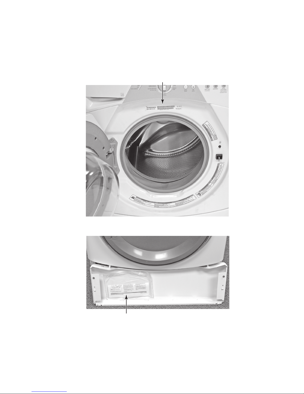
MODEL & SERIAL NUMBER LABEL
AND TECH SHEET LOCATIONS
The Model & Serial Number Label and Tech Sheet locations are shown below.
Model & Serial Number Label
Tech Sheet (Behind Lower Access Panel)
1-3

SPECIFICATIONS
Model Number WFW8300SW WFW8500SW WFW8500SR
Model Description Front Load Washer Front Load Washer Front Load Washer
Color White with
Gray Accents
Capacity (Cu.Ft. IEC) 3.3 3.6 3.6
Temperature Control ATC - 2 ATC - 4 ATC - 4
Heater No Yes Yes
Sensors Suds Sensor,
NTC (Thermistor),
Water Level Sensor
Tumble Speed Heavy Duty &
Normal = 40/35 RPM
Gentle = 31 RPM
Spin Speed High = 1050 RPM
Medium = 800 RPM
Low = 600 RPM
Motor Variable Speed; 1/4 HP Variable Speed; 1/4 HP Variable Speed; 1/4 HP
Voltage
Frequency 60 Hz 60 Hz 60 Hz
Amps 10 Amp 10 Amp 10 Amp
Water Consumption Average
DOE (Gallons-Per-Cycle)
Rated Load 15.43 lbs. (7 kg) 17.64 lbs. (8 kg) 17.64 lbs. (8 kg)
Load Pounds Maximum = 11.7
Height 36.0" 36.0" 36.0"
Install Depth: Min - Max 29.25" 30.00" 30.00"
Width
Product Weight (approx)
120V 120V 120V
12.77 14.1 14.1
Average = 7.35
Minimum = 3
27" 27" 27"
242 lbs. 242 lbs. 242 lbs.
White with
Gray Accents
Suds Sensor,
NTC (Thermistor),
Water Level Sensor
Heavy Duty &
Normal = 40/35 RPM
Gentle = 31 RPM
High = 1100 RPM
Medium = 800 RPM
Low = 600 RPM
N/A
White with Sterling
Bright Accents
Suds Sensor,
NTC (Thermistor),
Water Level Sensor
Heavy Duty &
Normal = 40/35 RPM
Gentle = 31 RPM
High = 1100 RPM
Medium = 800 RPM
Low = 600 RPM
N/A
1-4
INSTALLATION INFORMATION
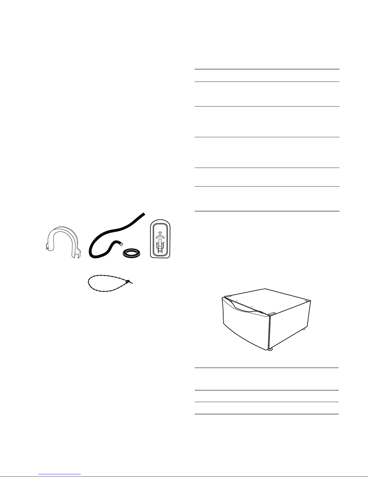
A. U-shaped hose form
B. Water inlet hoses (2
)
C. Inlet hose washers (4)
D. Transit bolt hole plug
E. Beaded tie stra
p
A B C
D
E
Optional pedestal
If You Have You Will Need to Buy
Laundry tub or
standpipe taller
than 96" (2.4 m)
Sump pump system (if not already
available)
Overhead sewer Standard 20 gal. (76 L), 30" (76.2 cm)
tall drain tub or utility sink and sump
pump (available from local plumbing
suppliers)
Floor drain Siphon break, Part Number 285834;
additional drain hose
Part Number 8318155; an
d connector
kit, Part
Number 2858835
Drain hose too
short
4 ft (1.2 m) drain hose extension kit,
Part Number 285886
3
Water faucets
beyond re
ach of
fill hoses
2 longer water fill hoses:
6 ft (1.8 m)
Part Number 76314
10 ft (3.0 m) Part Number 350008
Pedestal
Height
Approximate
Height with
Washer
Color Model
Number
10" (25.4 cm) 46" (116.8 cm) White WHP1000SQ
15.5" (39.4 cm) 51.5" (130.8 cm) White WHP1500S
Q
INSTALLATION REQUIREMENTS
TOOLS AND PARTS
Gather the required tools and parts before
starting installation. The parts supplied are in
the washer drum.
Tools needed for connecting the water inlet hoses
Pliers (that open to 1-9/16˝ [39.5 mm])
•
Flashlight (optional)
•
Tools needed for installation
Open end wrenches 17 mm and 13 mm
•
Level
•
Wood block
•
Ruler or measuring tape
•
Parts supplied
Alternate Parts
Your installation may require additional parts.
If you are interested in purchasing one of the
items listed here, call the toll-free number on
the cover or in the “Assistance or Service”
section in the “Use & Care Guide.”
OPTIONS
Pedestal
You have the option of purchasing pedestals
of different heights separately for this washer.
You may select a 10
(39.4 cm) pedestal. Remember that the ped
estal will add to the total height of the unit.
˝ (25.4 cm) or a 15.5˝
-
2-1
Stack Kit
50
¹⁄
4
"
(127.6 cm)
27"
(68.6 cm)
36"
(91.4 cm)
29¹⁄4"
(74.3 cm)
1"
(2.5 cm)
1"
(2.5 cm)
36" min.
(91.4 cm)
27"
(68.6 cm)
2" (5 cm)
Are you planning to stack your washer and
dryer? To do so you will need to purchase a
Stack Kit.
To order, call the dealer from whom you pur
chased your dryer or refer to the “Assistance
or Service” section in the “Use & Care Guide.”
Ask for Part Number 8572546.
LOCATION REQUIREMENTS
Selecting the proper location for your washer
improves performance and minimizes noise
and possible washer “walk.”
The washer can be installed under a custom
counter, or in a basement, laundry room, clos
et, or recessed area. See “Drain System.”
Companion appliance location requirements
should also be considered. Proper installation
is your responsibility.
You will need
Installation Clearances
The location must be large enough to allow
•
the washer door to be fully opened.
Additional spacing should be considered
•
-
for ease of installation and servicing. The
door opens more than 90°, and it is not re
versible.
Additional clearances might be required for
•
wall, door, and floor moldings.
Additional spacing of 1
•
sides of the washer is recommended to re
duce noise transfer.
Companion appliance spacing should also
•
be considered.
-
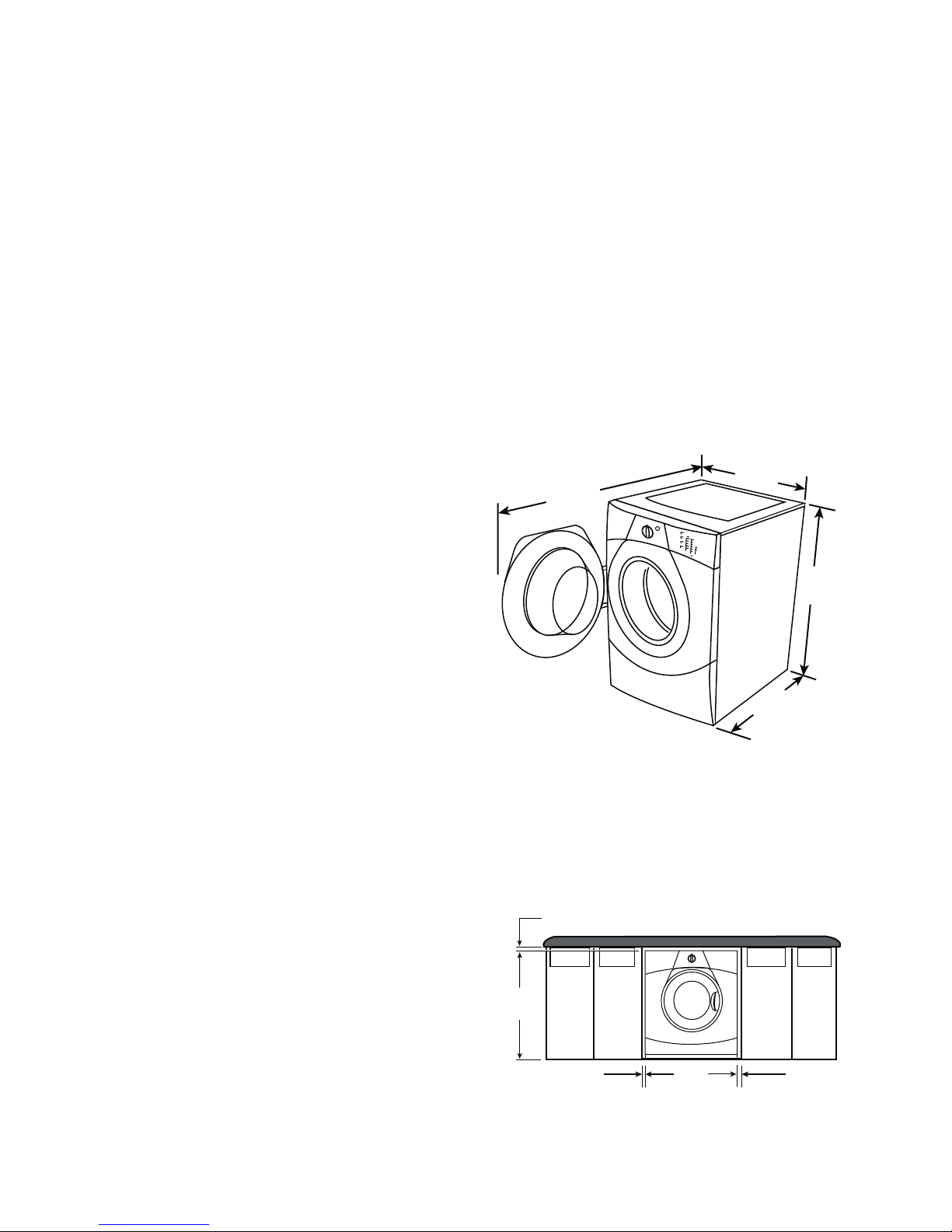
Washer Dimensions
-
˝ (2.5 cm) on all
-
A water heater set to deliver 120
•
°F (49°C)
water to the washer.
A grounded electrical outlet located with-
•
in 6 ft (1.8 m) of where the power cord is
attached to the back of the washer. See
“Electrical Requirements.”
Hot and cold water faucets located within
•
4 ft (1.2 m) of the hot and cold water fill
valves, and water pressure of 20-100 psi
(137.9-689.6 kPa).
A level floor with a maximum slope of
•
1˝(2.5 cm) under entire washer. Installing
the washer on soft floor surfaces, such as
carpets or surfaces with foam backing, is
not recommended.
A sturdy and solid floor to support the
•
washer with a total weight (water and load)
of 400 lbs (180 kg).
Do not operate your washer in temperatures
below 32
°F (0°C). Some water can remain
in the washer and can cause damage in low
temperatures.
Recommended installation spacing for
custom undercounter installation
The dimensions shown are for the recommended spacing.
Custom undercounter installation Washer only
2-2
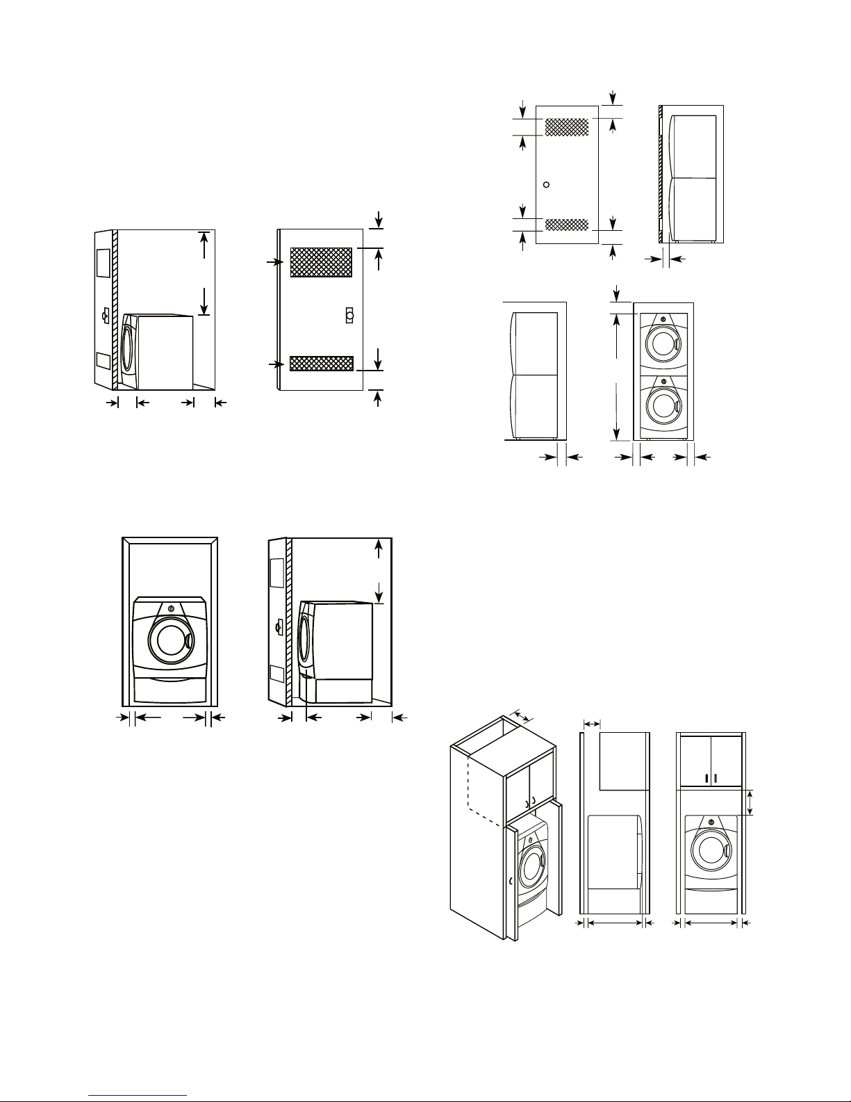
A. Side view - closet or confined area
B. Closet door
with vents
48"
(122 cm)
A
B
3"
(7.6 cm)
3"
(7.6 cm)
1"
(2.5 cm)
4"
(10.2 cm)
29¹⁄4"
(80 cm)
48 in.
2
(310 cm2)
24 in.
2
(155 cm2)
A. Recessed area
B. Side view - closet or confined area
1"
(2.5 cm)
29
¹⁄
4
"
(80 cm)
1"
(2.5 cm)
1"
(2.5 cm)
27"
(68.6 cm)
4"
(10.2 cm)
38" min.
(96.5 cm)
A B
Recommended installation spacing for re-
*Min. top and bottom air openings for closet door.
**External exhaust elbow requires additional space.
***Wall, door and floor molding may require additional spacing.
48 in2 *
(310 cm2)
3" (7.6 cm)
12" (30.5 cm)
72"
(182.9 cm)
27"
(68.6 cm)
3" (7.6 cm)
1" (2.5 cm)
5 ¹⁄4"**
(13.3 cm)
1"***
(2.5 cm)
1"***
(2.5 cm)
(155 cm2)
24 in2 *
7" (17.8 cm)
9"
(22.9 cm)
7" (17.8 cm)
4"
(10.2 cm)
31
¹⁄2
"
(80.0 cm)
27"
(68.6 cm)
1"
(2.5 cm)1"(2.5 cm)
1"
(2.5 cm)
cessed or closet installation, with or with
out a pedestal
The dimensions shown are for the recommended spacing.
Recessed area or closet installation
-
Recessed or closet installation Washer on pedestal
Recommended installation spacing for recessed or closet installation, with stacked
washer and dryer
The dimensions shown, at the top of the right
column, are for the recommended spacing.
Recommended installation spacing for
cabinet installation
The dimensions shown are for the recommended spacing.
For cabinet installation with a door, the
minimum ventilation openings in the top
are required.
2-3
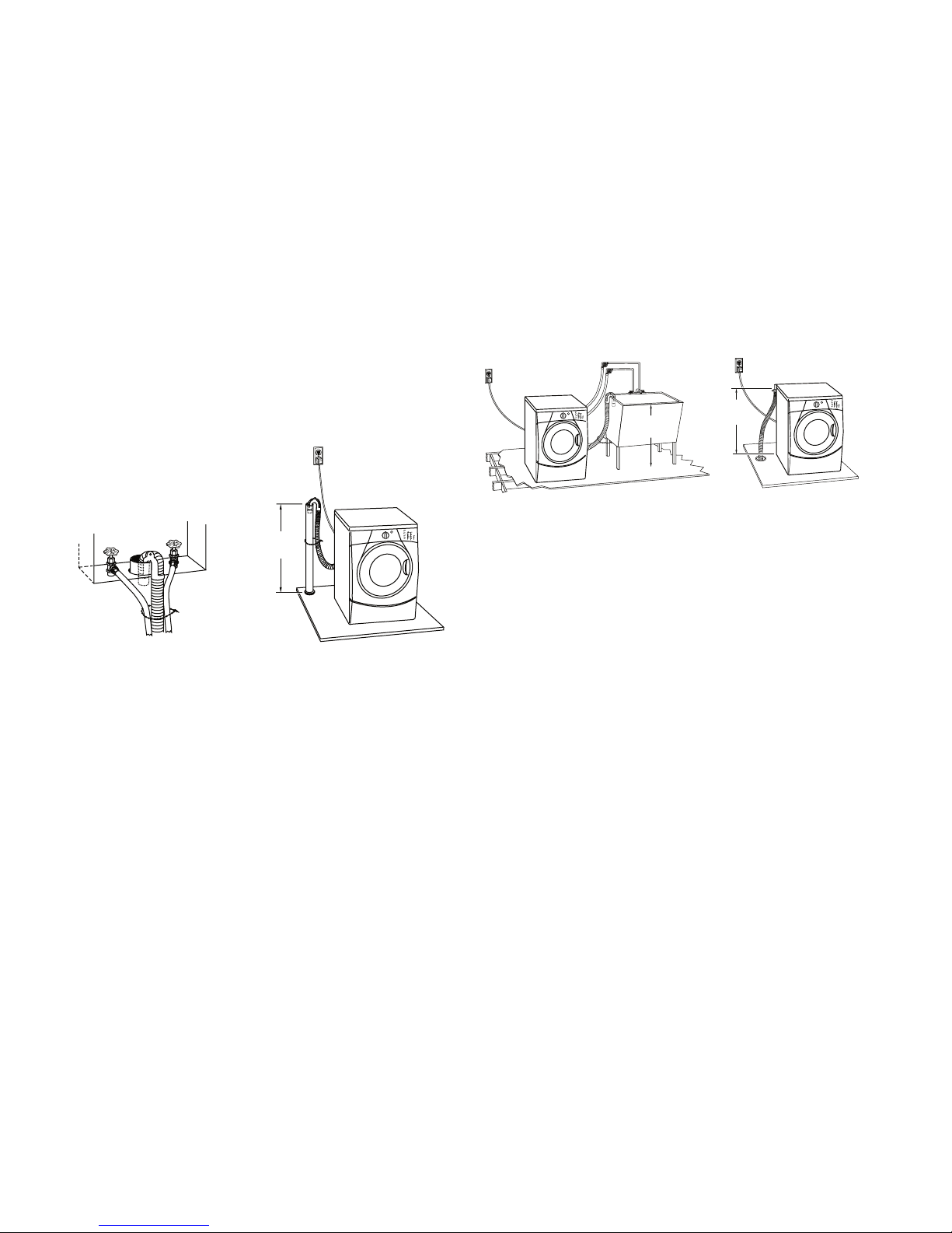
DRAIN SYSTEM
30" min.
(76.2 cm)
A
B
A B
30" min.
(76.2 cm)
26" min.
(66 cm)
The washer can be installed using the standpipe drain system (floor or wall), the laundry
tub drain system, or the floor drain system.
Select the drain hose installation method you
need. See “Tools and Parts.”
Standpipe drain system - wall or floor
(views A & B)
The standpipe drain requires a minimum
diameter standpipe of 2˝ (5 cm). The minimum carry-away capacity can be no less than
17 gal. (64 L) per minute.
The top of the standpipe must be at least 30˝
(76.2 cm) high and no higher than 96
from the bottom of the washer.
˝ (2.4 m)
Laundry tub drain system (view A)
The laundry tub needs a minimum 20 gal.
(76 L) capacity. The top of the laundry tub must
be at least 30˝ (76.2 cm) above the floor.
Floor drain system (view B)
The floor drain system requires a siphon break
that may be purchased separately. See “Tools
and Parts.”
The siphon break must be a minimum of 28˝
(71 cm) from the bottom of the washer. Addi
tional hoses might be needed.
-
2-4

ELECTRICAL REQUIREMENTS
Electrical Shock Hazard
Plug into a grounded 3 prong outlet.
Do not remove ground prong.
Do not use an adapter.
Do not use an extension cord.
Failure to follow these instructions can
result in death, fire, or electrical shock.
•
A 120 volt, 60 Hz., AC only, 15- or 20amp, fused electrical supply is required. A
time-delay fuse or circuit breaker is recommended. It is recommended that a sepa
rate circuit serving only this appliance be
provided.
This washer is equipped with a power sup-
•
ply cord having a 3 prong grounding plug.
To minimize possible shock hazard, the
•
cord must be plugged into a mating,
3 prong, grounding-type outlet, grounded
in accordance with local codes and ordinances. If a mating outlet is not available,
it is the personal responsibility and obli
gation of the customer to have the prop
erly grounded outlet installed by a qualified
electrician.
GROUNDING INSTRUCTIONS
For a grounded, cord-connected washer:
This washer must be grounded. In the
event of a malfunction or breakdown,
grounding will reduce the risk of electrical
shock by providing a path of least resistance for electric current. This washer is
equipped with a cord having an equipment-grounding conductor and a grounding plug. The plug must be plugged into an
appropriate outlet that is properly installed
and grounded in accordance with all local
codes and ordinances.
WARNING: Improper connection of the
equipment-grounding conductor can result
in a risk of electric shock. Check with a
qualified electrician or serviceman if you
are in doubt as to whether the appliance is
properly grounded.
-
-
-
Do not modify the plug provided with the
appliance – if it will not fit the outlet, have a
proper outlet installed by a qualified electrician.
For a permanently connected washer:
This washer must be connected to a
grounded metal, permanent wiring system, or an equipment-grounding conductor
must be run with the circuit conductors and
connected to the equipment-grounding
terminal or lead on the appliance.
If codes permit and a separate ground wire
•
is used, it is recommended that a qualified
electrician determine that the ground path
is adequate.
Do not ground to a gas pipe.
•
Check with a qualified electrician if you are
•
not sure the washer is properly grounded.
Do not have a fuse in the neutral or ground
•
circuit.
2-5
INSTALLATION INSTRUCTIONS
A. Coupling
B. Washer
A B
REMOVE TRANSPORT SYSTEM
Excessive Weight Hazard
Use two or more people to move and
install washer.
Failure to do so can result in back or
other injury.
IMPORTANT: Position the washer so that the
rear of the unit is within approximately 3 ft
(90 cm) of the final location.
There are 4 bolts in the rear panel of the
washer that support the suspension system
during transportation. These bolts also retain
the power cord inside the washer until the
bolts are removed.
4. Close the bolt holes with the 4 transport
bolt hole plugs.
NOTE: If the washer is to be transported at
a later date, call your local service center.
To avoid suspension and structural damage,
your machine must be properly set up for relocation by a certified technician.
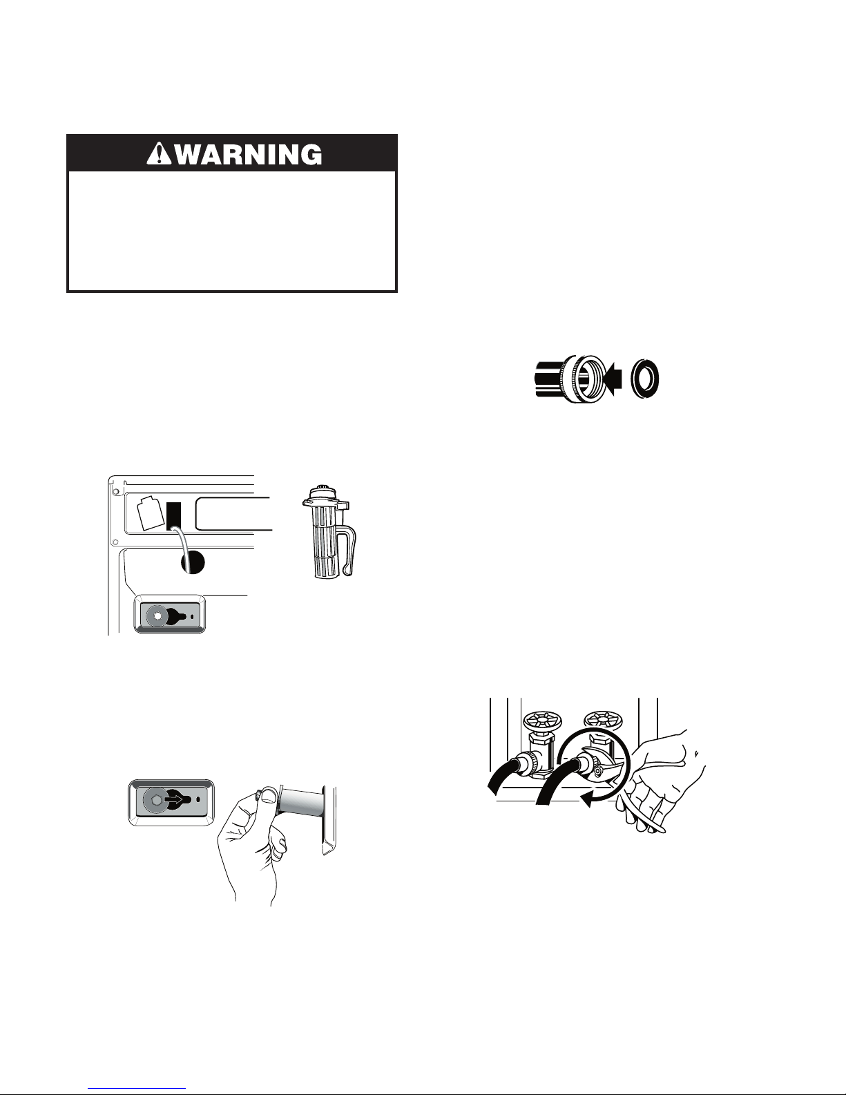
CONNECT THE INLET HOSES
Insert new flat washers (supplied) into each
end of the inlet hoses. Firmly seat the wash
ers in the couplings.
Connect the inlet hoses to the water faucets
Make sure the washer drum is empty.
-
1. Using a 13 mm wrench, loosen each of
the bolts.
2. Once the bolt is loose, move it to the center of the hole and completely pull out the
bolt, including the plastic spacer covering
the bolt.
3. Once all 4 bolts are removed, discard the
bolts and spacers. Then pull the power
cord through the opening of the rear panel and close the hole with the attached
cap.
1. Attach a hose to the hot water faucet.
Screw on coupling by hand until it is seat
ed on the washer.
2. Attach a hose to the cold water faucet.
Screw on coupling by hand until it is seat
ed on the washer.
3. Using pliers, tighten the couplings with
an additional two-thirds turn.
NOTE: Do not overtighten or use tape
or sealants on the valve. Damage to the
valves can result.
-
-
2-6
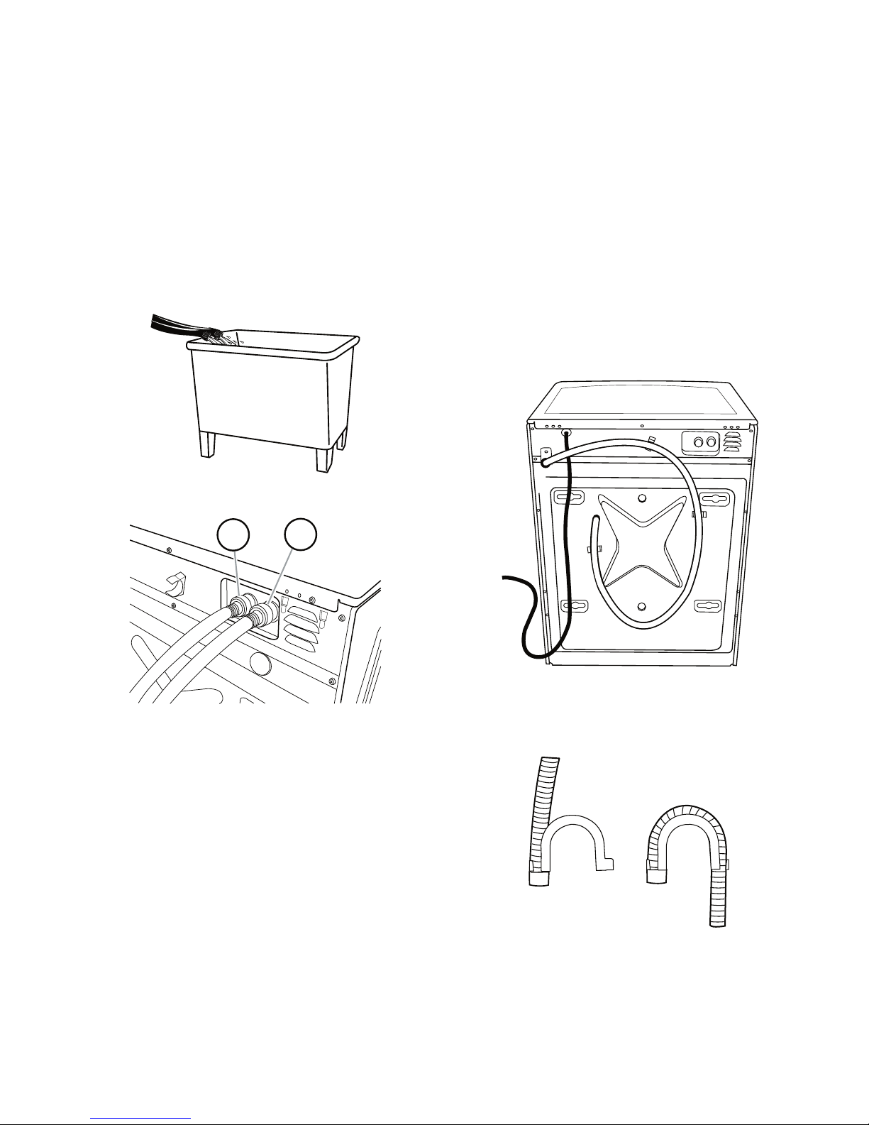
Clear the water lines
H. Hot water inlet
C. Cold water inle
t
H
C
A
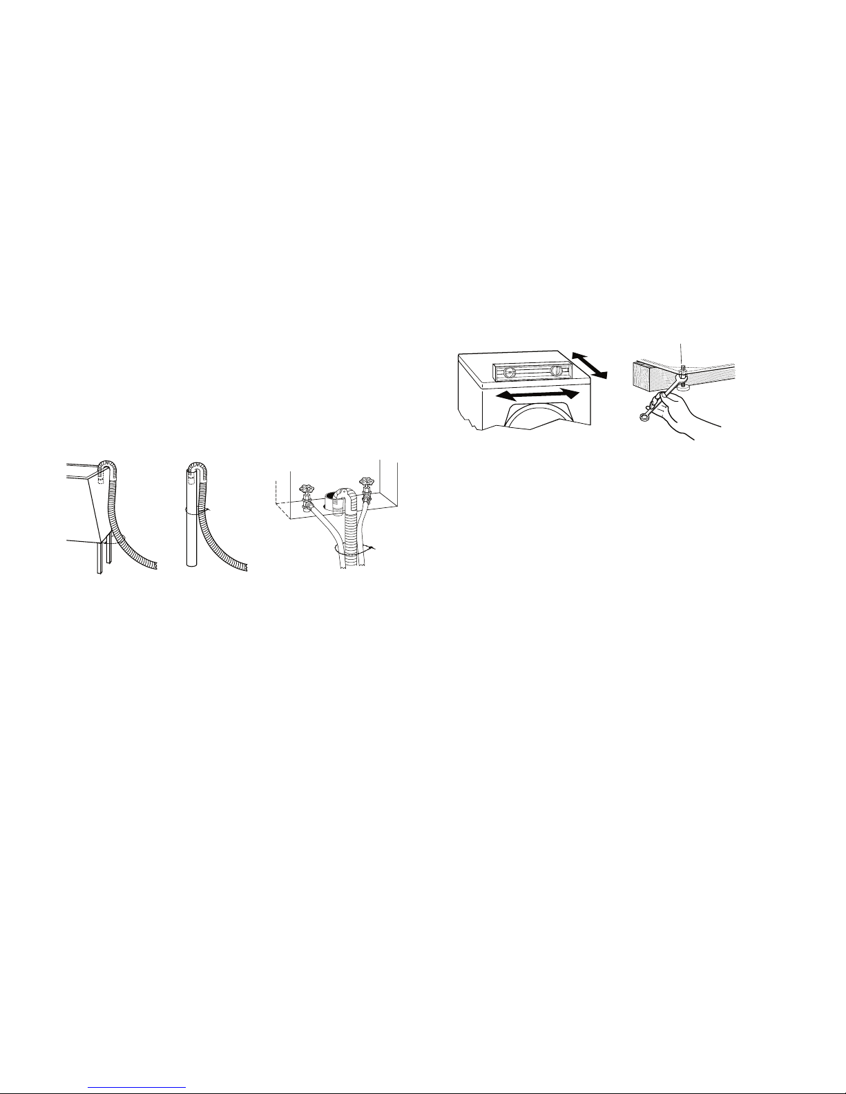
. Snap either end of the drain hose form to the drain hose at
the point where the corrugation begins.
B. Bend drain hose over drain hose form an
d snap into place.
A B
1. Run water through both faucets and inlet hoses, into a laundry tub, drainpipe or
bucket, to get rid of particles in the wa
ter lines that might clog the inlet valve
screens.
NOTE: Replace inlet hoses after 5 years of
use to reduce the risk of hose failure. Record
hose installation or replacement dates on the
hoses for future reference.
Periodically inspect and replace hoses if bulges, kinks, cuts, wear, or leaks are found.
2. Check the temperature of the water to
make sure that the hot water hose is con
nected to the hot water faucet and that
the cold water hose is connected to the
cold water faucet.
Connect the inlet hoses to the washer
ROUTE THE DRAIN HOSE
Proper routing of the drain hose protects your
floors from damage due to water leakage.
Read and follow these instructions.
Remove drain hose from the washer
Gently pull the corrugated drain hose from the
shipping clips.
1. Attach the hot water hose to the wash
er’s hot (H) water inlet valve. Screw on
coupling by hand until it is seated on the
washer.
2. Attach the cold water hose to the washer’s
cold (C) water faucet. Screw on coupling
by hand until it is seated on the washer.
3. Using pliers, tighten the couplings with
an additional two-thirds turn.
NOTE: Do not overtighten. Damage to
the coupling can result.
4. Turn on the water faucets completely and
check for leaks.
Laundry tub drain or standpipe drain
Connect the drain hose form to the corrugated
drain hose.
-
2-7
To keep drain water from going back into
A B C
the washer:
Do not straighten the drain hose, and do
•
not force excess drain hose into standpipe.
Hose should be secure, but loose enough
to provide a gap for air.
Do not lay excess hose on the bottom of
•
the laundry tub.
Floor drain
You may need additional parts. See Floor
Drain under “Tools and Parts.”
SECURE THE DRAIN HOSE
1. Drape the power cord over the washer
top.
2. Move the washer to its final location.
3. Place the drain hose in the laundry tub or
standpipe. See illustrations A and B.
LEVEL THE WASHER
One foot has been installed at a different
height on your new washer. The other three
feet were preset at the factory. Properly level
ing your washer will minimize excessive noise
and vibration.
1. Push on the upper front panel to be sure
that the washer is on the rear feet. Low
er the right front foot until it contacts the
floor. Check the levelness of the washer
by placing a level on the top edge of the
washer, first side to side, then front to
back.
If the washer is against a wall, move the
washer out slightly before tipping back.
First prop the front with a wood block and
adjust the feet as necessary; then prop
the back and adjust feet as necessary.
Repeat this step until washer is level.
-
-
4. If the washer faucets and the drain standpipe are recessed, put the hooked end of
the drain hose in the standpipe. See il
lustration C.
NOTES:
Do not force excess drain hose back into
•
the rear of the washer.
To prevent siphoning, do not seal the drain
•
hose into the standpipe.
2. Make sure that all four feet are stable and
resting on the floor. Then check that the
appliance is perfectly level (use a level).
3. After the washer is level, use a 17 mm
open-end wrench to turn the nuts on the
feet tightly against the washer cabinet.
IMPORTANT: All four feet must be tight-
ened. If the nuts are not tight against the
washer cabinet, the washer may vibrate.
4. When you are pushing on the edges of
the washing machine top plate, the ma
chine should not move front to back, side
to side, or diagonally.
5. Slide the washer to its final location.
6. Confirm the levelness of the washer.
-
2-8

COMPLETE INSTALLATION
Use only HE High Efficiency detergent.
1. Check the electrical requirements. Be
sure that you have the correct electrical
supply and the recommended grounding
method. See “Electrical Requirements.”
2. Check to be sure all parts are now installed. If there is an extra part, go back
through the steps to see which step was
skipped.
3. Check that you have all of your tools.
4. Dispose of or recycle all packaging materials.
5. Check that the water faucets are on.
6. Check for leaks around faucets and inlet
hoses.
Electrical Shock Hazard
Plug into a grounded 3 prong outlet.
Do not remove ground prong.
Do not use an adapter.
Do not use an extension cord.
Failure to follow these instructions can
result in death, fire, or electrical shock.
7. Plug into a grounded 3 prong outlet.
8. Read “Washer Use.”
9. To test and to clean your washer, use
1/2 the manufacturer’s recommended
amount for a medium sized load. Pour
the detergent into the detergent dispenser. Select NORMAL/CASUAL, and then
select START. Allow the washer to com
plete one whole cycle.
-
2-9

— NOTES —
2-10

PRODUCT OPERATION
FEATURES AND BENEFITS
The front-loading high efficiency washer was
designed to conserve resources and lower your
water and energy bills. The washer is designed
to determine and then provide the amount of
water needed for the best performance. The
time of operation may be greater for this new
system than for a conventional washer.
ELECTRONIC CONTROLS
Flexible electronic controls are easy to use
whether you are a beginner or an expert.
AUTO WATER LEVEL
Adjusting to the size of the load, this feature
allows the washer to use the minimal amount
of water needed to clean and rinse the clothes.
With a low water level, you can obtain the
same results with smaller amounts of additives.
Because only the required amount of water is
used, the washer saves energy, too. You can
obtain the same washing results for small and
large loads size.
STAINLESS STEEL DRUM
The stainless steel drum eliminates corrosion
and enables higher spin speeds for more water
extraction, reducing drying time.
ADAPTIVE VARIABLE
SPEED MOTOR
The motor adapts to the load size and to the
cycle selected to give the optimum cleaning,
rinsing, and spinning conditions. The motor can
handle slow speeds needed for delicate items
and is powerful enough to drive an average
clothes load up to a high-speed spin.
SPIN SPEEDS
This washer automatically selects the spin
speed based on the cycle selected. For some
cycles, the default spin speed can be changed
if desired. This washer offers up to three different spin speed choices.
ADD A GARMENT
LARGER LOAD SIZE
Since there is no agitator, you can wash larger,
bulkier items such as an average size sleeping
bag. You are also able to wash more clothes at
one time, which means fewer loads. You can
wash a pillow or a large stuffed teddy bear.
SUSPENSION SYSTEM
To reduce washer “walk” and “off-balance”
conditions, your new washer combines:
2 Springs to isolate vibration
•
3 or 4 shock absorbers at the washer base
•
to minimize movement
This option is available in all wash cycles
except Rinse/Spin and Drain/Spin. When this
option is available at the beginning of the cycle
the Add A Garment status light will illuminate
for the first 7 minutes. This washer allows a
7-minute period in which forgotten garments
may be added to a load.
DYNAMIC BALANCE
A precision balancing system allows the washer
to reach high-speed spins. The washer spins
faster so that clothes coming out of the washer
will have less moisture than with traditional top
load machines. In addition, if the Dynamic Bal
ance system detects off-balance loads during
spinning, it redistributes the clothes so that they
are evenly balanced.
-
3-1

SMART DISPENSERS
Use only HE High Efficiency detergent.
The three compartments in the dispenser
allow loading of all laundry additives before
the washer is started. The additives will be
dispensed into the wash at the optimal time
for high performance cleaning. The bleach
release system is included in the detergent
advantage system. The detergent is added at
the beginning of the cycle, and the bleach is
added after the enzymes have had a chance
to do their cleaning. The fabric softener is
dispensed in the rinse cycle or in the EXTRA
RINSE, if selected. The Detergent Advantage
System Dispenser tray is easily removed for
cleaning.
3-2
WASHER USE
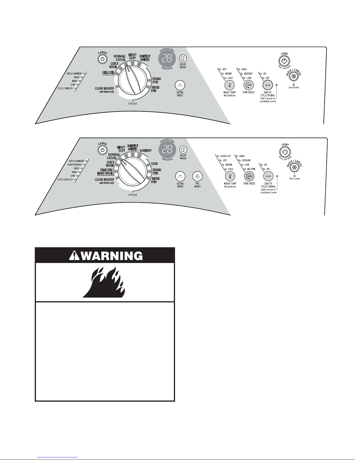
MODEL WFW8300S
MODEL WFW8500S
STARTING THE WASHER
Fire Hazard
Never place items in the washer that
are dampened with gasoline or other
flammable fluids.
No washer can completely remove oil.
Do not dry anything that has ever had
any type of oil on it (including cooking
oils).
WARNING: To reduce the risk of fire, electric
shock, or injury to persons, read the IMPOR
TANT SAFETY INSTRUCTIONS before operat
ing this appliance.
The following is a guide to using the washer.
Please refer to specific sections of this manual
for more detailed information.
Do not store laundry products on the top surface of this washer. Vibration is normal during
operation.
-
-
Doing so can result in death, explosion,
or fire.
3-3

USING THE PROPER DETERGENT
Use only HE High Efficiency detergent.
Use only High Efficiency detergents. The package for this type of detergent will be marked
“HE” or “High Efficiency.” This wash system,
along with less water, will create too much
sudsing with a regular non-HE detergent. Us
ing regular detergent will likely result in washer
errors, longer cycle times, and reduced rinsing
performance. It may also result in component
failures and noticeable mold or mildew. HE de
tergents are made to produce the right amount
of suds for the best performance. Follow the
manufacturer’s instructions to determine the
amount of detergent to use.
When unloading garments, occasionally
•
check under the rubber rim at the front
of the tub for small items.
2. Close the washer door by pushing it firmly
until the lock clicks. The washer door will
-
remain locked during the wash cycle.
NOTE: After any wash cycle is completed,
the door must be opened and then closed
before a new cycle can begin. The door
-
can be opened only if PAUSE/CANCEL
is selected while the ADD A GARMENT
light is illuminated or if the cycle has been
canceled. See “To cancel a cycle” in the
“Changing Cycles and Options Section.”
3. Open the dispenser drawer and add laundry additives to the detergent, bleach,
or fabric softener compartments. Close
drawer slowly to avoid spills. See “Using
the Dispenser.”
First Wash Cycle Without Laundry
Before washing clothes for the first time, if not
completed during the final installation step,
choose the Normal/Casual cycle and run it
without clothes. Use only HE High Efficiency
detergent. Use 1/2 the manufacturer’s recom
mended amount for a medium-sized load. This
initial cycle serves to ensure the interior is clean
before washing clothes.
For All Wash Cycles
1. To load washer
Open the washer door by pulling on the
handle. Sort laundry according to color and
type of fabric. Place a load of sorted clothes
in the washer. Do not overload washer.
Overloading can cause poor cleaning.
The washer can be fully loaded, but
•
not tightly packed. Washer door should
close easily.
•
Mix large and small items. Avoid wash
ing a single item. Load evenly.
Wash small items such as infant socks
•
in mesh garment bags. It is recommend
ed that more than one garment bag be
used and that each garment bag be
filled with equal amounts of material.
4. Turn on the washer by selecting POWER.
Select one of the cycles by turning the cycle
selector. The indicator light for the selected
cycle will illuminate. When selecting a
Wash Cycle, the preset Modifiers and Op
-
tions, Water Temp, and Spin Speed for the
selected cycle will illuminate. The preset
settings provide the recommended fabric
care for the selected cycle. See “Wash
Cycles.”
5. Select the desired OPTIONS. Not all Options are available with all cycles. See
“Options.”
6. If desired, select the END OF CYCLE
SIGNAL. The signal is helpful when you
are washing items that should be removed
from the washer as soon as it stops. Press
END OF CYCLE SIGNAL to select ON or
OFF.
7. To begin the wash cycle immediately
-
Select and hold START (for approximately
1 second).
If you do not select START within 5 min-
•
-
utes of choosing a cycle, the washer
automatically shuts off.
-
3-4
When the wash cycle is complete, the
Use only HE High Efficiency detergent.
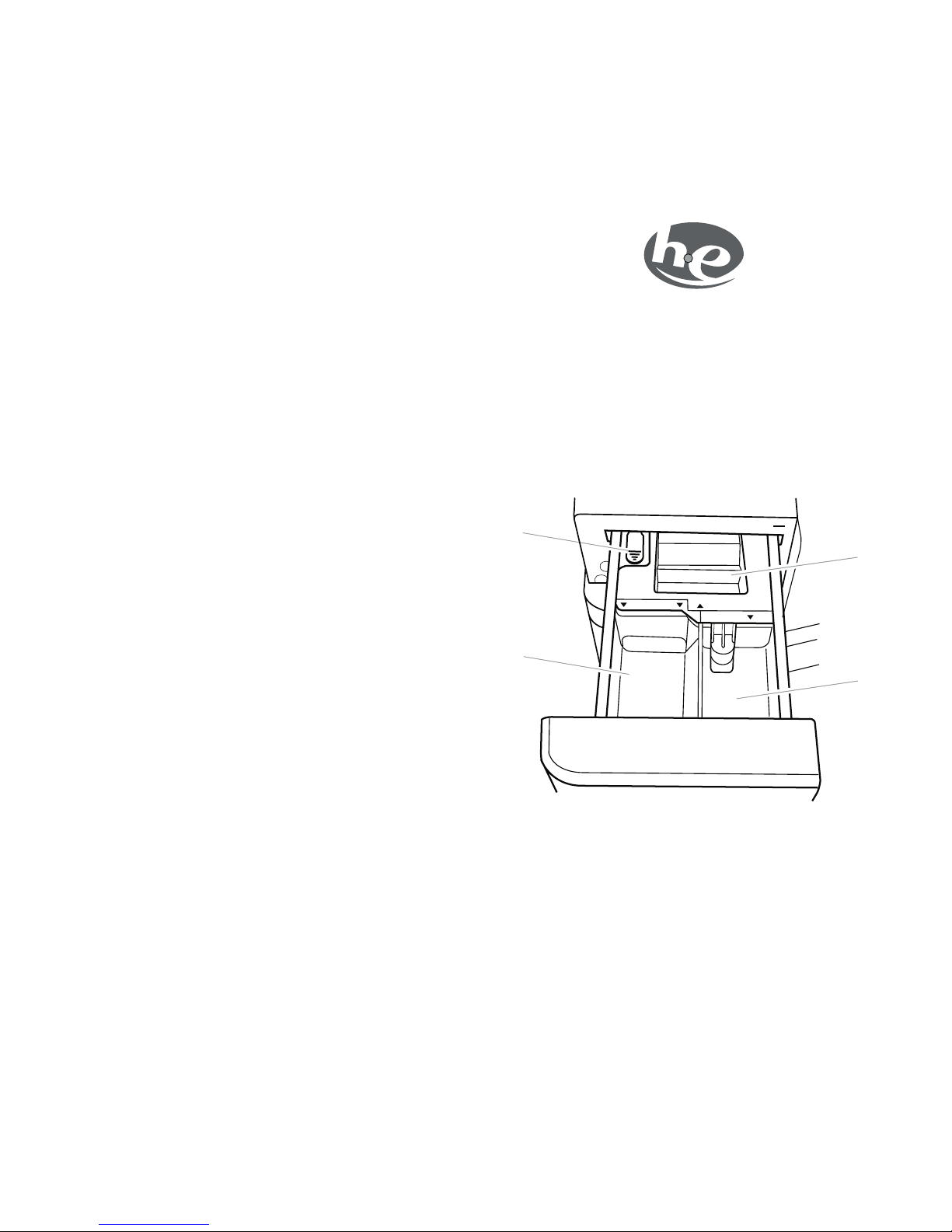
Dispenser
A. Dispenser release leve
r
B. Main Wash detergent compartmen
t
C. Liquid
chlorine bleach compartment
D. Fabric softener comp
artment
DETERGENT
LIQUID BLEACH
SOFTENER
MAX
A
B
C
D
MA
X
• performance. It may also result in component
CYCLE COMPLETE status light illumi
nates, the door unlocks, and the wash
load can be removed from the washer.
The washer powers down automatically
5 minutes after the cycle is complete
-
failures and noticeable mold or mildew. HE de
tergents are made to produce the right amount
of suds for the best performance. Follow the
manufacturer’s instructions to determine the
amount of detergent to use.
and the CYCLE COMPLETE light goes
off. To power down the washer manually
after the wash cycle is complete, select
PAUSE/CANCEL once.
8. To begin the wash cycle later
-
Select DELAY WASH until the desired
delay time (in hours) is displayed. Select
START. The countdown to the wash cycle
will show in the display window.
IMPORTANT: When delaying a cycle, use
only powdered detergents in the main wash
compartment since liquid detergents may
seep out of the compartment during Delay,
before the wash cycle begins.
USING THE DISPENSER
The washer has a dispenser drawer with three
separate compartments for your laundry ad
ditives—one is for detergent, one is for liquid
chlorine bleach, and one is for liquid fabric
softener. Laundry additives are diluted and
dispensed automatically at the proper time
during the wash cycle, making it unnecessary
for you to return to the washer during the cycle
to add them.
It is normal for small amounts of water to remain in the dispensers when the wash cycle
is complete.
To fill dispenser compartments
1. Pull out the dispenser drawer.
2. Add the desired laundry additives to the
proper compartment.
3. Push in the dispenser drawer slowly and
completely (to avoid a spill).
-
Do not put laundry additives directly into the
wash tub. Always use the proper dispensers
when adding laundry additives.
Choosing the Right Detergent
Use only High Efficiency detergents. The package for this type of detergent will be marked
“HE” or “High Efficiency.” This wash system,
along with less water, will create too much
sudsing with a regular non-HE detergent. Us
ing regular detergent will likely result in washer
errors, longer cycle times, and reduced rinsing
Main Wash detergent compartment
(Letter B in Dispenser Illustration)
Add liquid or powdered HE detergent to this
compartment for your main wash cycle.
Powdered color-safe bleach may be added
•
-
to the Main Wash compartment along with
the powdered detergent.
3-5

Liquid detergent: Measure the amount of
•
liquid detergent with the measurement de
vice which comes with the detergent. Add no
more than the manufacturer’s recommended
amount. The liquid detergent flows immediately into the washer.
Powdered detergent: Measure the amount of
•
powdered detergent with the measurement
device which comes with the detergent. Add
no more than the manufacturer’s recommended amount.
NOTE: Overfilling could cause an oversudsing
condition.
Chlorine bleach compartment
(Letter C in Dispenser Illustration)
CHANGING CYCLES AND OPTIONS
Not all Options are available with all Cycles.
Cycles and Options can be changed anytime
before START is selected.
To stop a cycle and select a new cycle
1. Select PAUSE/CANCEL once.
2. Select desired cycle.
3. Select the desired OPTIONS.
4. Select and hold START (for approximately
1 second) to restart the washer at the
beginning of the new cycle.
To cancel a cycle
1. Select PAUSE/CANCEL twice.
Add NO MORE THAN 2/3 cup (160 mL) liquid
chlorine bleach to this compartment. The bleach
will be automatically diluted and dispensed
at the best time during the first rinse after the
wash cycle. This compartment cannot dilute
powdered bleach.
Use only liquid chlorine bleach in this dis-
•
penser. Do not use this dispenser to add
powdered chlorine or any form of colorsafe
bleach to your load.
Always measure liquid chlorine bleach. Use
•
a measuring cup with a pour spout; do not
guess. Follow the manufacturer’s directions
for proper use.
Do not fill beyond the “MAX” level.
•
NOTE: Overfilling could cause garment dam-
age.
Fabric softener compartment
(Letter D in Dispenser Illustration)
Add 1/4 cup (60 mL) liquid fabric softener to
this compartment. Fabric softener will be auto
matically dispensed in the final rinse or in the
EXTRA RINSE, if selected.
2. The washer powers down, the door unlocks, and clothes can be removed.
NOTE: If the water level or the temperature is
too high, the washer will drain automatically
before the door unlocks.
To change Options after the cycle has
started
1. Select PAUSE/CANCEL once.
2. Select the desired OPTIONS. If the option
is not available, the machine will beep.
3. Select and hold START (for approximately
1 second) to continue the cycle.
To drain the washer manually
1. Select PAUSE/CANCEL.
2. Select DRAIN/SPIN.
3. Select and hold START (for approximately
1 second) to begin the drain.
4. When the spin is complete, the door
-
unlocks. Items can be removed from the
washer.
STATUS LIGHTS
Do not fill beyond the “MAX” level.
•
PAUSING OR RESTARTING
1. To pause the washer at any time, select
PAUSE/CANCEL.
2. To continue the cycle, select and hold
START (for approximately 1 second).
These lights show which portion of the cycle the
washer is operating. They also indicate when
you can add an additional item to the wash
cycle and when the controls are locked.
3-6

Adding items
Estimated Time Remaining
You can add items to the washer after the wash
cycle has started, if the ADD A GARMENT status
light is illuminated. All cycles have this feature
except Rinse/Spin and Drain/Spin.
To add items
1. Select PAUSE/CANCEL. The washer door
unlocks, and items can be added.
2. To continue the cycle, close the door and
select and hold START (for approximately
1 second).
3. To unlock the door after the Add a Garment
period, press PAUSE/CANCEL twice. This
will cancel the Wash Cycle.
Cycle Complete
The Cycle Complete light stays on for 5 minutes after the cycle is complete. The washer
will then power down.
Locking controls
The Control Lock avoids unintended use of
the washer. You can also use the control lock
feature to avoid unintended cycle or option
changes during a cycle. When CONTROL
LOCKED is lit, all buttons are disabled except
for PAUSE/CANCEL and START. You can lock
the controls while the washer is operating.
The cycle times vary automatically based on
your water pressure, water temperature, deter
gent, and clothes load. The cycle time will be
extended if oversudsing occurs or the load is
unbalanced. The SUDs routine removes extra
suds and assures proper rinsing of your gar
ments. The options you select will also affect
the cycle times that are shown in the Preset
Cycle Settings table. The Estimated Time Remaining can change up to 30 minutes under
extreme conditions.
Door Locked
When the status light illuminates, the door
is locked. The door is locked and unlocked
automatically, depending on the stage of the
wash cycle.
CYCLES
Wash Cycles
Choose Wash Cycles by rotating the Cycle selector knob to the desired cycle. The indicator
light for the cycle selected will illuminate. Each
cycle is designed for different types of fabric
and soil levels.
-
-
To lock the controls
Select and hold END OF CYCLE SIGNAL for
3 seconds. The CONTROL LOCKED status
light illuminates.
To unlock the controls
Select and hold END OF CYCLE SIGNAL for 3
seconds until the CONTROL LOCKED Status
light turns off.
3-7
•
Each cycle has a preset cycle time, WASH
TEMP, SPIN SPEED, and may have preset
Options. The preset settings provide the
recommended fabric care for the selected
cycle.
The preset settings can be changed anytime
•
before START is selected. Not all Options and
Modifiers (WASH TEMP, SPIN SPEED) are
available with all Cycles. To change settings
after the cycle has started, select PAUSE/
CANCEL, then select the desired settings.
Select and hold START (for approximately
1 second) to continue the cycle.

Cycle
Estimated
Time
*
(hr:min)
Wash Temp Spin Speed
Sanitary
3:00 S
uper Hot High
153°F (67°C)
140°F (60°C)
140°F (60°C)
95°F (35°C)
95°F (35°C)
95°F (35°C)
68°F (20°C)
68°F (20°C)
Whitest Whites
2:00 H
ot High
Heavy Du
ty
2:00 H
ot High
Normal/Casua
l
0:5
6 Warm High
Quick Wash
(2-3 items)
0:25 Warm Hig
h
Delicate/
Hand
Wash
0:39 Warm Low
Clean Wa
sher
0:56 N
/A Low
Rinse/Spin
0:26 C
old High
Drain/Spin
0:14 N
/A High
Soak
0:29 C
old No Spin
Preset Cycle Settings
Whitest Whites
Each cycle has a preset Cycle Time, WASH/
RINSE TEMP, and SPIN SPEED. The preset
settings provide the recommended fabric care
for the selected cycle. See chart.
* The cycle times vary automatically based
on your water pressure, water temperature,
detergent, and clothes load. The cycle time
will be extended if oversudsing occurs or the
load is unbalanced.
Sanitary
Use this cycle to clean heavily soiled, colorfast
fabrics. This cycle combines a super hot water
temperature and fast speed tumbling to help
ensure the removal of heavy soils and stains.
It is recommended that you set your hot water
heater to 120ºF (49ºC) to ensure proper per
formance during this cycle. The Sanitary cycle
also helps eliminate 99.999% of 3 common in
fectious bacteria, even when no bleach is used.
High-speed spin helps shorten drying time.
This cycle is especially designed for cleaning
loads of soiled white fabrics with the addition
of bleach. Hot washing temperatures assure
optimal bleach activity. An additional rinse
provides optimal rinse performance to avoid
chlorine residues on your laundry. This cycle
combines fast-speed tumbling, longer wash
time, and high-speed spin to shorten drying
time. It also includes Extra Rinse as a preset
setting.
Heavy Duty
Use this cycle to wash loads of sturdy, colorfast
fabrics and Heavy soiled garments. This cycle
combines fast-speed tumbling, longer wash
time, and high-speed spin to shorten drying
times.
Normal/Casual
Use this cycle to wash loads of no-iron fabrics
such as sport shirts, blouses, casual business
clothes, permanent press blends, cottons and
linens, and synthetic fabrics. This cycle combines medium-speed tumbling, high-speed
spin, and a load cooling process to reduce
wrinkling.
Quick Wash
Use this cycle to wash small loads of 2-3 lightly
soiled garments that are needed in a hurry.
This cycle combines fast-speed tumbling, a
shortened wash time, and high-speed spin to
shorten drying time. Large wash loads will re
sult in the machine increasing the wash time.
Delicate/Hand Wash
Use this cycle to wash sheer fabrics, lingerie,
-
hand washable, and special-care garments.
This cycle combines low-speed tumbling and
low-speed spin for gentle fabric care.
Use mesh garment bags to wash undergar-
•
ments such as underwire bras, items with
strings, and small items such as socks.
3-8
-

Clean Washer
Use the Clean Washer cycle once a month to
keep the inside of your washer fresh and clean.
This cycle uses a higher water level in combi
nation with liquid chlorine bleach to thoroughly
clean the inside of your washing machine. See
“Cleaning The Washer.”
IMPORTANT: Do not place garments or other
items in the washer during the Clean Washer
cycle. Use this cycle with an empty wash tub.
Rinse/Spin
Use this cycle to get a rinse and spin only. This
cycle combines fast-speed tumbling and highspeed spin. If desired, you can reduce the spin
speed by selecting the speed you want from
the SPIN SPEED modifier.
Rinse & Spin is useful for:
•
Loads that need rinsing only.
•
Adding fabric softener to a load using the
fabric softener dispenser.
NORMAL SOUNDS
As with any new product, you will hear sounds
that you are not accustomed to. You may hear
-
various sounds when the door is locked or
unlocked, and during the washing, rinsing, or
spinning process. Between changes in wash
actions, there will be momentary pauses. You
will hear water spraying and splashing during
the wash and rinse cycles. These new sounds
and pauses are part of normal washer opera
tion. See “Troubleshooting.”
OPTIONS AND MODIFIERS
You can customize your wash by adding options to your cycle selections. You can add or
change an option after starting a cycle anytime
before the selected option begins. Not all options are available with all cycles.
-
Drain/Spin
Use this cycle to drain your washer or to drain
and spin your wash load. The spin speed is
preset to HIGH. If desired, you can reduce the
spin speed by selecting the speed you want
from the SPIN SPEED modifier.
NOTE: Loads of synthetics, delicate fabrics,
handwashables, and woolens should be
drained with no spin or low spin to avoid fabric
stress.
Soak
Use the Soak cycle to help remove small spots
of set-in stains on fabrics. This cycle provides
a soak time with warm or cold water, followed
by drain. Extra water, a short tumbling phase
for equal distribution of the laundry, and a
soaking time without drum movement, to help
improve the removal of set-in stains. Drain
without spin assures gentle treatment, even
for delicate items.
See the “Laundry Guide” section for an
•
overview of possible options for each Wash
Cycle selection.
If an option is available with a selected cycle,
•
the light for that option will illuminate when
selected.
•
If an option is unavailable with a selected
cycle, there will be a short tone and the
light for that option will not illuminate when
selected.
Delay Wash
Use this to begin the wash cycle later.
Select DELAY WASH until the desired time
•
(in hours) shows in the Estimated Time Remaining display.
3-9
•
Select START. The countdown to the wash
cycle will show in the display window.

Extra Rinse
Wash Water Temperature Suggested Fabrics
SUPER HO
T Sturdy colorfast fabrics
Heavy soil
s
HO
T Whites and pastels
Heavy soil
s
WARM Bright colors
Moderate to light soil
s
COLD Colors that bleed or fad
e
Light soils
An extra rinse can be used to aid in the removal
of detergent or bleach residue from garments.
This option provides an additional rinse with the
same water temperature as in the normal rinse.
It is a preset setting for the Whitest Whites
cycle. You may select or deselect by pressing
EXTRA RINSE.
Prewash
Use this option for loads of heavily soiled garments that need pretreatment.
Add detergent to the Main Wash Compart-
•
ment of the dispenser drawer.
•
Use powdered detergent to keep laundry
additives from predispensing into the wash
system.
This option adds tumbling time prior to the
selected main cycle. The washer continues
automatically from prewash into the main wash
cycle.
Wash Temp
Each cycle has a preset water temperature
setting. To change the water temperature, se
lect the WASH TEMP button until the desired
setting is illuminated.
Select a water temperature based on the type
of load you are washing. Use the warmest
wash water safe for fabrics. Follow garment
label instructions.
The water temperature for all rinse cycles is
cold. Cold rinses save energy.
Temperature Guide
In wash water temperatures colder than 60°F
(15.6°C), detergents do not dissolve well. Soils
may be difficult to remove.
Auto Temp Control
ATC (Auto Temp Control) electronically senses
and maintains a uniform water temperature.
ATC regulates incoming hot and cold water.
The ATC is automatically turned ON when a
cycle is selected. See Preset Cycle Settings
table in “Cycles.”
ATC works for the wash temperature with
•
Warm and Cold settings.
•
The Cold rinse temperatures depend on the
cold water at the faucet.
Spin Speed
Each cycle has a preset SPIN SPEED. To
change the spin speed, select the SPIN
SPEED button until the desired setting is il
luminated.
-
End of Cycle Signal
This signal is helpful when you are removing
items from the washer as soon as it stops.
Select ON or OFF.
3-10

LAUNDRY GUIDE
CYCLE SUGGESTED LOAD TYPE AVAILABLE OPTIONS
Delay
Wash
Extra
Rinse
Pre
Wash
End of
Cycle Signal
Sanitary Heavily soiled underwear, towels, work cloths, diapers, etc.
Whitest Whites Soiled white fabrics
Heavy Duty Heavily soiled underwear, towels, shirts, etc., made of cotton
Normal/Casual Normally soiled blouses, shirts, overalls, etc., made of
polyester,
nylon, cotton, linen, or cotton blends
Quick Wash Small
loads of 2-3 lightly soiled cotton, polyester, nylon, and
cotton blends
Delicate
/
Hand
Wash
Curtains and delicate clothing, dresses, skirts, shirts and
blouses, fabrics made of silk, and special care items marked
“Hand Wa
shable”
Clean Wa
sher No clothes
Rinse & Spin All loads
Drain & Spin All load
s
Soak All load
s
Refer to the chart below for suggested load types and their corresponding cycles. Listed to the
right are the options available to each of these washer cycles.
3-11
 Loading...