


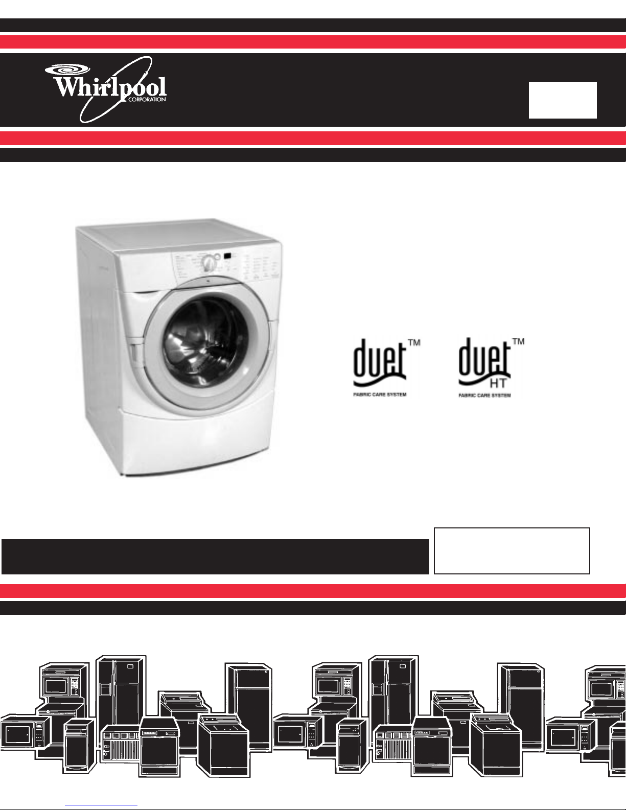
GHW9200L
Whirlpool GHW9200L, GHW9100LW, GHW9100LQ, GHW9200LW, GHW9200LQ Service Manual
...
CONSUMER SERVICES TECHNICAL
EDUCATION GROUP PRESENTS
Front-Loading
Automatic Washer
L-68
Model Numbers:
GHW9100L GHW9200L
JOB AID
Part No. 8178076
i

FORWARD
This Whirlpool Job Aid, “Front-Loading Automatic Washer,” (Part No. 8178076), provides the technician
with information on the installation and service of the Front-Loading Automatic Washer. It is to be used
as a training Job Aid and Service Manual. For specific information on the model being serviced, refer to
the “Use and Care Guide” or “Tech Sheet” provided with the washer.
The Wiring Diagram used in this Job Aid is typical and should be used for training purposes only. Always
use the Wiring Diagram supplied with the product when servicing the unit.
GOAL AND OBJECTIVES
The goal of this Job Aid is to provide detailed information that will enable the service technician to properly diagnose malfunctions and repair the Whirlpool Front-Loading Automatic Washer.
The objectives of this Job Aid are:
• Understand and follow proper safety precautions.
• Successfully troubleshoot and diagnose malfunctions.
• Successfully perform necessary repairs.
• Successfully return the washer to its proper operational status.
WHIRLPOOL CORPORATION assumes no responsibility for any repairs
on our products by anyone other than Authorized Service Technicians.
Copyright 2001, Whirlpool Corporation, Benton Harbor, MI 49022
CORPORATION
ii

TABLE OF CONTENTS
GENERAL INFORMATION ....................................................................................................... 1-1
Safety First ................................................................................................................... ...... 1-1
Model/Serial Number Designators ................................................................................... 1-2
Specifications..................................................................................................................... 1-3
Pedestal Warranty.............................................................................................................. 1-3
Washer Warranty ............................................................................................................... 1-4
INSTALLATION CONSIDERATIONS....................................................................................... 2-1
Installation Requirements................................................................................................. 2-1
Installation Instructions (Washer).................................................................................... 2-3
Installation Instructions (Pedestal) .................................................................................. 2-6
THEORY OF OPERATION ....................................................................................................... 3-1
COMPONENT ACCESS............................................................................................................ 4-1
Component Location ......................................................................................................... 4-1
Component Access ........................................................................................................... 4-2
COMPONENT TESTING........................................................................................................... 5-1
Central Control Unit........................................................................................................... 5-1
Component Checks ........................................................................................................... 5-2
Motor Control Unit ............................................................................................................. 5-4
Line Filter.................................................................................................................... ........ 5-5
Dispenser............................................................................................................................ 5-5
Pressure Switch ................................................................................................................. 5-6
Heating Element and Temperature Sensor ..................................................................... 5-6
DIAGNOSIS AND TROUBLESHOOTING ................................................................................ 6-1
Suds Detection................................................................................................................... 6-1
Door Locking and Unlocking ............................................................................................ 6-2
Unbalance Detection Routine ........................................................................................... 6-3
Error Codes ........................................................................................................................ 6-4
Diagnostic Test .................................................................................................................. 6-8
Troubleshooting Chart ...................................................................................................... 6-10
Cycle Charts ....................................................................................................................... 6-12
WIRING DIAGRAM ................................................................................................................... 7-1
TECH TIPS ................................................................................................................................ 8-1
iii

-- NOTES --
iv
GENERAL
IMPORTANT SAFETY INFORMATION
Your safety and the safety of others are very important.
We have provided many important safety messages in this manual and on the appliance. Always read
and obey all safety messages.
This is the safety alert symbol.
This symbol alerts you to potential hazards that can kill or hurt you and others.
!
All safety messages will tell you what the potential hazard is, tell you how to reduce the chance of injury,
and tell you what you can happen if the instructions are not followed.
All safety messages will follow the safety alert symbol and either the word “DANGER”
or “WARNING.” These words mean:
You can be killed or seriously injured if you
! DANGER
WARNING!
don’t immediately follow instructions.
You can be killed or seriously injured if you
don’t follow instructions.
! WARNING
ELECTRICAL SHOCK HAZARD
Disconnect power before servicing.
Replace all panels before operating.
Failure to do so can result in death or
electrical shock.
! WARNING
Excessive Weight Hazard
Use two or more people to move and
install washer.
Failure to do so can result in back or
other injury.
! WARNING
ELECTRICAL SHOCK HAZARD
Plug into a grounded 3 prong outlet.
Do not remove ground prong.
Do not use adapter.
Do not use an extension cord.
Failure to follow these instructions can
result in death, fire, or electrical shock.
1 - 1
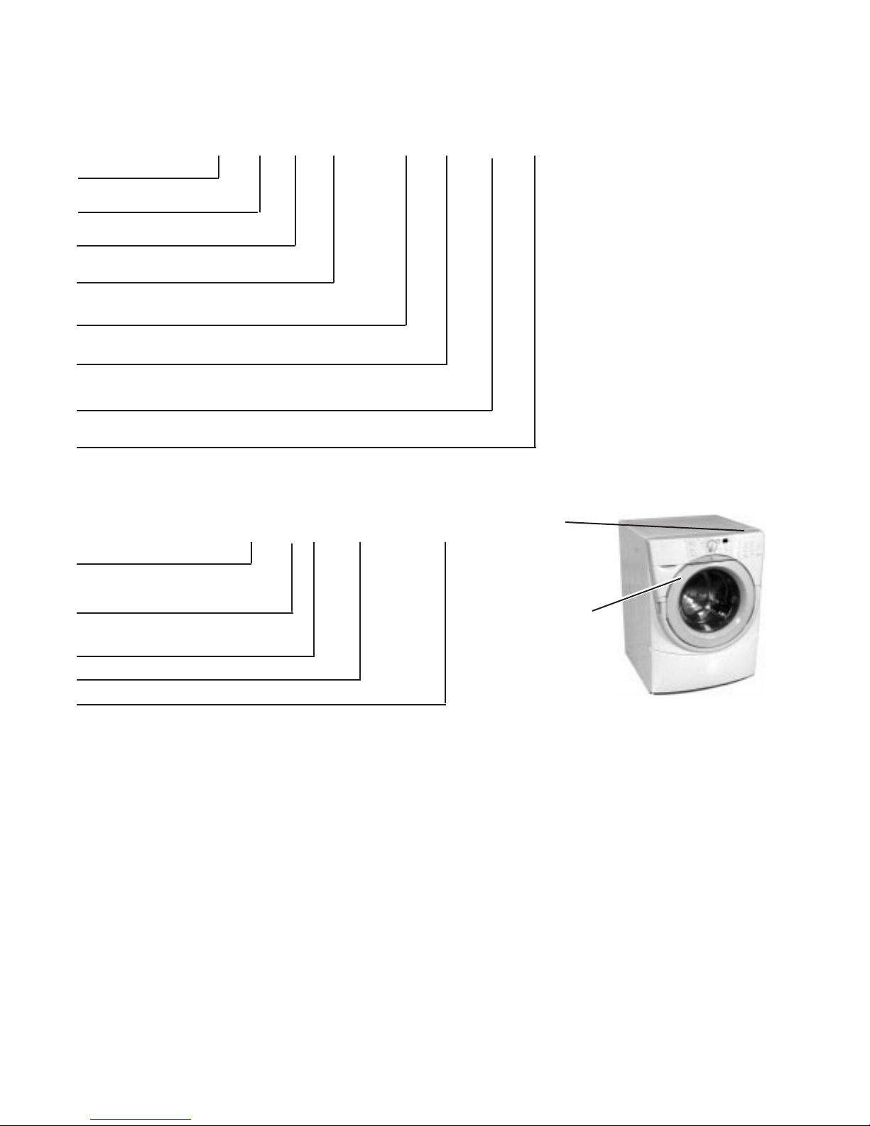
WHIRLPOOL MODEL & SERIAL NUMBER DESIGNATORS
MODEL NUMBER
MODEL NUMBER
PRODUCT GROUP
G = Gold Line Laundry
PRODUCT IDENTIFICATION
H = Horizontal Axis - Domestic
FEATURE CODE
W = Resource Saving
FEATURE CODE
9100 = Non-Heated
9200 = Heated
YEAR OF INTRODUCTION
L = 2002
COLOR CODE
W = White/Grey
Q = White/Blue
ENGINEERING CHANGE
0 = Basic Release; 1 = First Revision; 2 = Second Revision
GW 0H 9100 WL
SERIAL NUMBER
SERIAL NUMBER
MANUFACTURING SITE
CS = Schorndorf, Germany
YEAR OF MANUFACTURE
L = 2001
WEEK OF MANUFACTURE
PRODUCT SEQUENCE NUMBER
CS L 36 50001
Tech Sheet
(Right Side
Panel)
Model/Serial
Number Plate
(Left side of
Door Opening)
1 - 2
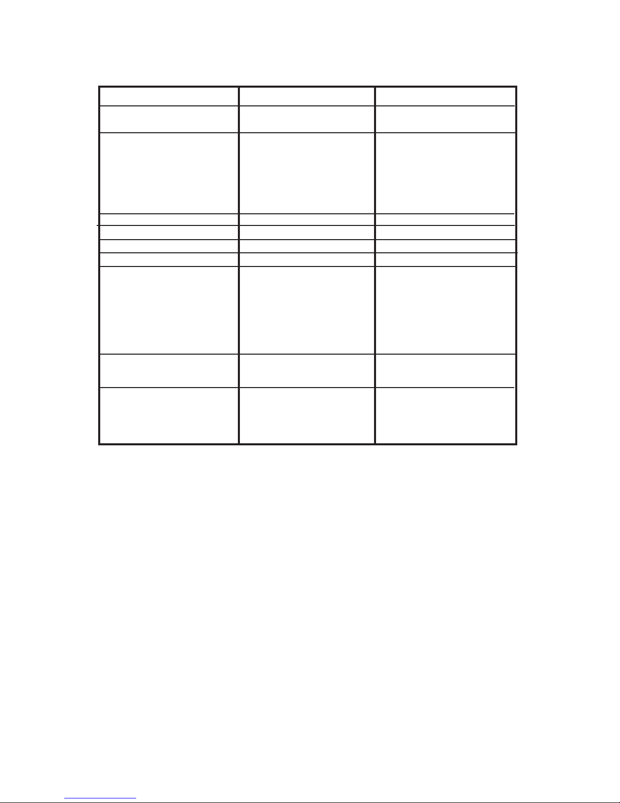
SPECIFICATIONS
Model Number
Color
Electrical Requirements
Heating Power
Max. Current
Rated Current
Voltage
Frequency
Gallons/Normal Cycle
Capacity
V olume
Max. Spin Speeds
Dimensions
Height
Height (Feet Extended)
Width
Depth
Weight
Installation Options
Programs
Program Selector
Temperature Selector
Spin Speed
GHW9100LW/Q
W = White/Grey
Q = White/Blue
No Heating Element
12A
15A
120V
60Hz
15.8 Gal./60 L
19.8 lbs. (9 kg.)
3.7 cu. ft. (IEC equivalent)
900 RPM
37.4” (950mm)
38.2” (970mm)
27” (686mm)
30.3” (770mm)
245 lbs. (111kg.)
Pedestal
Stackable
Rotary 8 Programs
Buttons (3 levels)
Buttons (4 levels)
GHW9200LW/Q
W = White/Grey
Q = White/Blue
1,000W
12A
15A
120V
60 Hz
15.8 Gal./60 L
19.8 lbs. (9 kg.)
3.7 cu. ft. (IEC equivalent)
1100 RPM
37.4” (950mm)
38.2” (970mm)
27” (686mm)
30.3” (770mm)
245 lbs. (111kg.)
Pedestal
Stackable
Rotary 12 Programs
Buttons (5 levels)
Buttons (5 levels)
WHIRLPOOL PEDESTAL WARRANTY
Full One-Year Warranty on Mechanical parts.
For one year from the date of purchase, when this Pedestal is installed with the listed washer or dryer and
operated according to the instructions provided in the washer or dryer Owner’s Manual or Use and Care Guide,
supplier will repair or replace any of its mechanical parts if defective in material or workmanship.
Warranty Restriction
If the Pedestal is subject to other than private family use and or used with any other product than those listed in
the installation instructions, the warranty is null and void.
1 - 3

WARRANTY
WHIRLPOOL WASHER WARRANTY
LENGTH OF
WARRANTY:
FULL ONE-YEAR
WARRANTY
FROM DATE OF
PURCHASE
LIMITED
TWO-YEAR
WARRANTY
FROM DATE OF
PURCHASE
LIMITED
FIVE-YEAR
WARRANTY
FROM DATE OF
PURCHASE
LIMITED
FIVE-YEAR
WARRANTY
FROM DATE OF
PURCHASE
WHIRLPOOL WILL PAY FOR: WHIRLPOOL WILL NOT PAY FOR:
FSP® replacement parts and repair
labor costs to correct defects in
materials or workmanship. Service
must be provided by a Whirlpooldesignated service company.
For two years from the date of
purchase, FSP® replacement parts
only to correct defects in the electronic control boards if defective in
material or workmanship.
For five years from the date of
purchase, FSP® replacement parts
only to correct defects in the drive
system belt and pulley if defective in
material or workmanship.
For five years from the date of
purchase, FSP® replacement parts
only to correct defects in the porcelain top, (GHW9200), or powder coat
top, (GHW9100), if defective in
material or workmanship.
A: Service calls to:
1.Correct the installation of the washer
2.Instruct you how to use the washer.
3.Replace house fuses or correct
house wiring.
B. Repairs when the washer is used in
other than normal, single-family house
hold use.
C. Pickup and delivery. The washer is
designed to be repaired in the home.
D. Damage to the washer caused by
accident, alterations, misuse, abuse,
fire, flood, acts of God, or use of
products not approved by Whirlpool.
E. Repairs to parts or systems resulting
from unauthorized modifications made
to the washer.
F. Replacement parts or repair labor costs
for units operated outside the United
States.
LIMITED
TEN-YEAR
WARRANTY
FROM DATE OF
For ten years from the date of
purchase, FSP® replacement parts
only to correct defects in the plastic
tub if defective in material or workmanship.
PURCHASE
LIMITED
LIFE-TIME
WARRANTY
FROM DATE OF
For the life of the washer from the
date of purchase, FSP® replacement
parts only to correct defects in the
stainless steel basket if defective in
material or workmanship.
PURCHASE
1 - 4
INST ALLATION INFORMA TION
INSTALLATION
REQUIREMENTS
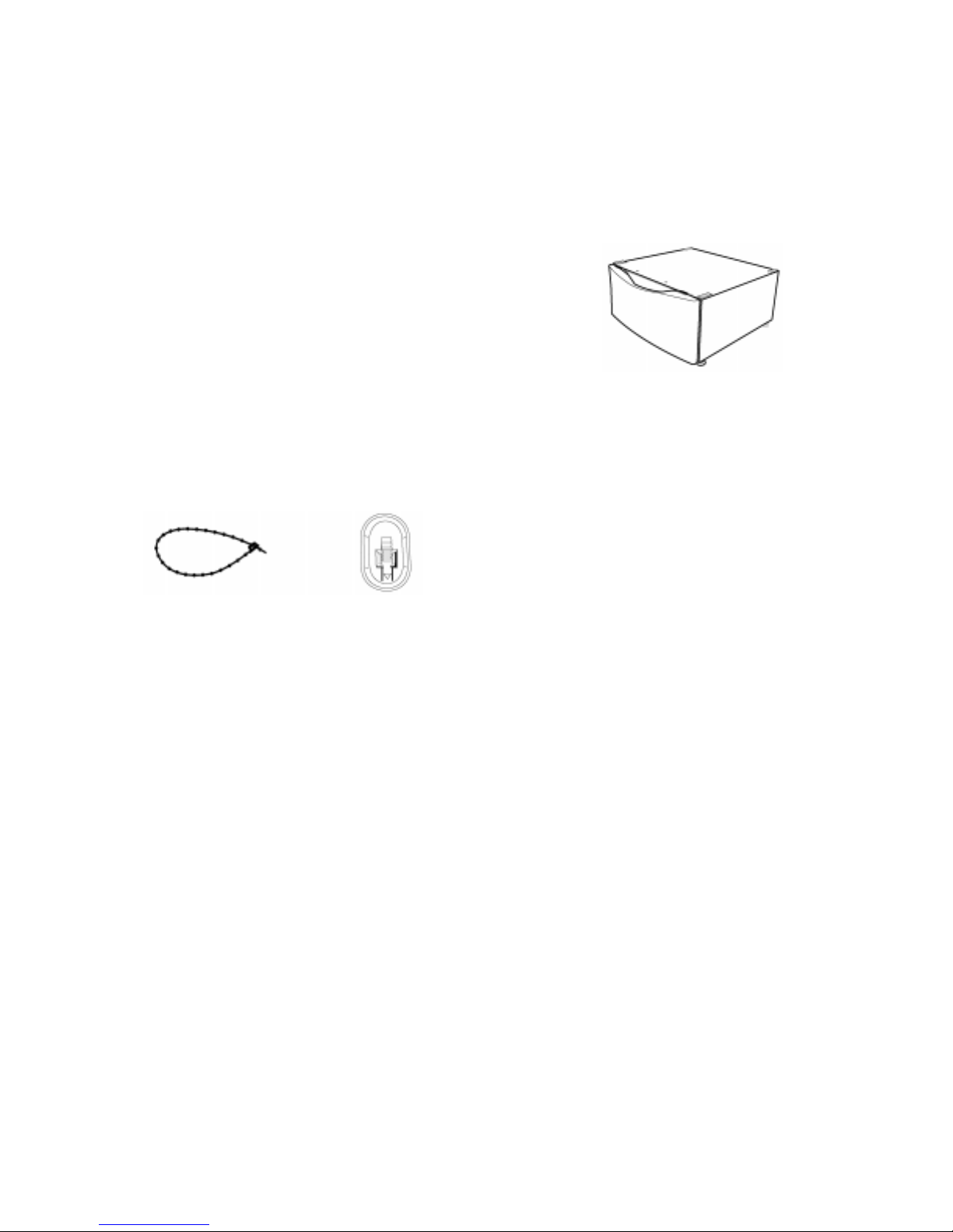
T ools and Parts
Assemble the necessary tools and supplies before beginning the washer installation. The parts supplied are
in the washer basket.
Tools needed for connecting the water inlet hoses
• Pliers (that open to 1 9/16 in.)
• Flashlight (optional)
Tools needed for installation
• Open end wrench 5/8 in. (17 mm) and ½ in. (13
mm)
• Level
• Wood block (2" x 4")
• Ruler or measuring tape
Parts supplied:
Beaded strap
Alternate Parts You May Need
If You Have
Laundry tub or
standpipe taller
than 96 in. (2.4 m)
Overhead sewer
Floor drain
Drain hose too short
You Will Need to Buy
Sump pump system (if not already available)
Standard 20 gal. (76 L), 30 in.
(76.2 cm) tall drain tub or utility sink and sump pump (available from local plumbing suppliers)
Siphon break, Part Number
285834; additional drain hose
Part Number 8318155; and
connector kit, Part Number
285835
Drain hose extension kit, Part
Number 285863
Transport Bolt Hole
Plug (4)
Optional Pedestal
A pedestal may be purchased separately for this
washer. This pedestal will add about 14 inches to the
height of your unit for a total vertical height of approximately 52 inches (132 cm).
Optional Pedestal
Location Requirements
Selecting the proper location for your washer improves
performance and minimizes noise and possible washer
“walk.”
Your washer can be installed under a custom counter,
or in a basement, laundry room, closet, or recessed
area. (See “Drain System.”)
Companion appliance location requirements should
also be considered. Proper installation is your responsibility.
You will need
• A water heater set to deliver 120°F (49°C) water
to the washer.
• A grounded electrical outlet located within 5 ft.
(1.5 m) of where the power cord is attached to the
back of the washer. (See “Electrical Requirements.”)
• Hot and cold water faucets located within 4 ft.
(1.2 m) of the hot and cold water fill valves, and
water pressure of 20-100 psi (137.9-689.6 kPa).
• A level floor with a maximum slope of 1 in.
(2.5 cm) under entire washer. Installing the washer
on carpeting is not recommended.
• A sturdy and solid floor to support the washer with
a total weight (water and load) of 400 lbs. (180
kg).
Do not operate your washer in temperatures below
32°F (0°C). Some water can remain in the washer and
can cause damage in low temperatures.
Water faucets beyond
reach of fill hoses
2 longer water fill hoses:
6 ft. (1.8 m) Part Number
76314, 10 ft. (3.0 m) Part Number 350008
2 - 1
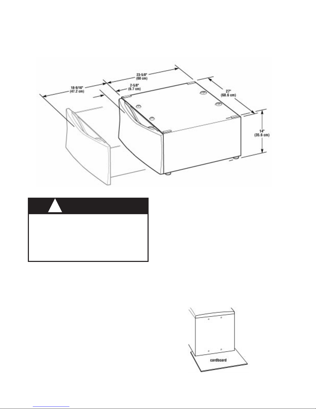
Washer Dimensions
Drain System
The washer can be installed using the standpipe drain
system (floor or wall), the laundry tub drain system, or
the floor drain system. Select the drain hose installation method you need. (See “Alternate Parts You May
Need.”)
Custom undercounter installation
The dimensions shown are for the minimum spacing
allowed.
Recessed area or closet installation
The dimensions shown are for the minimum spacing
allowed.
•
Additional spacing should be considered for ease
of installation and servicing.
• Additional clearances might be required for wall,
door and floor moldings.
• Additional spacing of 1 in. (2.5 cm) on all sides of
the washer is recommended to reduce noise transfer.
• For closet installation, with a door, the minimum
ventilation openings in the top and bottom of the
door are required (view 2). Louvered doors with
equivalent ventilation openings in the top and bottom are acceptable.
Standpipe drain system - wall or floor (view 1 & 2)
The standpipe drain requires a minimum diameter
standpipe of 2 in. (5 cm). The minimum carry-away
capacity can be no less than 17 gal (64 L) per minute.
The top of the standpipe must be at least 30 in. (76.2
cm) high and no higher than 96 in. (2.4 m) from the
bottom of the washer.
Laundry tub drain system (view 1)
The laundry tub needs a minimum 20 gal. (76 L) capacity. The top of the laundry tub must be at least 30
in. (76.2 cm) above the floor.
Floor drain system (view 2)
The floor drain system requires a siphon break that
may be purchased separately. (See “Alternate Parts
You May Need.”)
The siphon break must be a minimum of 28 in. (71
cm) from the bottom of the washer. Additional hoses
might be needed.
2 - 2

Electrical Requirements
! WARNING
ELECTRICAL SHOCK HAZARD
Plug into a grounded 3 prong outlet.
Do not remove ground plug.
Do not use an adapter.
Do not use an extension cord.
Failure to follow these instructions can
result in death or electrical shock.
• A 120-volt, 60-Hz., AC-only, 15- or 20-ampere,
fused electrical supply is required. Time-delay fuse
or circuit breaker is recommended. It is recommended that a separate circuit serving only this
appliance be provided.
• This washer is equipped with a power supply cord
having a 3 prong ground plug.
• To minimize possible shock hazard, the cord must
be plugged into a mating, 3 prong, ground-type
outlet, grounded in accordance with local codes
and ordinances. If a mating outlet is not available,
it is the personal responsibility and obligation of
the customer to have the properly grounded outlet installed by a qualified electrician.
• If codes permit and a separate ground wire is used,
it is recommended that a qualified electrician determine that the ground path is adequate.
• Do not ground to a gas pipe.
• Check with a qualified electrician if you are not
sure the washer is properly grounded.
• Do not have a fuse in the neutral or ground circuit.
GROUNDING INSTRUCTIONS
For a grounded, cord-connected washer:
This washer must be grounded. In the event of a
malfunction or breakdown, grounding will reduce
the risk of electrical shock by providing a path of
least resistance for electric current. This washer
is equipped with a cord having an equipmentgrounding conductor and a grounding plug. The
plug must be plugged into an appropriate outlet
that is properly installed and grounded in accordance with all local codes and ordinances.
WARNING: Improper connection of the equipment-grounding conductor can result in a risk of
electric shock. Check with a qualified electrician
or serviceman if you are in doubt as to whether
the appliance is properly grounded.
Do not modify the plug provided with the appliance –
if it will not fit the outlet, have a proper outlet installed by a qualified electrician.
For a permanently connected washer:
This washer must be connected to a grounded
metal, permanent wiring system, or an equipment
grounding conductor must be run with the circuit
conductors and connected to the equipmentgrounding terminal or lead on the appliance.
INSTALLATION
INSTRUCTIONS
Remove Transport System
! WARNING
Excessive Weight Hazard
Use two or more people to move and install washer.
Failure to do so can result in back or other
injury.
IMPORTANT: Position the washer so that the rear
of the unit is within approximately 3 feet (90 cm)
of the final location.
2 - 3
There are 4 bolts in the rear panel of the washer that
support the suspension system during transportation.
1. Using a ½ in. (13 mm) wrench, loosen each of the
bolts.
2. Once the bolt is loose, move it to the center of the
hole and completely pull out the bolt, including the
plastic spacer covering the bolt and the cable
attached to the bolt. The power cord will be attached to all 4 bolts.
3. Once all 4 bolts are removed, remove the power
cord from each bolt holder, and discard bolts,
plastic spacers, and cables.
4. Close the holes with the transport bolt hole plugs.
Route the Drain Hose
Proper routing of the drain hose protects your floors
from damage due to water leakage. Carefully read and
follow these instructions.
The drain hose is connected to your washer.
Connect the Inlet Hoses
Connect the inlet hoses to the water faucets
Make sure the washer basket is empty.
1. Attach the hose with the red color indicator to the
hot water faucet. Screw on coupling by hand until
it is seated on the washer.
2. Attach the hose with the blue color indicator to the
cold water faucet. Screw on coupling by hand until it is seated on thewasher.
3. Using pliers, tighten the couplings with an additional two-thirds turn.
NOTE: Do not overtighten. Damage to the coupling
can result.
4. Turn on the water faucets and check for leaks.
NOTE: Replace inlet hoses after 5 years of use to
reduce the risk of hose failure. Record hose installation or replacement dates on the hoses for
future reference.
Periodically inspect and replace hoses if bulges,
kinks, cuts, wear, or leaks are found.
Secure the Drain Hose
1. Drape the power cord over the washer top.
2. Secure the drain hose to the laundry tub leg or
standpipe with the beaded strap provided. (See
illustration.)
To prevent drain water from going back into the
washer:
• Do not straighten the drain hose, and do not force
excess drain hose into standpipe. Hose should be
secure, but loose enough to provide a gap for air.
• Do not lay excess hose on the bottom of the laun
dry tub.
Floor drain
Y ou may need additional parts. (See Floor Drain under
“Alternate Parts Y ou May Need.”)
If the washer faucets and the drain standpipe are
recessed, put the hooked end of the drain hose in
the standpipe. Tightly wrap the beaded strap around
the water inlet hoses and the drain hose.
Do not force excess drain hose into the standpipe.
2 - 4
Level the Washer
Properly leveling your washer prevents excessive
noise and vibration.
1. Check the levelness of the washer by placing a
level on the top edge of the washer, first side-toside, then front-to-back.
If the washer is against a wall, move the washer out
slightly before tipping back. If the washer is not level,
first prop the front with a wood block (2” x 4”) and adjust the feet as necessary; then prop the back and
adjust feet as necessary. Repeat this step until washer
is level.
2. After the washer is level, use a 5/8 in. (17 mm)
open-end wrench to turn the nuts on the feet tightly
against the washer cabinet. All 4 feet must be tightened. If the nuts are not tight against the washer
cabinet, the washer may vibrate.
3. Slide the washer to its final location.
4. Confirm the levelness of the washer.
3. Check to be sure you have all of your tools.
4. Dispose/recycle all packaging materials.
5. Check to be sure the water faucets are on.
6. Check for leaks around faucets and inlet hoses.
7. Plug into a grounded 3 prong outlet.
8. Read “Washer Use & Care Manual.”
To test and to clean your washer, measure ½ the
normal recommended amount of powdered or liquid
High Efficiency (HE) detergent or ¼ the normal
recommended amount of regular powdered or liquid
detergent. Pour the detergent into the detergent
dispenser. Select NORMAL/CASUAL, and then
select STAR T. Allow the washer to complete one
whole cycle.
Complete Installation
1. Check the electrical requirements. Be sure that
you have the correct electrical supply and the
recommended grounding method. (See “Electrical Requirements.”)
2. Check to be sure all parts are now installed. If
there is an extra part, go back through the steps
to see which step was skipped.
! WARNING
ELECTRICAL SHOCK HAZARD
Plug into a grounded 3 prong outlet.
Do not remove ground plug.
Do not use an adapter.
Do not use an extension cord.
Failure to follow these instructions can
result in death or electrical shock.
2 - 5
INSTALLATION INSTRUCTIONS
Pedestal
Fig. 2-1
! WARNING
EXCESSIVE WEIGHT HAZARD
Use two or more people to move washer
and dryer.
Failure to do so can result in back or other
injury.
Before you start...
Important: If the washer is already installed,
it must be uninstalled.
See installation instructions that came with the
washer for tools required.
Uninstalling the Washer
4. Remove the “HOT” and “COLD” fill
hoses from the back of the washer.
5. Disconnect the drain hose from the
washer and drain any water in the hose
into a bucket.
6. Pull the washer away from the wall so it
can be tipped on its back.
7. Protect the floor with a large piece of
cardboard cut from the pedestal carton.
Lay the washer on its back so that the
cardboard is under the entire lower back
edge of the washer.
“Installing the Pedestal”.
(Fig. 2-2)
Go to
1. Turn off the hot and cold water faucets.
2. Briefly start the wash cycle to release
any pressure in the fill hoses.
3. Unplug the power supply cord.
Fig. 2-2
2 - 6
Installing the Pedestal
1. Open the pedestal drawer. Remove
the envelope taped inside the drawer.
This envelope contains four (4)
#12 x 5/8” (1.6 cm) hex head sheet
metal screws that will be used in Steps
4 and 5.
2. Remove the Phillips head screw from
both drawer sides and set the aside.
(Fig. 2-3)
aside. Push the slides back into the
pedestal.
Remove the drawer and set it
Fig. 2-3
Fig. 2-5
Lift the pedestal toward the front of the
washer and install the two (2) remaining hex
head sheet metal screws. Tighten all four
screws completely.
6. Tip the washer and pedestal
assembly back to an upright position.
Remove protective cardboard.
3. The washer has feet already installed.
They must be removed, prior to installing
the pedestal.
4. Partially install the two (2) lower hex head
sheet metal screws leaving aspace of
about 3/8” (2 cm) between the screw head
and the bottom of the washer.
(Fig. 2-4)
Fig. 2-4
5. Move the pedestal against the washer
bottom. Slide the pedestal’s keyhole slots
over the lower two (2) partially installed
screws.
(Fig. 2-5)
7. Slide the washer close to its final
location.
8. Follow the Installation Instructions that
came with the washer to finish
installing or reinstalling. (i.e., hoses,
vents, etc.)
9. Level the washer from side to side
and front to back.
Place a level on the top. Locate the
1/4” hex nut on the top of each pedestal
foot. Reach inside thepedestal and use a
1/4” hex head ratchet or open-end wrench
to adjust the feet up or down as needed to
level the washer.
(Fig. 2-6)
Fig. 2-6
2 - 7
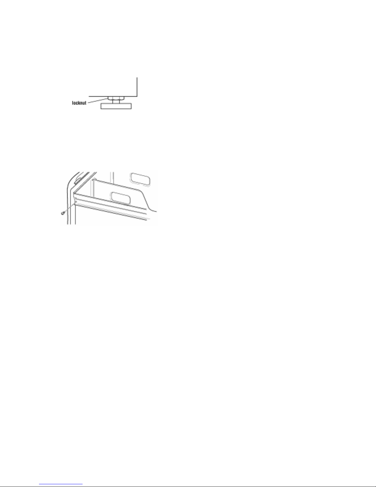
10. When the washer is level, use a
9/16” open-end wrench to securely
tighten all four (4) feet locknuts
against the pedestal.
(Fig. 2-7)
The
locknuts must be tightened.
Fig. 2-7
11. Pull both drawer slides out and reassemble the drawer to the drawer slides
with the two (2) Phillips head screws.
(Fig. 2-8)
Use of the two (2) dividers is
optional. Close the drawer.
Fig. 2-8
2 - 8
THEORY OF OPERATION
INTRODUCTION
The
operating characteristics quite different from previous models. In addition to the introduction of
front-loading operation, The washers
increase clothes cleaning ability while offering very high water and energy conservation.
Water System
The water system consists of the hot and cold water inlet valves, a water temperature sensor, a water
flowmeter and control and the dispenser distribution system along with a traditional pressure switch.
Water Inlet V alves -
The hot and cold water inlet valves are located at the back of the washer. These valves receive a control
signal from the Central Control Unit to manage the temperature of incoming water. The temperatures
are determined by the specific wash cycle selected and a temperature sensor located in the wash tub.
To improve cleaning of heavily soiled clothing and to provide a sanitizing feature, the water temperature can be increased through the use of a heating element located in the bottom of the tub, (GHW9200
model only).
and Front-Loading Automatic Washers present a number of new features and
contain a number of unique operating features designed to
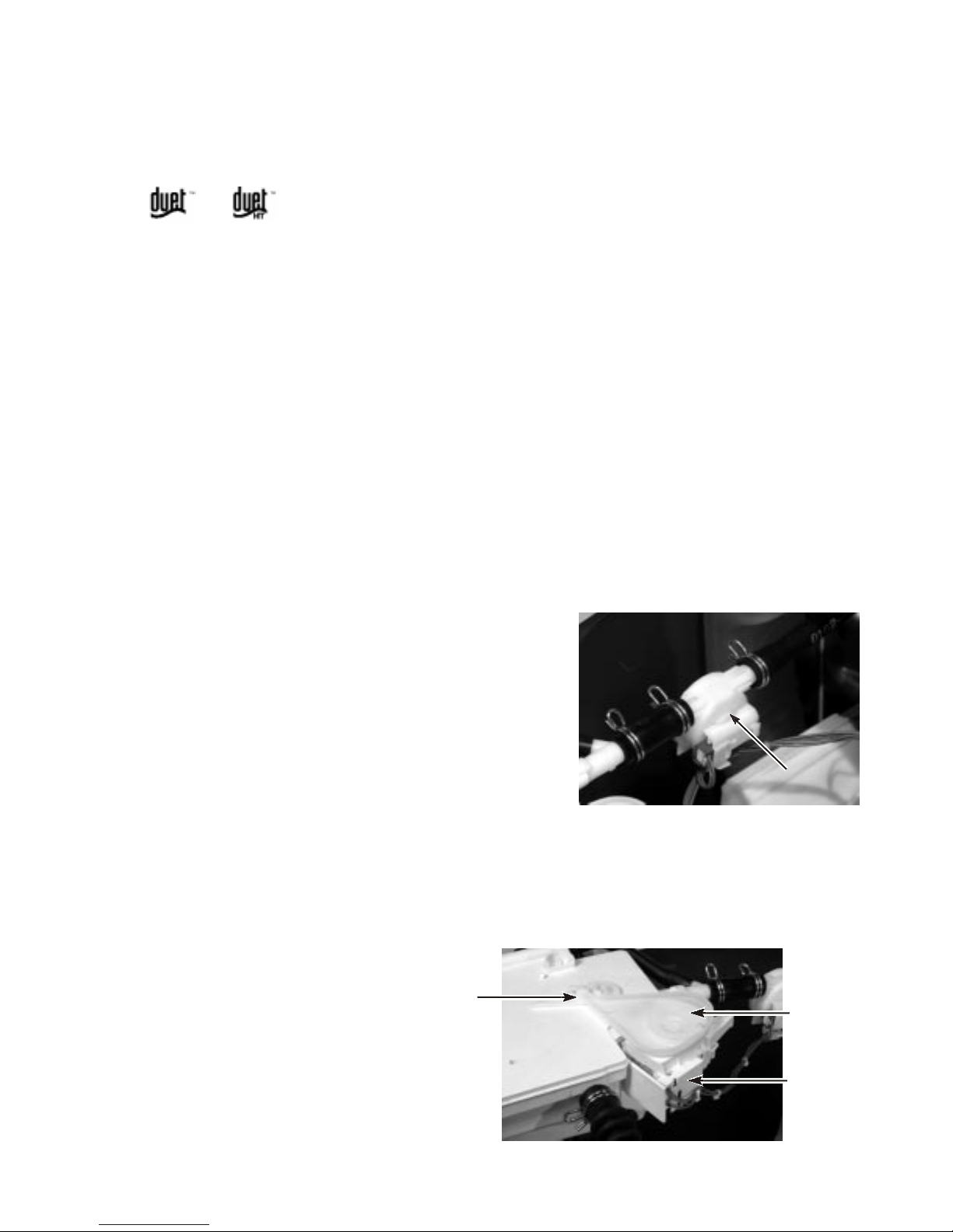
Flowmeter
Water flow, or the quantity of water introduced throughout
any cycle is monitored by a flowmeter and Central Control
Unit. When the flowmeter registers a maximum of 10.5 gal.
(40 L), and the Central Control Unit has not detected the
pressure switch trip, the water valves will be shut off and an
error code will show in the digital display. The flowmeter is
also used to introduce additional water into the tub for higher
water levels, based on cycle requirements. Refer to page 612 for more details.
Fig. 3-1
Flowmeter
Dispenser Distribution System
All wash and rinse water is introduced into the wash tub through a Dispenser Distribution System located in the top left corner of the washer. The system consists of a motor that turns a cam gear. The cam
follower will divert the incoming water to one or more of the follow water inlet modes:
• Detergent Dispensing
• Bleach Dispensing
• Fabric Softener Dispensing
• Rinse Dispensing (no additives)
Cam Follower
Cam
Dispenser
Motor
Fig. 3-2
3 - 1

The dispenser drawer has four separate compartments for
adding laundry products to the wash load. These compartments are:
1. Prewash Detergent Compartment
2. Main Wash Detergent Compartment
3. Bleach Compartment
4. Fabric Softener Compartment
Laundry products are diluted and dispensed automatically
at the proper time during the wash cycle.
The separator in the Prewash and Main Wash Detergent
Compartment can be moved to accommodate either liquid
or powdered detergents.
(Fig. 3-4)
The drawer release lever (shown here is the normal position) can be installed in alternate position (A) to accommodate stacking a matching dryer on top of the washer.
(Fig. 3-
4)
3
1
4
2
Fig. 3-3
Separator in Front Position
A
Refer to Use and Care Guide for the Front-Loading Automatic washer for proper use of laundry products.
There are two routes for the water to enter the wash tub.
Most of the water flows through the dispenser assembly. A
small portion of the water flow around the dispensers and
is used to wash the door window.
1. Main Inlet T ube
2. Window Washer Inlet Tube
(Fig. 3-5, A)
(Fig. 3-5, B)
Air V ent System
As a safety feature, the washer is designed to allow fresh
air to circulate through the tub. An inlet vent at the rear of
the washer brings air into the tub.
(Fig. 3-6A)
is vented through the dispenser assembly vent tube and
out the front of the dispenser drawer cutout.
Air Vent
The fresh air
(Fig. 3-6B)
Drawer Release
Lever
Fig. 3-4
B
A
Fig. 3-5
Vent
Tube
Fig. 3-6A
Vent
Tube
Fig. 3-6B
3 - 2
Pressure Switch
The pressure switch is located in the top right rear corner of
the washer.
(Fig. 3-7)
wash tub. The control signal from the pressure switch is
sent to the Central Control Unit and is used to determine the
amount of water introduced into the wash tub during the wash
cycle.
The pressure switch also senses the suds level in the wash
tub. If excessive sudsing occurs, the washer starts an automatic suds routine. The display will show the word “Sud”.
The automatic suds routine adds additional rinse and drain
operations until the suds level is reduced.
This switch senses water level in the
Pressure Switch
If an overfill condition is detected by the pressure switch, the
CCU will turn on the drain pump and attempt to stop filling.
Customer Interface and Cycle Selection
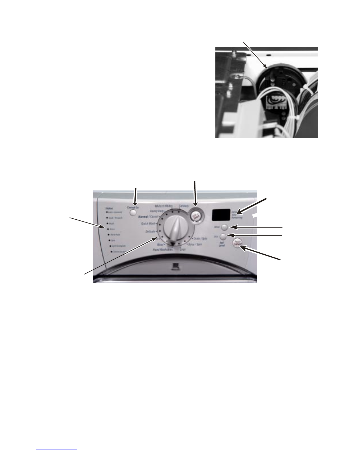
Control On
Status
Indicators
Push to
Start
Fig. 3-8
Wash Cycle
Selector
Control On - The Control On button must be
pressed before initiating any cycle selection.
Soil Level - Pressing this button will change the
length of the wash cycle. Heavy will add time to a
normal wash cycle, light will shorten a normal
Status Indicators - These lights show which
wash cycle.
portion of the cycle the washer is operating. They
also indicate when additional items can be added
to the wash cycle and when the controls are
locked.
Push to Start - The Push to Start button must be
pressed to initiate any wash cycle. Press and
hold the START button for one second.
Fig. 3-7
Display
Soil Level
(Change
Cycle Time)
Pause/
Cancel
Wash Cycle Selector - Choose a Wash Cycle
by turning the knob to the desired cycle. Each
cycle is designed for different types of fabric and
soil levels.
(See Table 3-1, Page 3-5)
Display - The display provides such information
as time remaining for selected wash cycle and
error codes.
Pause/Cancel - Pressing this button will allow
changing any option or changing a wash cycle
after the wash cycle has begun. Press the
PAUSE/CANCEL button, select the desired Op-
tion, press and hold the STAR T button for one (1)
second. T o cancel a cycle and select a new one,
press the PAUSE/CANCEL button, select the new
cycle, select the desired options, press and hold
the START button for one (1) second.
3 - 3

CYCLE DESCRIPTION
Sanitary
Use this cycle to clean heavily soiled colorfast fabrics. This cycle combines a very hot water temperature and fast speed tumbling to help ensure the removal of heavy soils and stains. It is recommended
that you set your hot water heater to 120º F (49º C) to ensure proper performance during this cycle.
The Sanitary cycle also helps kill bacteria, even when no bleach is used. Extra high speed spin helps
shorten drying time. The heating element in the tub will heat the wash water to 153°F during this cycle.
Whitest Whites
This cycle is especially designed for cleaning loads of soiled white fabrics with the addition of bleach.
Hot washing temperatures assure optimal bleach activity. An additional rinse provides optimal rinse
performance to avoid chlorine residues on your laundry. This cycle combines fast speed tumbling,
longer wash time, and extra high speed spin to shorten drying time.
Heavy Duty
Use this cycle to wash loads of sturdy, colorfast fabrics and normally soiled garments. This cycle
combines fast speed tumbling, longer wash time, and extra high speed spin to shorten drying times. If
the water temperature is lower than needed for this cycle, the heater will warm the water to the optimum temperature.
Normal/Casual
Use this cycle to wash loads of no-iron fabrics such as sport shirts, blouses, casual business clothes,
permanent press blends, cottons and linens, and synthetic fabrics. This cycle combines medium
speed tumbling, high speed spin, and a load cooling process to reduce wrinkling.
Quick W ash
Use this cycle to wash small loads of lightly soiled garments that are needed in a hurry. This cycle
combines fast speed tumbling, a shortened wash time, and extra high speed spin to shorten drying
time.
Delicate
Use this cycle to wash sheer fabrics and lingerie. This cycle combines low speed tumbling and low
speed spin for gentle fabric care.
Silk
Use this cycle to clean washable silk garments. (Check label instructions to make sure that garment
is washable.) This cycle gently tumbles and drains without spinning to gently clean garments and
minimize wrinkling. Because there is no spinning action, garments will contain a higher amount of
water at the end of this cycle.
Wool
Use this cycle to clean washable woolen garments. (Check label instructions to make sure that garment is washable.) This cycle features gentle tumbling and low speed spin to minimize creasing and
shrinkage.
Hand W ashables
Use this cycle to clean hand washable and special-care garments. Similar to the way garments are
hand washed in a sink, the wash action of this cycle combines periods of extra low speed tumbling
and soaking. Extra low speed spin reduces wrinkling.
3 - 4

PRESET CYCLE SETTINGS
Cycle
Sanitary
Whitest
Whites
Heavy
Duty
Normal/
Casual
Quick
Wash
Delicate
Silk
Soil level
(cycle time)
More
(120 min.)
More
(70 min.)
More
(90 min.)
Normal
(45 min.)
Less
(30 min.)
Normal
(35 min.)
Normal
(30 min.)
Water Temp
Extra Hot/Cold
Hot/Cold
Hot/Cold
Warm/Cold
Warm/Cold
Warm/Cold
Cold/Cold
Spin Speed
Extra High
Extra High
Extra High
High
Extra High
Medium
No Spin
Wool
Hand
Washables
Normal
(35 min.)
Normal
(35 min.)
Cold/Cold
Cold/Cold
Medium
Extra Low
T able 3-1
Soak
Use the Soak cycle to remove small spots of set-in stains on fabrics. This cycle provides a soak time
with warm or cold water followed by drain. Extra water, a short tumbling phase for equal distribution of
the laundry, and a soaking time without basket movement improve the removal of set-in stains. Drain
without spin assures gentle treatment even for delicate articles.
Rinse/Spin
Use the Rinse/Spin cycle to get a rinse and spin only. This cycle combines fast speed tumbling and
extra high speed spin. If desired, you can reduce the spin speed by selecting the speed you want from
the SPIN SPEED modifier. A Rinse/Spin cycle is useful for loads that need rinsing only or for adding
fabric softener to a load.
Drain/Spin
Use the Drain/Spin cycle to drain your washer or to drain and spin your wash load. The spin speed is
preset to extra high. If desired, you can reduce the spin speed by selecting the speed you want from
the SPIN SPEED modifier.
NOTE: Loads of synthetics, delicate fabrics, handwashables, and woolens should be drained with no
spin or low spin speed to avoid fabric stress.
3 - 5
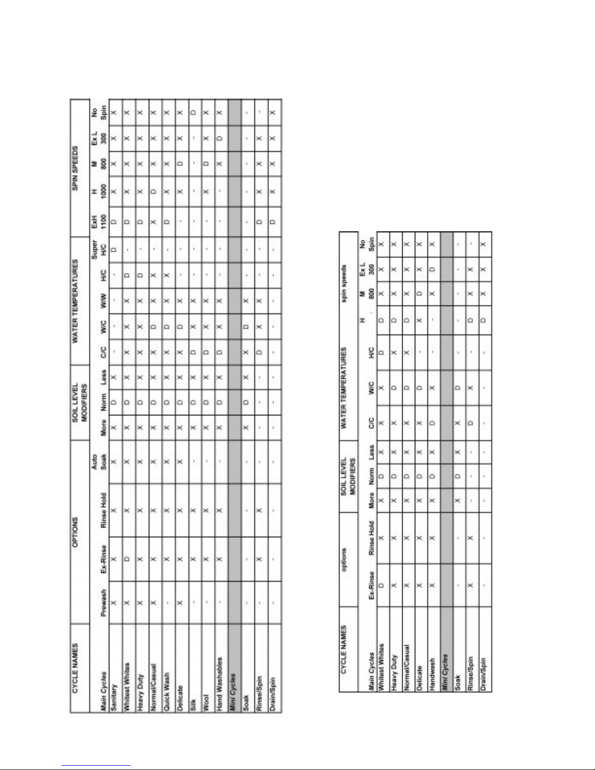
Option Selection
D = Default, X = Available, - = Not Available
900
Table 3-2
Table 3-3
MODEL GHW9200L
MODEL GHW9100L
3 - 6
 Loading...