


Cabrio W10164159B
Whirlpool Cabrio W10164159B, WED6600WL - 7.0 cu. ft. Cabrio Steam Dryer, Cabrio WED6600WL Use & Care Manual
®
®
CABRIO® STEAM FABRIC
CARE SYSTEM ELECTRIC
DRYER
Use & Care Guide
For questions about features, operation/performance,
parts, accessories or service call: 1-800-253-1301
In Canada, call: 1-
www.whirlpool.com or www.whirlpool.ca
or visit our website at
800-807-6777
SÉCHEUSE ÉLECTRIQUE
CABRIO® AVEC SYSTÈME DE
SOIN DES TISSUS
Guide d’utilisation et d’entretien
Au Canada, pour assistance, installation ou service, composez le :
Table of Contents/Table des matières ................. 2
1-800-807-6777
ou visitez notre site internet à
www.whirlpool.ca
W10164159B

TABLE OF CONTENTS
TABLE DES MATIÈRES
DRYER SAFETY..............................................................................3
INSTALLATION INSTRUCTIONS ..................................................4
Tools and Parts ............................................................................ 4
Location Requirements ...............................................................5
Electrical Requirements - U.S.A. Only......................................... 6
Electrical Requirements - Canada Only.......................................7
Electrical Connection - U.S.A. Only.............................................8
Venting Requirements................................................................13
Plan Vent System.......................................................................14
Install Vent System.....................................................................15
Install Leveling Legs...................................................................15
Connect Vent..............................................................................15
Connect Inlet Hose.....................................................................15
Level Dryer .................................................................................16
Reverse Door Swing ..................................................................16
Complete Installation .................................................................18
DRYER USE ..................................................................................19
Starting Your Dryer.....................................................................19
Stopping, Pausing, or Restarting...............................................20
Drying and Cycle Tips................................................................20
Status Lights ..............................................................................21
Cycles.........................................................................................21
Modifiers.....................................................................................22
Options.......................................................................................23
End of Cycle Signal....................................................................23
Changing Cycles, Modifiers, and Options.................................23
Drying Rack Option....................................................................24
DRYER CARE ...............................................................................25
Cleaning the Dryer Location ......................................................25
Cleaning the Lint Screen............................................................25
Cleaning the Dryer Interior .........................................................25
Removing Accumulated Lint......................................................25
Water Inlet Hoses.......................................................................25
Vacation, Storage, and Moving Care.........................................25
Changing the Drum Light...........................................................26
TROUBLESHOOTING ..................................................................26
Dryer Operation..........................................................................26
Dryer Results..............................................................................27
ASSISTANCE OR SERVICE.........................................................29
In the U.S.A. ...............................................................................29
In Canada ...................................................................................29
ACCESSORIES .............................................................................29
WARRANTY ..................................................................................30
SÉCURITÉ DE LA SÉCHEUSE ....................................................31
INSTRUCTIONS D’INSTALLATION.............................................32
Outillage et pièces......................................................................32
Exigences d’emplacement.........................................................33
Spécifications électriques - Pour le Canada seulement............34
Exigences concernant l'évacuation ...........................................34
Planification du système d’évacuation ......................................36
Installation du système d’évacuation.........................................37
Installation des pieds de nivellement.........................................37
Raccordement du conduit d’évacuation ...................................37
Raccordement des tuyaux d'alimentation.................................37
Réglage de l'aplomb de la sécheuse.........................................38
Inversion du sens d'ouverture de la porte .................................38
Achever l'installation ..................................................................40
UTILISATION DE LA SÉCHEUSE................................................41
Mise en marche de la sécheuse ................................................41
Arrêt, pause ou remise en marche.............................................43
Conseils pour le séchage et les programmes ...........................43
Témoins lumineux ......................................................................43
Programmes...............................................................................44
Modificateurs..............................................................................45
Options .......................................................................................45
Signal de fin de programme.......................................................46
Changement des programmes, modificateurs et options.........46
Option de grille de séchage .......................................................47
ENTRETIEN DE LA SÉCHEUSE..................................................48
Nettoyage de l'emplacement de la sécheuse ...........................48
Nettoyage du filtre à charpie......................................................48
Nettoyage de l’intérieur de la sécheuse.....................................49
Retrait de la charpie accumulée ................................................49
Tuyaux d’arrivée d’eau...............................................................49
Précautions à prendre avant les vacances,
un entreposage ou un déménagement......................................49
Changement de l’ampoule d’éclairage du tambour..................50
DÉPANNAGE.................................................................................50
Fonctionnement de la sécheuse................................................50
Résultats de la sécheuse ...........................................................51
ASSISTANCE OU SERVICE.........................................................53
ACCESSOIRES .............................................................................53
GARANTIE.....................................................................................55
2
DRYER SAFETY
Your safety and the safety of others are very important.
We have provided many important safety messages in this manual and on your appliance. Always read and obey all safety
messages.
This is the safety alert symbol.
This symbol alerts you to potential hazards that can kill or hurt you and others.
All safety messages will follow the safety alert symbol and either the word “DANGER” or “WARNING.”
These words mean:
You can be killed or seriously injured if you don't immediately
DANGER
WARNING
All safety messages will tell you what the potential hazard is, tell you how to reduce the chance of injury, and tell you what can
happen if the instructions are not followed.
follow instructions.
can be killed or seriously injured if you don't
You
instructions.
follow
3
INSTALLATION INSTRUCTIONS
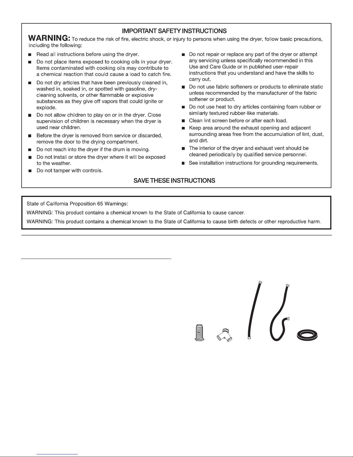
Tools and Parts
Gather the required tools and parts before starting installation. Read
and follow the instructions provided with any tools listed here.
Parts supplied:
Remove parts package from dryer drum. Check that all parts were
included.
■ Flat-blade screwdriver
■ #2 Phillips screwdriver
■ Adjustable wrench that
opens to 1" (25 mm) or hexhead socket wrench (for
adjusting dryer feet)
■ Wire stripper (direct wire
installations)
■ Tin snips (new vent
installations)
■ Level
■ Vent clamps
■ Caulking gun and compound
(for installing new exhaust
vent)
■ Tap e me asu re
4
A
B
C
A. Leveling legs (4)
B. “Y” connector
C. Short inlet hose
D. Long inlet hose
E. Rubber washer
D
E
Parts needed:
Check local codes. Check existing electrical supply and venting and
see “Electrical Requirements” and “Venting Requirements” before
purchasing parts.
Mobile home installations require
available for purchase from the dealer from whom you purchased
your dryer. For information on ordering, please refer to the
“Assistance or Service” section. You may also contact the dealer
from whom you purchased your dryer.
If using a power supply cord:
Use a UL listed power supply cord kit marked for use with clothes
yers. The kit should contain:
dr
■ A UL listed 30-amp power supply cord, rated 120/240 volt
minimum. The cord should be type SRD or SRDT and be at least
4 ft (1.22 m) long. The wires that connect to the dryer must end
in ring terminals or spade terminals with upturned ends.
■ A UL listed strain relief.
metal exhaust system hardware
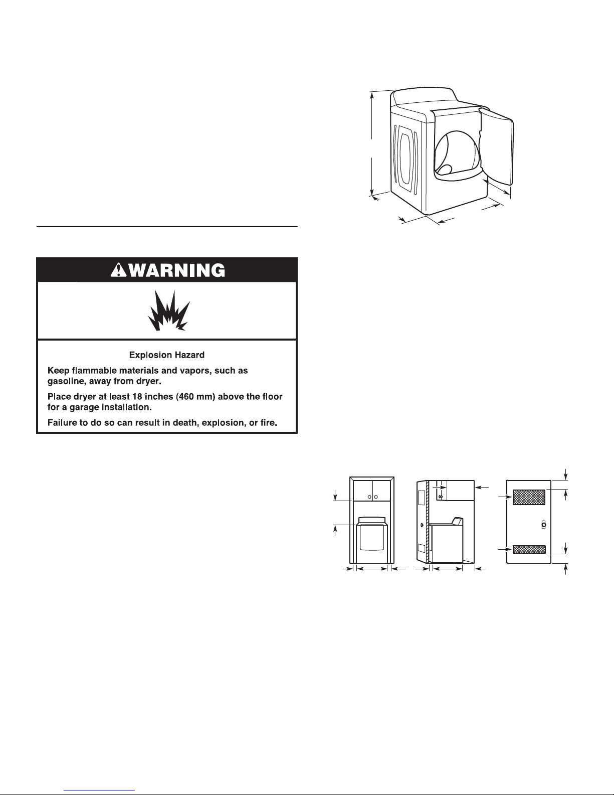
Installation Clearances
The location must be large enough to allow the dryer door to open
fully.
Dryer Dimensions
1
43
/2"
(1105 mm)
1
/4"
1
29
/4"
(743 mm)
29"
(737 mm)
22
(565 mm)
Location Requirements
You will need
■ A location that allows for proper exhaust installation. See
“Venting Requirements.”
■ A separate 30-amp circuit.
■ If you are using a power supply cord, a grounded electrical
outlet located within 2 ft (610 mm) of either side of the dryer.
See “Electrical Requirements.”
■ A sturdy floor to support the total weight (dryer and load) of
200 lbs (90.7 kg). The combined weight of a companion
nce should also be considered.
applia
■ Cold water faucets located within 4 ft (1.2 m) of the water fill
valves, and water pressure of 20-100 psi (138-690 kPa). You
may use the water supply for your washer using the “Y”
connector and short hose (if needed) which are provided.
■ 20-100 psi (138-690 kPa) for best performance.
■ A level floor with a maximum slope of 1" (25 mm) under entire
dryer.
Do not operate your dryer at temperatur
lower temperatures, the dryer might not shut off at the end of an
automatic cycle. Drying times can be extended.
The dryer must not be installed or st
exposed to water and/or weather.
Check code requirements. Some codes limit, or
installation of the dryer in garages, closets, mobile homes, or
sleeping quarters. Contact your local building inspector.
es below 45ºF (7ºC). At
ored in an area where it will be
do not permit,
*Most installations require a minimum 5" (127 mm) clearance
behind the dryer for the exhaust vent with elbow. See “Venting
Requirements.”
Installation spacing for recessed area or closet installation
The following spacing dimensions are recommended for this dryer.
This dryer has been tested for spacing of 0" (0 mm) clearance on the
sides an
d rear. Recommended spacing should be considered for the
following reasons:
■ Additional spacing should be considered for ease of installation
and servicing.
■ Additional clearances might be required for wall, door, and floor
moldings.
■ Additional spacing should be considered on all sides of the dryer
to reduce noise transfer.
■ For closet installation, with a door, minimum ventilation openings
in the top and bottom of the door are required. Louvered doors
with equivalent ventilation openings are acceptable.
■ Companion appliance spacing should also be considered.
■ Additional spacing is required if you exhaust out the rear of the
dryer to either the right or left side.
14" máx.*
18"*
(457 mm)
1"
(25 mm)
29"
(737 mm)
A
(356 mm)
1"
(25 mm)
A. Recessed area
B. Side view - closet or confined area
C. Closet door with vents
1
/4"
29
(743 mm)
B
48 in.2*
(310 cm2)
2
24 in.
*
(155 cm2)
5"
(127 mm)
3"*
(76 mm)
3"*
(76 mm)
C
*Required spacing
Mobile home - Additional installation requirements
This dryer is suitable for mobile home installations. The installation
must conform to the Manufactured Home Construction and Safety
Standard, Title 24 CFR, Part 3280 (formerly the Federal Standard for
Mobile Home Construction and Safety, Title 24, HUD Part 280) or
Standar
d CAN/CSA-Z240 MH.
5
Mobile
■ Metal exhaust system hardware, which is available for
home installations require:
purchase from your dealer.
■ Special provisions must be made in mobile homes to
introduce outside air into the dryer. The opening (such as a
nearby window) should be at least twice as large as the dryer
exhaust opening.
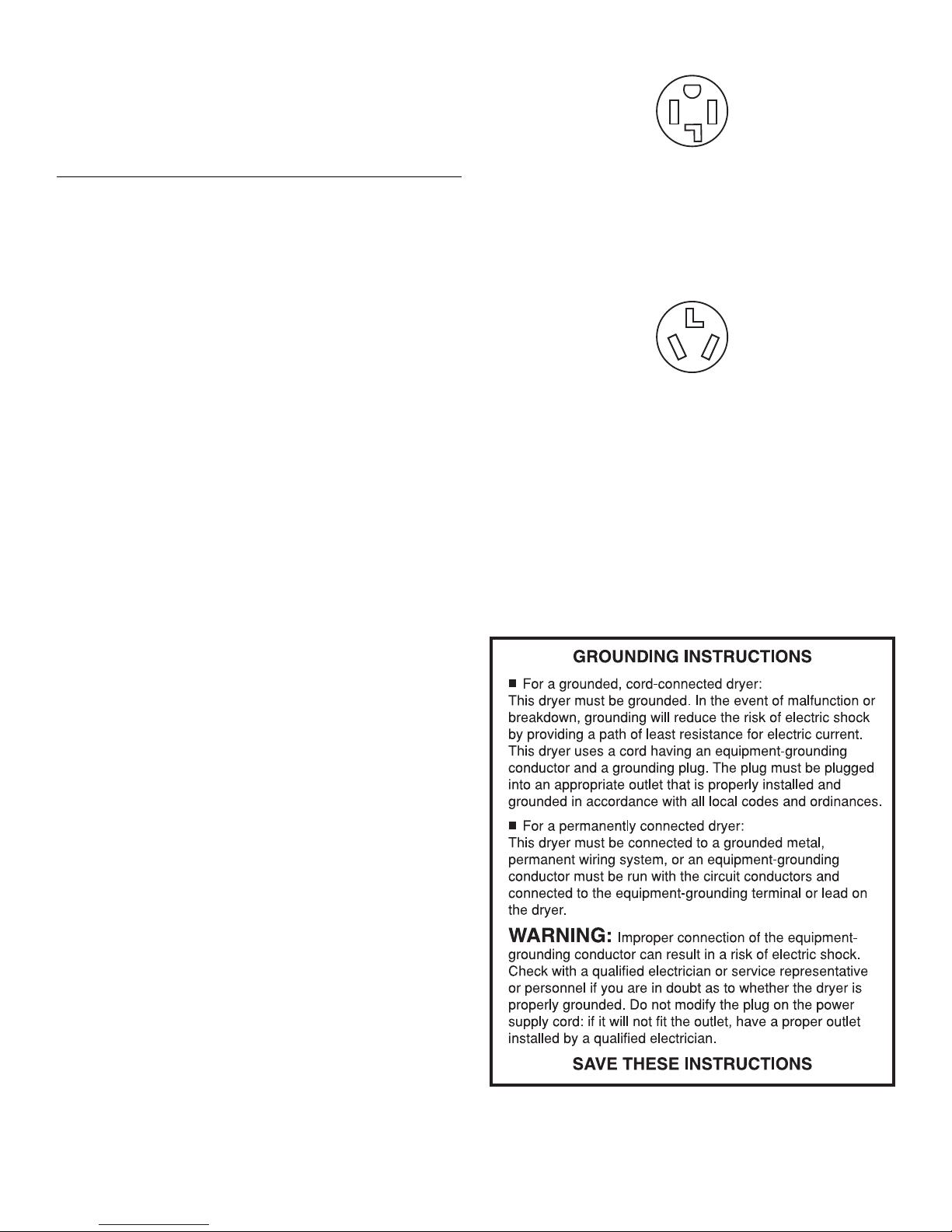
If your outlet looks like this:
4-wire receptacle (14-30R)
Electrical Requirements - U.S.A. Only
It is your responsibility
■ To contact a qualified electrical installer.
■ To be sure that the electrical connection is adequate and in
conformance with the National Electrical Code, ANSI/NFPA 70latest edition and all local codes and ordinances.
The National Electrical Code requir
connection for homes built after 1996, dryer circuits involved in
remodeling after 1996, and all mobile home installations.
A copy of the above code standards can be obtained from:
ional Fire Protection Association, One Batterymarch Park,
Nat
Quincy, MA 02269.
■ To supply the required 3 or 4 wire, single phase, 120/240 volt,
60 Hz., AC only electrical supply (or 3 or 4 wire, 120/208 volt
lectrical supply, if specified on the serial/rating plate) on a
e
separate 30-amp circuit, fused on both sides of the line. A timedelay fuse or circuit breaker is recommended. Connect to an
individual branch circuit. Do not have a fuse in the neutral or
grounding circuit.
■ Do not use an extension cord.
■ If codes permit and a separate ground wire is used, it is
recommended that a qualified electrician determine that the
ground path is adequate.
Electrical Connection
To properly install your dryer, you must determine the type of
electrical connection you will be using and follow the instructions
provided for it here.
■ This dryer is manufactured ready to install with a 3-wire electrical
supply connection. The neutral ground conductor is
permanently connected to the neutral conductor (white wire)
within the dryer. If the dryer is installed with a 4-wire electrical
supply connection, the neutral ground conductor must be
removed from the external ground connector (green screw), and
secured under the neutral terminal (center or white wire) of the
terminal block. When the neutral ground conductor is secured
under the neutral terminal (center or white wire) of the terminal
block, the dryer cabinet is isolated from the neutral conductor.
■ If local codes do not permit the connection of a neutral ground
wire to the neutral wire, see “Optional 3-wire connection” in
“Electrical Connection - U.S.A. Only” section.
■ A 4-wire power supply connection must be used when the
appliance is installed in a location where grounding through the
neutral conductor is prohibited. Grounding through the neutral is
prohibited for (1) new branch-circuit installations, (2) mobile
homes,
(3) recreational vehicles, and (4) areas where local codes
prohibit grounding through the neutral conductors.
If using a power supply cord:
Use a UL listed power supply cord kit marked for use with clothes
yers. The kit should contain:
dr
■ A UL listed 30-amp power supply cord, rated 120/240 volt
minimum. The cord should be type SRD or SRDT and be at least
4 ft (1.22 m) long. The wires that connect to the dryer must end
in ring terminals or spade terminals with upturned ends.
■ A UL listed strain relief.
es a 4-wire power supply
Then choose a 4-wire power supply cord with ring or spade
terminals and UL listed strain relief. The 4-wire power supply cord, at
least 4 ft (1.22 m) long, must have four 10-gauge copper wires and
match a 4-wire receptacle of NEMA Type 14-30R. The ground wire
(ground conductor) may be either green or bare. The neutral
conductor must be identified by a white cover.
If your outlet looks like this:
3-wire receptacle (10-30R)
Then choose a 3-wire power supply cord with ring or spade
terminals and UL listed strain relief. The 3-wire power supply cord, at
least 4 ft (1.22 m) long, must have three 10-gauge copper wires and
match a 3-wire receptacle of NEMA Type 10-30R.
If connecting by dir
Power supply cable must match power
ect wire:
supply (4-wire or 3-wire) and
be:
■ Flexible armored cable or nonmetallic sheathed copper cable
(with ground wire), protected with flexible metallic conduit. All
current-carrying wires must be insulated.
■ 10-gauge solid copper wire (do not use aluminum).
■ At least 5 ft (1.52 m) long.
6
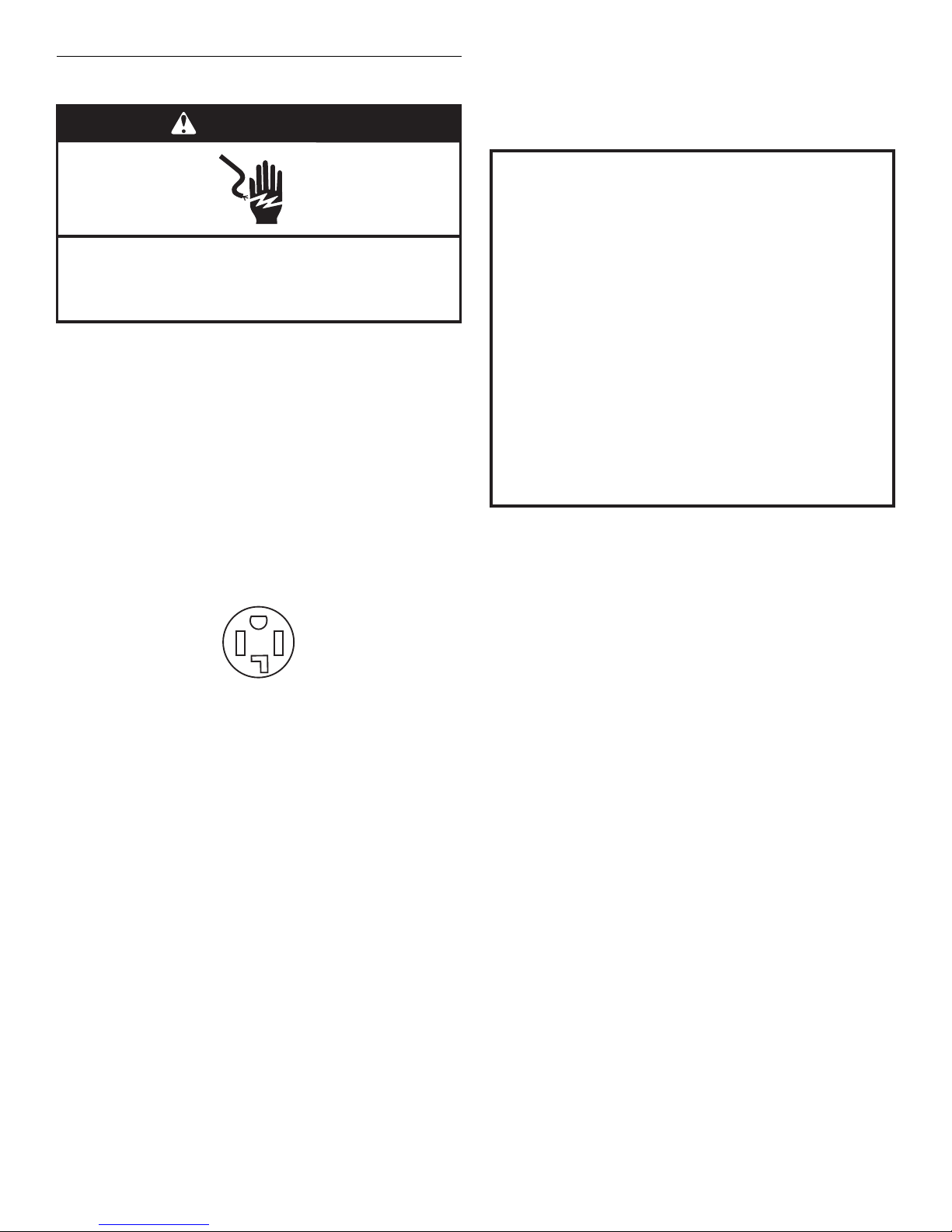
Electrical Requirements - Canada Only
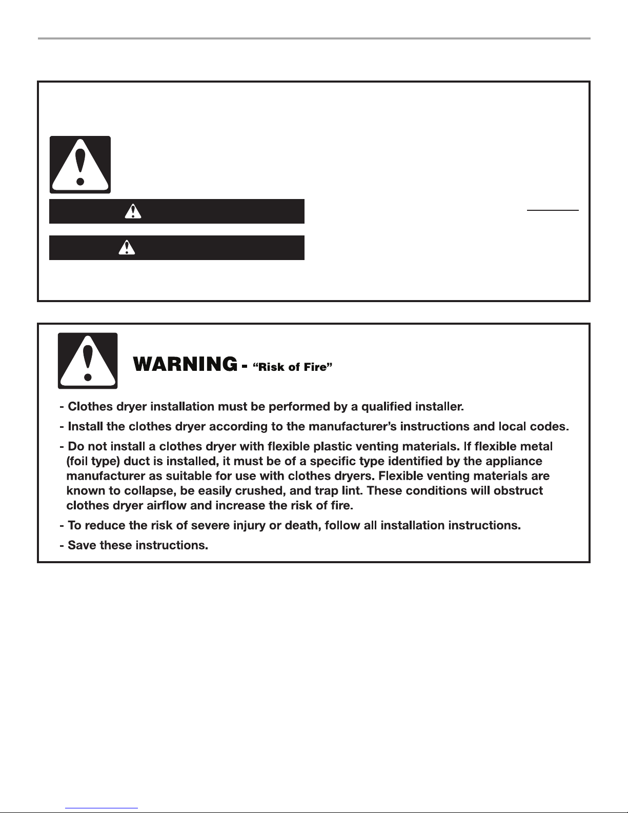
WARNING
Electrical Shock Hazard
Plug into a grounded 4 prong outlet.
Failure to do so can result in death or electrical shock.
It is your responsibility
■ To contact a qualified electrical installer.
■ To be sure that the electrical connection is adequate and in
conformance with the Canadian Electrical Code, C22.1-latest
edition and all local codes. A copy of the above codes standard
may be obtained from: Canadian Standards Association, 178
Rexdale Blvd., Toronto, ON M9W 1R3 CANADA.
■ To supply the required 4 wire, single phase, 120/240 volt, 60 Hz.,
AC only electrical supply on a separate 30-amp
both sides of the line. A time-delay fuse or circuit breaker is
recommended. Connect to an individual branch circuit.
■ This dryer is equipped with a CSA International Certified Power
Cord intended to be plugged into a standard 14-30R wall
receptacle. The cord is 5 ft (1.52 m) in length. Be sure wall
receptacle is within reach of dryer’s final location.
circuit, fused on
■ Do not use an extension cord.
If you are using a replacement power supply cord, it is
ecommended that you use Power Supply Cord Replacement Part
r
Number 3394208. For further information, please reference the
service numbers located in the “Assistance or Service” section
.
GROUNDING INSTRUCTIONS
■
For a grounded, cord-connected dryer:
This dryer must be grounded. In the event of malfunction or
breakdown, grounding will reduce the risk of electric shock
by providing a path of least resistance for electric current.
This dryer is equipped with a cord having an equipmentgrounding conductor and a grounding plug. The plug must
be plugged into an appropriate outlet that is properly
installed and grounded in accordance with all local codes
and ordinances.
WARNING: Improper connection of the equipment-
grounding conductor can result in a risk of electric shock.
Check with a qualied electrician or service representative
or personnel if you are in doubt as to whether the dryer is
properly grounded. Do not modify the plug provided with
the dryer: if it will not t the outlet, have a proper outlet
installed by a qualied electrician.
SAVE THESE INSTRUCTIONS
4-wire receptacle 14-30R
7
Electrical Connection - U.S.A. Only
E
Power Supply Cord
WARNING
Fire Hazard
Use a new UL listed 30 amp power supply cord.
Use a UL listed strain relief.
Disconnect power before making electrical connections.
Connect neutral wire (white or center wire) to center
terminal (silver).
Ground wire (green or bare wire) must be connected to
green ground connector.
Connect remaining 2 supply wires to remaining
2 terminals (gold).
Securely tighten all electrical connections.
Failure to do so can result in death, re, or
electrical shock.
Direct Wire
WARNING
Fire Hazard
Use 10 gauge solid copper wire.
Use a UL listed strain relief.
Disconnect power before making electrical connections.
Connect neutral wire (white or center wire) to center
terminal (silver).
Ground wire (green or bare wire) must be connected to
green ground connector.
Connect remaining 2 supply wires to remaining
2 terminals (gold).
Securely tighten all electrical connections.
Failure to do so can result in death, re, or
electrical shock.
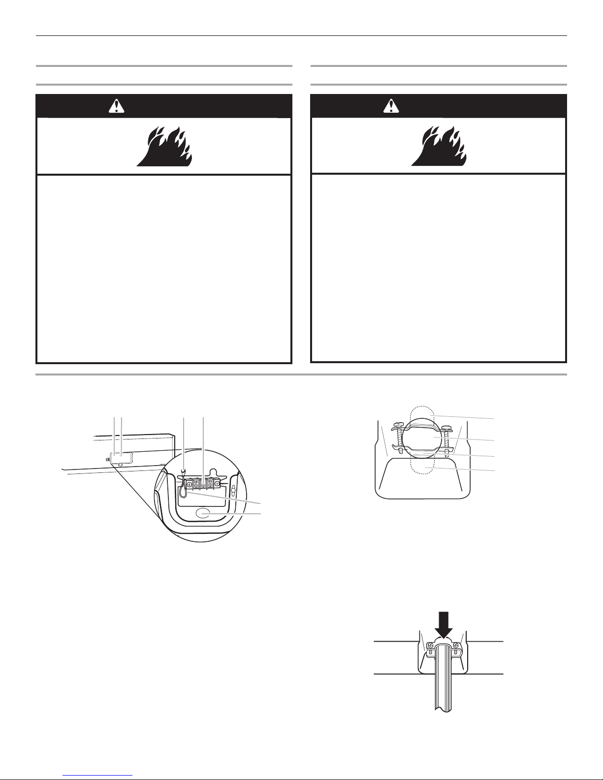
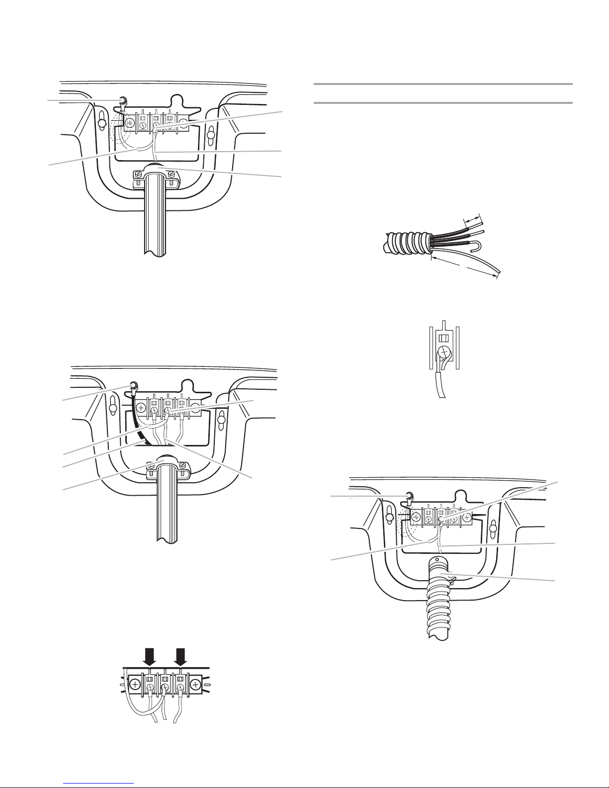
1. Disconnect power.
2. Remove the hold-down screw and terminal block cover.
B
A
A. Terminal block cover
B. Hold-down screw
C. External ground conductor screw
D. Center, silver-colored terminal block screw
E. Neutral ground wire
F. Hole below terminal block opening
3. Install strain relief.
Style 1: Power supply cord st
■ Remove the screws from a
marking on strain relief). Put the tabs of the two clamp sections
into the hole below the terminal block opening so that one tab is
pointing up and the other is pointing down, and hold in place.
rain relief
3
/4" (19 mm) UL listed strain relief (UL
D
C
Tighten strain relief screws just enough to hold the two clamp
sections together.
A
B
C
D
F
■ Put power supply cord through the strain relief. Be sure that the
wire insulation on the power supply cord is inside the strain
relief. The strain relief should have a tight fit with the dryer
cabinet and be in a horizontal position. Do not further tighten
strain relief screws at this point.
A. Strain relief tab pointing up
B. Hole below terminal block opening
C. Clamp section
D. Strain relief tab pointing down
8
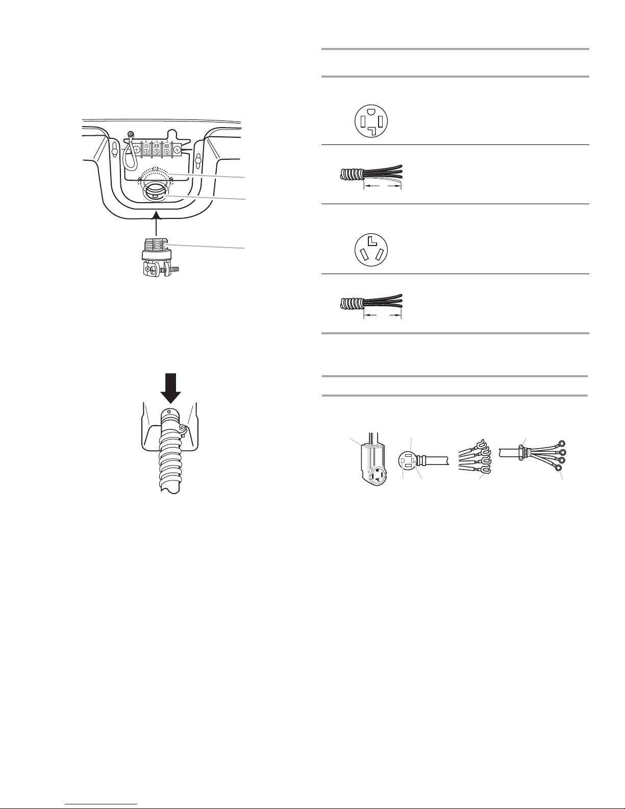
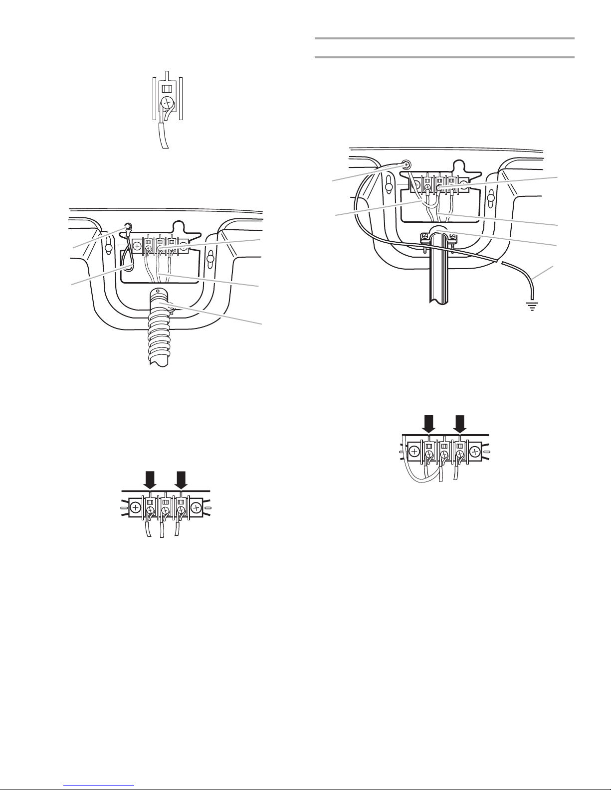
Style 2: Direct wire strain relief
A
■ Unscrew the removable conduit connector and any screws from
3
/4" (19 mm) UL listed strain relief (UL marking on strain relief).
a
Put the threaded section of the strain relief through the hole
below the terminal block opening. Reaching inside the terminal
block opening, screw the removable conduit connector onto the
strain relief threads.
Electrical Connection Options
If your home has: And you
connecting to:
4-wire receptacle
(NEMA type 14-30R)
A UL listed,
120/240-volt
minimum
30-amp, dryer
power supply
cord*
will be
,
Go to Section:
4-wire connection:
Power Supply Cord
A
B
C
A. Removable conduit connector
B. Hole below terminal block opening
C. Strain relief threads
■ Put direct wire cable through the strain relief. The strain relief
should have a tight fit with the dryer cabinet and be in a
horizontal position. Tighten strain relief screw against the direct
wire cable.
4-wire direct
5"
(127 mm)
3-wire receptacle
(NEMA type 10-30R)
A fused
disconnect or
circuit breaker
box*
A UL listed,
120/240-volt
minimum
,
4-wire connection:
Direct Wire
3-wire connection:
Power Supply Cord
30-amp, dryer
power supply
cor
d*
3-wire direct
3½"
(89 mm)
A fused
disconnect or
circuit breaker
box*
3-wire connection:
Direct Wire
*If local codes do not permit the connection of a cabinet-ground
ctor to the neutral wire, go to “Optional 3-wire
condu
connection” section.
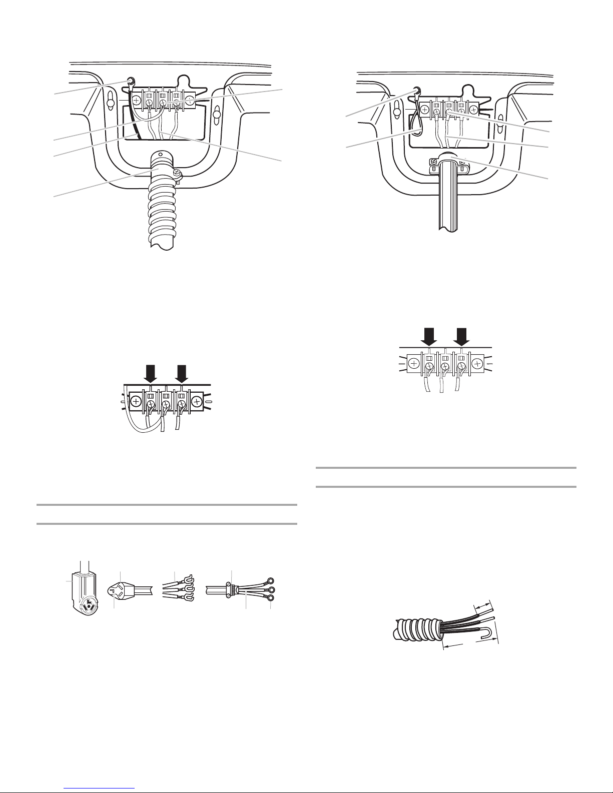
4-wire connection: Power supply cord
IMPORTANT: A 4-wire connection is required for mobile homes and
where local codes do not permit the use of 3-wire connections.
BF
E
G
4. Now complete installation following instructions for your type of
electrical connection:
4-wire (r
3-wire (if 4-wir
ecommended)
e is not available)
C
D
A. 4-wire receptacle (NEMA type 14-30R)
B. 4-prong plug
C. Ground prong
D. Neutral prong
E. Spade terminals with upturned ends
3
/4" (19 mm) UL listed strain relief
F.
G. Ring terminals
1. Remove center, silver-colored terminal block screw.
9
2. Remove neutral ground wire from external ground conductor
A
A
A
screw. Connect neutral ground wire and the neutral wire (white or
center wire) of power supply cord under center, silver-colored
terminal block screw. Tighten screw.
6. Insert tab of terminal block cover into slot of dryer rear panel.
Secure cover with hold-down screw.
ou have completed your electrical connection. Now go to
7. Y
“Venting Requirements.”
B
A. Neutral ground wire
B. External ground conductor screw - Dotted line shows position
UTRAL ground wire before being moved to center, silver-
of NE
colored terminal block screw.
C. Center, silver-colored terminal block screw
D. Neutral wire (white or center wire)
3
/4" (19 mm) UL listed strain relief
E.
3. Connect ground wire (green or bare) of power supply cord to
external ground conductor screw. Tighten screw.
4-wire connection: Direct Wire
C
IMPORTANT: A 4-wire connection is required for mobile homes and
where local codes do not permit the use of 3 wire connections.
Direct wire cable must have 5 ft (1.52 m) of extra length so dryer can
be moved
D
Strip 5" (127 mm) of outer covering f
ground wire at 5" (127 mm). Cut 1
E
wires. Strip insulation back 1" (25 mm). Shape ends of wires into a
hook shape.
When connecting to the terminal block, place the hooked end of the
wire under the screw of the terminal block (hook facing right),
squeeze hooked end together and tighten screw, as shown.
if needed.
rom end of cable, leaving bare
1
/2" (38 mm) from 3 remaining
1"
(25 mm)
5"
(127 mm)
E
1. Remove center
2. Remove neut
, silver-colored terminal block screw.
ral ground wire from external ground conductor
screw. Connect neutral ground wire and place the hooked end
(hook facing right) of the neutral wire (white or center wire) of direct
B
C
F
D
wire cable under the center screw of the terminal block. Squeeze
hooked ends together. Tighten screw.
B
C
D
A. External ground conductor screw
B. Neutral ground wire
C. Ground wire (green or bare) of power supply cord
D. ¾" (19 mm) UL listed strain relief
E. Center, silver-colored terminal block screw
F. Neutral wire (white or center wire)
E
4. Connect the other wires to outer terminal block screws. Tighten
screws.
A. Neutral ground wire
B. External ground conductor screw -
position of NEUTRAL ground wire before being moved to
center, silver-colored terminal block screw.
C. Center, silver-colored terminal block screw
D. Neutral wire (white or center wire)
E. ¾" (19 mm) UL listed str
ain relief
Dotted line shows
5. Tighten strain relief screws.
10
3. Connect ground wire (green or bare) of direct wire cable to
A
E
A
external ground conductor screw. Tighten screw.
B
C
F
D
A. External ground conductor screw
B. Neutral ground wire
C. Ground wire (green or bare) of power supply cord
D. ¾" (19 mm) UL listed strain relief
E. Center, silver-colored terminal block screw
F. Neutral wire (white or center wire)
4. Place the hooked ends of the other direct wire cable wires under
the outer terminal block screws (hooks facing right). Squeeze
hooked ends together. Tighten screws.
2. Connect neutral wire (white or center wire) of power supply cord
to the center, silver-colored terminal screw of the terminal block.
Tighten screw.
A
C
B
D
E
A. External ground conductor screw
B. Neutral ground wire
C. Center, silver-colored terminal block screw
D. Neutral wire (white or center wire)
E. ¾" (19 mm) UL listed str
ain relief
3. Connect the other wires to outer terminal block screws. Tighten
screws.
4. Tighten strain relief screws.
5. Insert tab of terminal block cover into slot of dryer rear panel.
Secure cover with hold-down screw.
5. Tighten strain relief screw.
6. Inser
t tab of terminal block cover into slot of dryer rear panel.
6. You have completed your electrical connection. Now go to
“Venting Requirements.”
Secure cover with hold-down screw.
7. Y
ou have completed your electrical connection. Now go to
“Venting Requirements.”
3-wire connection: Power supply cord
Use where local codes permit connecting cabinet-ground
conductor to neutral wire.
3-wire connection: Direct Wire
Use where local codes permit connecting cabinet-ground
conductor to neutral wire.
Direct wire cable must have 5 ft (1.52 m) of extra length so dryer can
be moved if needed.
1
/2" (89 mm) of outer covering from end of cable. Strip
Strip 3
insulation back 1" (25 mm). If using 3-wire cable with ground wire,
B
C
A. 3-wire receptacle (NEMA type 10-30R)
B. 3-wire plug
C. Neutral prong
D. Spade terminals with upturned ends
3
/4" (19 mm) UL listed strain relief
E.
F. Ri ng te rm i na ls
G. Neutral wire (white or center wire)
D
E
F
G
cut bare wire even with outer covering. Shape ends of wires into a
hook shape.
1"
(25 mm)
3½"
(89 mm)
1. Loosen or remove center, silver-colored terminal block screw.
11
When connecting to the terminal block, place the hooked end of the
wire under the screw of the terminal block (hook facing right),
squeeze hooked end together and tighten screw, as shown.
1. Loosen or remove center, silver-colored terminal block screw.
2. Place the hooked end of the neutral wire (white or center wire) of
direct wire cable under the center screw of terminal block (hook
facing right). Squeeze hooked end together. Tighten screw.
Optional 3-wire connection
Use for direct wire or power supply cord where local codes do
not permit connecting cabinet-ground conductor to neutral wire.
1. Remove center
2. Remove neut
screw. Connect neutral ground wire and the neutral wire (white or
center wire) of power supply cord/cable under center, silvercolored terminal block screw. Tighten screw.
A
, silver-colored terminal block screw.
ral ground wire from external ground conductor
C
A
C
B
D
E
A. External ground conductor screw
B. Neutral ground wire
C. Center, silver-colored terminal block screw
D. Neutral wire (white or center wire)
3
/4" (19 mm) UL listed strain relief
E.
3. Place the hooked ends of the other direct wire cable wires under
the outer terminal block screws (hooks facing right). Squeeze
hooked ends together. Tighten screws.
4. Tighten strain relief screw.
5. Insert tab of terminal block cover into slot of dryer rear panel.
Secure cover with hold-down screw.
6. You have completed your electrical connection. Now go to
“Venting Requirements.”
B
D
E
F
A. External ground conductor screw
B. Neutral ground wire
C. Center, silver-colored terminal block screw
D. Neutral wire (white or center wire)
3
/4" (19 mm) UL listed strain relief
E.
F. Grounding path determined by a qualified electrician
3. Connect the other wires to outer terminal block screws. Tighten
screws.
4. Tighten strain relief screws.
nsert tab of terminal block cover into slot of dryer rear panel.
5. I
Secure cover with hold-down screw.
6. Connect a separate copper ground wire from the external ground
conductor screw to an adequate ground.
12
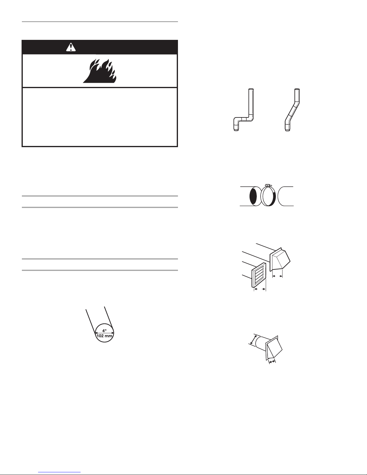
Venting Requirements
WARNING
Fire Hazard
Use a heavy metal vent.
Do not use a plastic vent.
Do not use a metal foil vent.
Failure to follow these instructions can result in death
or re.
WARNING: To reduce the risk of fire, this dryer MUST BE
EXHAUSTED OUTDOORS.
IMPORTANT: Observe all governing codes and ordinances.
The dryer exhaust must not be connected into any gas vent,
chimney, wall, ceiling, attic, crawlspace, or a concealed space of a
building.
■ Remove excess flexible metal vent to avoid sagging and kinking
that may result in reduced airflow and poor performance.
■ Do not install flexible metal vent in enclosed walls, ceilings, or
floors.
■ The total length of flexible metal duct shall not exceed 7
3
/4 ft
(2.4 m).
Elbows
45° elbows provide better airflow than 90° elbows.
Good Better
Clamps
■ Use clamps to seal all joints.
■ Exhaust vent must not be connected or secured with screws or
other fastening devices that extend into the interior of the duct
and catch lint. Do not use duct tape.
If using an existing vent system
■ Clean lint from the entire length of the system and make sure
exhaust hood is not plugged with lint.
■ Replace any plastic or metal foil vent with rigid heavy metal or
flexible metal vent.
■ Review Vent system chart. Modify existing vent system if
necessary to achieve the best drying performance.
If this is a new vent system
Vent material
■ Use a heavy metal vent. Do not use plastic or metal foil vent.
■ 4" (102 mm) heavy metal exhaust vent and clamps must be
used. DURASAFE™ venting products are recommended.
4" (102 mm) heavy metal exhaust vent
DURASAFE™ vent products can be purchased from your dealer
or by calling Whirlpool Parts and Accessories. For more
information, see the “Assistance or Service” section.
Rigid metal
■ For best drying performance, rigid metal vents are
recommended.
■ Rigid metal vent is recommended to avoid crushing and kinking.
Flexible met
■ Flexible metal vents are acceptable only if accessible for
cleaning.
■ Flexible metal vent must be fully extended and supported when
the dryer is in its final location.
vent
al vent
Clamp
Exhaust
Recommended hood styles are shown here.
B
A
4"
(102 mm)
4"
(102 mm)
A. Louvered hood style
B. Box hood style
The angled hood style (shown here) is acceptable.
4"
(102 mm)
■ An exhaust hood should cap the vent to keep rodents and
C
2½"
(64 mm)
insects from entering the home.
■ Exhaust hood must be at least 12" (305 mm) from the ground or
any object that may be in the path of the exhaust (such as
flowers, rocks, or bushes, snow line, etc.).
13
■ Do not use an exhaust hood with a magnetic latch.
A
Improper venting can cause moisture and lint to collect
indoors, which may result in:
Moisture damage to woodwork, furniture, paint, wallpaper,
carpets, etc.
Housecleaning problems and health problems.
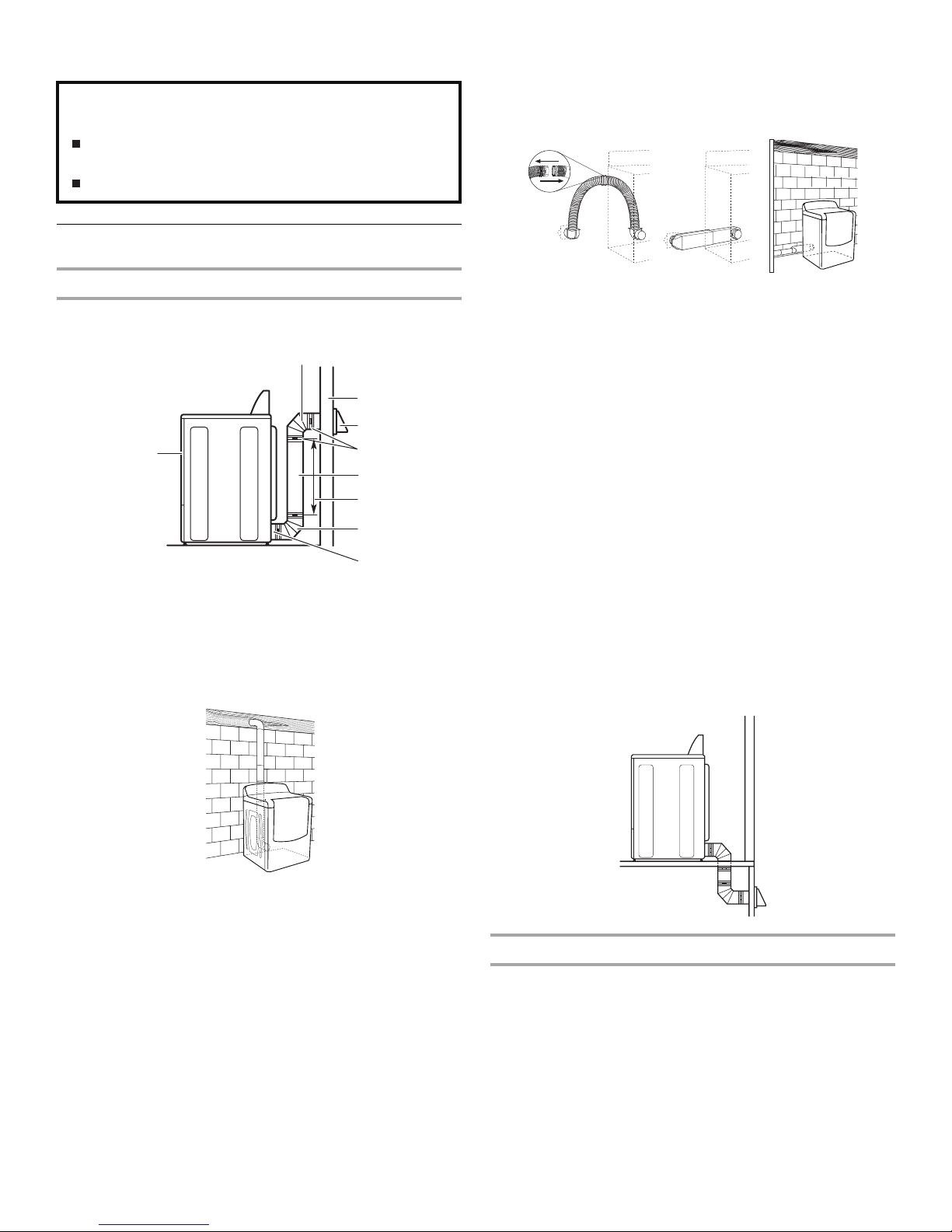
Plan Vent System
Alternate installations for close clearances
Venting systems come in many varieties. Select the type best for
your installation. Two close-clearance installations are shown. Refer
to the manufacturer’s instructions.
Choose your exhaust installation type
Recommended exhaust installations
Typical installations vent the dryer from the rear of the dryer.
B
C
D
E
F
G
B
H
A. Dryer
B. Elbow
C. Wall
D. Exhaust hood
E. Clamps
F. Rigid metal or flexible metal vent
G. Vent length necessar
H. Exhaust outlet
y to connect elbows
Standard exhaust installation with rigid metal or flexible
metal vent
A
A. Over-the-top installation (also available with one offset elbow)
B. Periscope installation
C. Rear exhaust installation
to left or right side
B
C
NOTE: The following kits for close clearance alternate installations
are available for purchase. Please see the “Assistance or Service”
section to order.
■ Over-the-Top Installation:
Part Number 4396028
■ Periscope Installation (For use with dryer vent to wall vent
mismatch):
Part Number 4396037 - 0" (0 mm) to 18" (457 mm) mismatch
Part Number 4396011 - 18" (457 mm) to 29" (737 mm)
mismatch
Part Number 4396014 - 29" (737 mm) to 50" (127 mm)
mismatch
■ Rear exhaust installation to left or right side:
Part Number 49611
Special provisions for mobil
e home installations
The exhaust vent must be securely fastened to a noncombustible
portion of the m
obile home structure and must not terminate
beneath the mobile home. Terminate the exhaust vent outside.
14
Determine vent path
■ Select the route that will provide the straightest and most direct
path outdoors.
■ Plan the installation to use the fewest number of elbows and
turns.
■ When using elbows or making turns, allow as much room as
possible.
■ Bend vent gradually to avoid kinking.
■ Use the fewest 90° turns possible.
Determine vent length and elbows needed for best
drying performance
■ Use the following Vent system chart to determine type of vent
material and hood combinations acceptable to use.
NOTE: D
Vent system chart. Exhaust systems longer than those specified
will:
■ Shorten the life of the dryer.
■ Reduce performance, resulting in longer drying times and
The Vent system chart provides venting r
to achieve the best drying performance.
o not use vent runs longer than those specified in the
increased energy usage.
equirements that will help
Vent system chart
NOTE: Performance of rear exhaust to either side of the dryer is
equivalent to adding one elbow. To determine maximum exhaust
length, add one elbow to the chart.
Number of
90º turns
or elbows
0 Rigid meta
1 Rigid meta
2 Rigid meta
3 Rigid meta
4 Rigid meta
Type of
ven
Box or
t
l 64 ft (20 m) 58 ft (17.7 m)
l 54 ft (16.5 m) 48 ft (14.6 m)
l 44 ft (13.4 m) 38 ft (11.6 m)
l 35 ft (10.7 m) 29 ft (8.8 m)
l 27 ft (8.2 m) 21 ft (6.4 m)
Louvered
hoods
Angled
hoods
Install Vent System
1. Install exhaust hood. Use caulking compound to seal exterior wall
opening around exhaust hood.
onnect vent to exhaust hood. Vent must fit inside exhaust hood.
2. C
Secure vent to exhaust hood with 4" (102 mm) clamp.
3. Run
vent to dryer location. Use the straightest path possible. See
“Determine vent path” in “Plan Vent System.” Avoid 90º turns.
Use clamps to seal all joints. Do not use duct tape, screws, or
other fastening devices that extend into the interior of the vent to
secure vent, because they can catch lint.
3. Examine the leveling legs. Find the diamond marking.
4. Screw the legs into the leg holes by hand. Use a wrench to finish
turning the legs until the diamond marking is no longer visible.
5. Place a carton cor
the 2 dryer back corners. Stand the dryer up. Slide the dryer on
the corner posts until it is close to its final location. Leave enough
room to connect the exhaust vent.
ner post from dryer packaging under each of
Connect Vent
1. Using a 4" (102 mm) clamp, connect vent to exhaust outlet in
dryer. If connecting to existing vent, make sure the vent is clean.
The dryer vent must fit over the dryer exhaust outlet and inside the
exhaust hood. Check that the vent is secured to exhaust hood
with a 4" (102 mm) clamp.
ve dryer into its final location. Do not crush or kink vent.
2. Mo
3. Once the exha
posts and cardboard.
ust vent connection is made, remove the corner
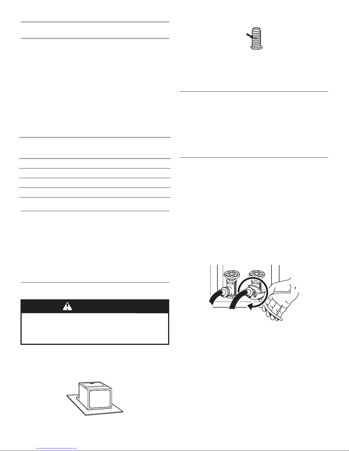
Connect Inlet Hose
The dryer must be connected to the cold water faucet using the new
inlet hoses. Do not use old hoses.
1. T
urn cold water faucet off and remove washer inlet hose.
2. Remove old rubber wash
rubber washer provided. If space permits, attach the brass female
end of the “Y” connector to the cold water faucet.
If “Y” connector can be attached directly to cold water
NOTE:
faucet, go to Step 6. If “Y” connector cannot be attached
directly to the cold water faucet, the short hose must be used.
Continue with Step 3.
3. Attach short hose to cold water faucet. Screw on coupling by
hand until it is seated on faucet.
4. Using
pliers, tighten the couplings with an additional two-thirds
turn.
er from inlet hose and replace with new
Install Leveling Legs
WARNING
Excessive Weight Hazard
Use two or more people to move and install dryer.
Failure to do so can result in back or other injury.
1. To avoid damaging the floor, use a large, flat piece of cardboard
from the dryer carton. Place cardboard under the entire back
edge of the dryer.
2. Fi
rmly grasp the body of the dryer (not the top or console panel).
Gently lay the dryer on the cardboard. See illustration.
Do not overtighten. Damage to the coupling can result.
NOTE:
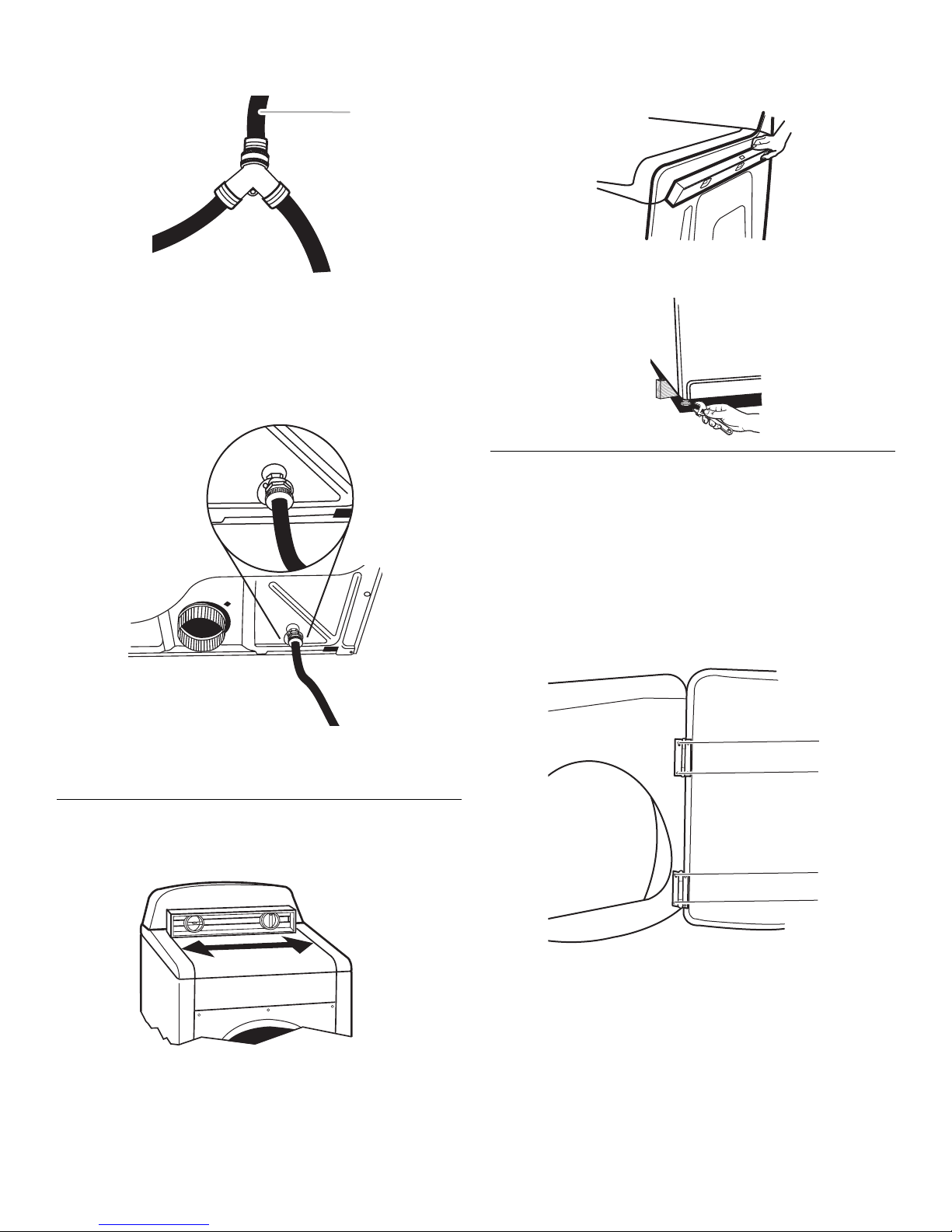
5. Attach “Y” connector
coupling by hand until it is seated on connector.
6. One end of th
coupling. Attach this end to the “Y” connector.
7. Attach washer cold inlet hose to ot
Screw on coupling by hand until it is seated on connector.
e long hose has a wire mesh strainer inside the
to brass male end of small hose. Screw on
her end of “Y” connector.
15
8. Using pliers, tighten the couplings with an additional two-thirds
turn.
A
A. Inlet to cold water
NOTE: Do not overtighten. Damage to the coupling can result.
9. Attach
10. U
other end of long hose to fill valve at bottom of dryer back
panel. Screw on coupling by hand until it is seated on fill valve
connector.
sing pliers, tighten the coupling with an additional two-thirds
turn.
Then, by placing a level in the crease on the side of the dryer
be
tween the top of the dryer and the dryer cabinet, check the
levelness from front to back.
If the dryer is not level, prop up the dryer using a wood block. Use a
wrench to adjust the legs up or down and check again for levelness.
Reverse Door Swing
You can change your door swing from a right-side opening to a leftside opening, if desired.
1. Place a towel or soft cloth on top of the dryer or work space to
avoid damaging the surface.
Remove the door assembly
1. Open
2. Remove the bottom scr
3. Loosen th
the dryer door.
ew from each of the 2 hinges that attach
the dryer door to the front panel of the dryer.
e top screw from each of the 2 hinges in Step 2.
NOTE: Do not overtighten. Damage to the coupling can result.
11. Check that the water faucets ar
12. Check for leaks ar
ound “Y” connector, faucet, and hoses.
e on.
Level Dryer
Check the levelness of the dryer by first placing a level on the top of
the dryer near the console.
A
B
A
B
A. Loosen these screws.
B. Remove these screws.
4. Remove the dryer door and the hinges by lifting upward on the
door. Lay the door on a flat, protected surface, with the inside of
the door facing up. Remove remaining 2 loose screws from dryer
fr
ont panel.
16
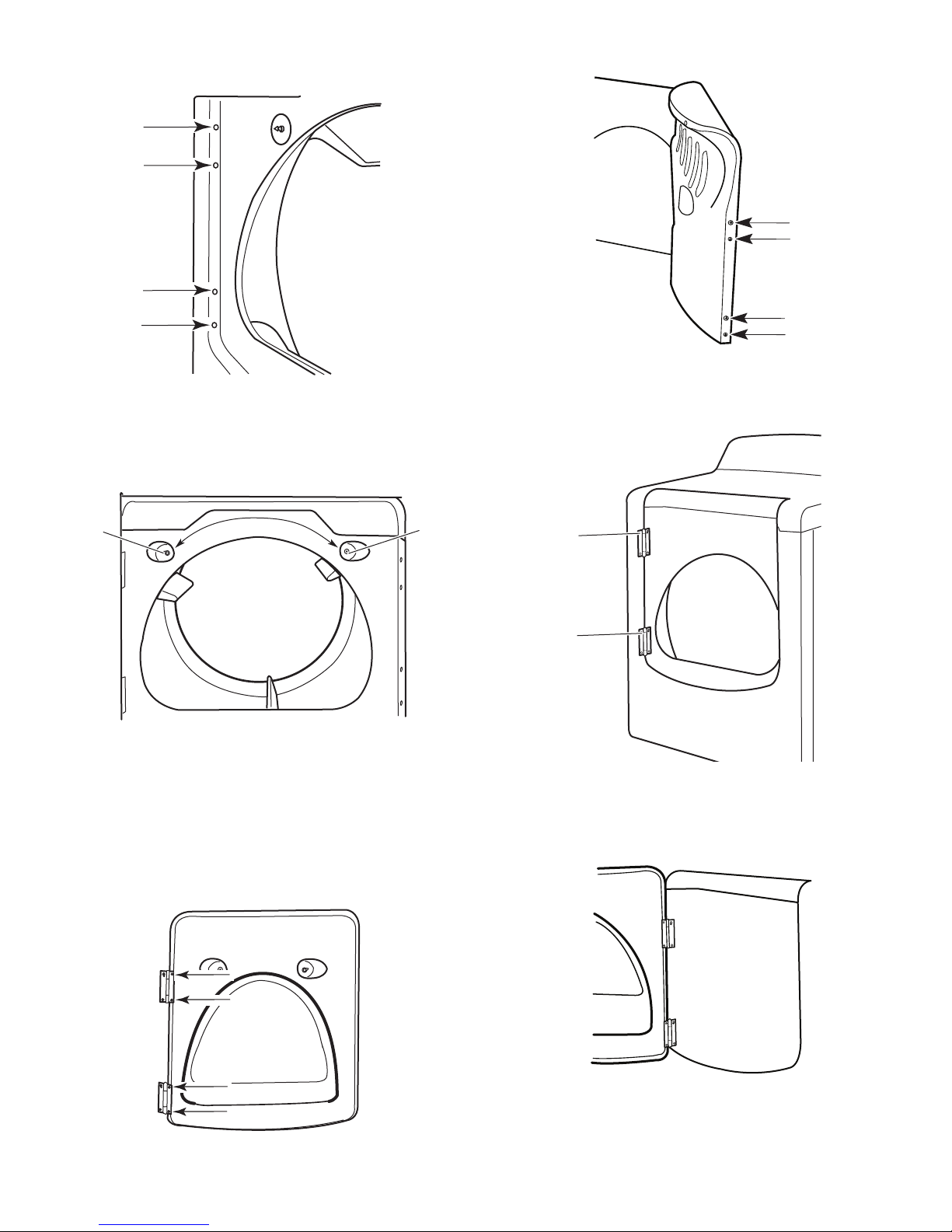
5. Remove the 4 plastic plugs located outside the dryer door
A
A
opening.
6. Install 4 plastic plugs into screw holes in the dryer left where the
hinges were removed in Step 4.
Reverse the strike
1. Remove the door strike from the dryer door opening.
2. Remo
ve the cosmetic screw opposite the door strike.
3. Remove the 4 screws from the opposite side of the door.
4. Install the 2 hinges to the front panel of the dryer using 4 screws.
Use the non-slotted side to attach the hinge to the front panel.
5. Install scr
ews in the top hinge holes in the door. Do not tighten
screws. Leave approximately ¼" (5 mm) of screw exposed.
B
A. Door strike
B. Cosmetic screw
3. Reinstall the door strike and cosmetic screw on the opposite side
of the dryer door opening from where they were removed.
NOTE: Do
or strike and plugs must be on the same side of the
dryer door opening.
Reinstall the door
1. Remove the
4 screws and 2 hinges from the dryer door.
2. Replace the 4 screws in the same holes.
A
A. Install these screws first.
6. Hang door by placing screw heads into top slotted holes of
hinges and slide door down. Align bottom screw holes in hinge
and door. Install two bottom screws. Tighten all hinge screws.
7. Close door to engage door strike.
17
 Loading...