


CABRIO W10150626
Whirlpool CABRIO W10150626, CABRIO WGD6200SW2, CABRIO WGD6400SG2, CABRIO WGD6400SW2, CABRIO WGD6400SB2 Use And Care Manual
cabrlo
FABRIC CARE SYSTEM
SYSTEME DE SOIN DES TISSUS
CABRIOTMFABRIC
CARESYSTEMGAS
DRYER
W _ _"!
For questions about features, operation/performance,
parts, accessories or service call: 1-800-253-1301
In Canada, call: 1-800-807-6777
www.whirlpool.com or www.whirlpool.ca
p Ik
SECHEUSEA GAZ
CABRIOTMAVEC
SYSTEMEDESOINDES
or visit our website at
TISSUS
W10150626A
Au Canada, pour assistance, installation ou service, composez le :
Para obtener acceso al Manual de uso y cuidado en
espafiol, o para obtener informacion adicional acerca
de su producto, visite: www.whirlpool.com.
Tenga listo su nQmero de modelo completo. Puede
encontrar el nQmero de modelo y de serie dentro de la
cavidad superior de la puerta.
Table of Contents/Table des matieres ................. 2
1-800-807-6777
ou visitez notre site internet h
www.whirlpool.ca
TABLEOFCONTENTS
TABLEDESMATIERES
DRYER SAFETY .............................................................................. 3
INSTALLATION INSTRUCTIONS .................................................. 5
Tools and Parts ............................................................................ 5
Location Requirements ............................................................... 5
Electrical Requirements ............................................................... 6
Gas Supply Requirements ........................................................... 7
Venting Requirements .................................................................. 8
Plan Vent System ......................................................................... 9
Install Vent System ..................................................................... 10
Install Leveling Legs ................................................................... 10
Make Gas Connection ............................................................... 11
Connect Vent .............................................................................. 11
Level Dryer ................................................................................. 11
Reverse Door Swing .................................................................. 12
Complete Installation ................................................................. 13
DRYER USE .................................................................................. 14
Starting Your Dryer ..................................................................... 14
Stopping, Pausing or Restarting ................................................ 15
Drying and Cycle Tips ................................................................ 15
Status Lights .............................................................................. 15
Cycles ......................................................................................... 16
Modifiers ..................................................................................... 17
Options ....................................................................................... 17
End of Cycle Signal .................................................................... 18
Changing Cycles, Modifiers and Options .................................. 18
Drying Rack Option .................................................................... 18
DRYER CARE ............................................................................... 19
Cleaning the Dryer Location ...................................................... 19
Cleaning the Lint Screen ............................................................ 19
Cleaning the Dryer Interior ......................................................... 19
Removing Accumulated Lint ...................................................... 19
Vacation and Moving Care ......................................................... 20
Changing the Drum Light ........................................................... 20
TROUBLESHOOTING .................................................................. 20
ASSISTANCE OR SERVICE ......................................................... 22
ACC ESSO R IES............................................................................. 22
WARRANTY .................................................................................. 23
SI_CURITI_ DE LA SI_CHEUSE .................................................... 24
INSTRUCTIONS D'INSTALLATION ............................................. 26
Outillage et pieces ...................................................................... 26
Exigences d'emplacement ......................................................... 26
Specifications electriques .......................................................... 27
Alimentation en gaz .................................................................... 28
Exigences concernant I'evacuation ........................................... 29
Planification du systeme d'evacuation ...................................... 30
Installation du systeme d'evacuation ......................................... 32
Installation des pieds de nivellement ......................................... 32
Raccordement au gaz ................................................................ 32
Raccordement du conduit d'evacuation ................................... 33
Reglage de I'aplomb de la secheuse ......................................... 33
Inversion du sens d'ouverture de la porte ................................. 33
Achever I'installation .................................................................. 35
UTILISATION DE LA SI_CHEUSE ................................................ 36
Mise en marche de la secheuse ................................................ 36
Arr_t, pause ou remise en marche ............................................. 37
Conseils pour le sechage et les programmes ........................... 37
T6moins lumineux ...................................................................... 38
Programmes ............................................................................... 38
Modificateurs .............................................................................. 39
Options ....................................................................................... 40
Signal de fin de programme ....................................................... 40
Changement des programmes, modificateurs et options .........41
Option de grille de sechage ....................................................... 41
ENTRETIEN DE LA SI_CI-IEUSE .................................................. 42
Nettoyage de I'emplacement de la secheuse ........................... 42
Nettoyage du filtre a charpie ...................................................... 42
Nettoyage de I'interieur de la secheuse ..................................... 43
Retrait de la charpie accumulee ................................................ 43
Precautions & prendre pour les vacances et avant un
dem6nagement .......................................................................... 43
Changement de I'ampoule d'eclairage du tambour .................. 43
DI_PAN NAGE................................................................................. 44
ASSISTANCE OU SERVICE ......................................................... 46
ACCESSOIRES ............................................................................. 46
GARANTIE ..................................................................................... 47
2
DRYERSAFETY
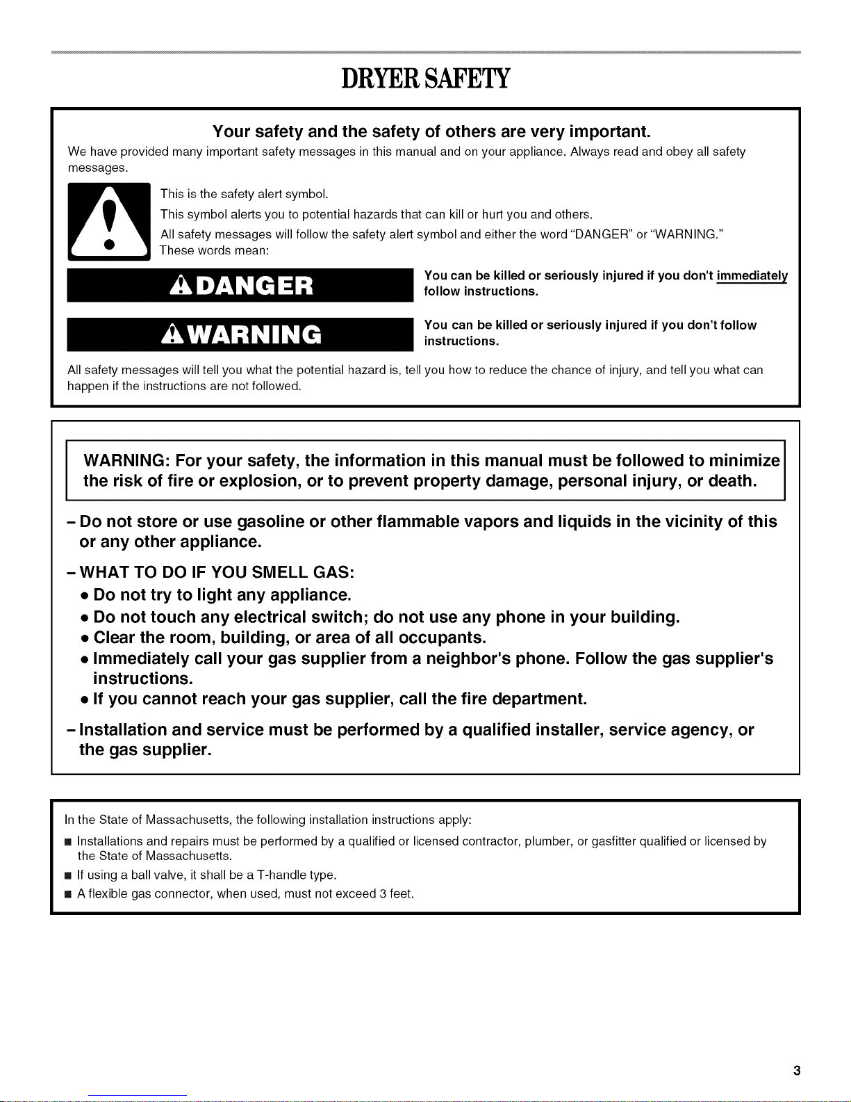
Your safety and the safety of others are very important.
We have provided many important safety messages in this manual and on your appliance. Always read and obey all safety
messages.
This is the safety alert symbol.
This symbol alerts you to potential hazards that can kill or hurt you and others.
All safety messages will follow the safety alert symbol and either the word "DANGER" or "WARNING."
These words mean:
You can be killed or seriously injured if you don't immediately
follow instructions.
You can be killed or seriously injured if you don't follow
instructions.
All safety messages will tell you what the potential hazard is, tell you how to reduce the chance of injury, and tell you what can
happen if the instructions are not followed.
WARNING: For your safety, the information in this manual must be followed to minimize
the risk of fire or explosion, or to prevent property damage, personal injury, or death,
- Do not store or use gasoline or other flammable vapors and liquids in the vicinity of this
or any other appliance.
- WHAT TO DO IF YOU SMELL GAS:
• Do not try to light any appliance.
• Do not touch any electrical switch; do not use any phone in your building.
• Clear the room, building, or area of all occupants.
• Immediately call your gas supplier from a neighbor's phone. Follow the gas supplier's
instructions.
• If you cannot reach your gas supplier, call the fire department.
- Installation and service must be performed by a qualified installer, service agency, or
the gas supplier,
In the State of Massachusetts, the following installation instructions apply:
[] Installations and repairs must be performed by a qualified or licensed contractor, plumber, or gasfitter qualified or licensed by
the State of Massachusetts.
[] If using a ball valve, it shall be a T-handle type.
[] A flexible gas connector, when used, must not exceed 3 feet.
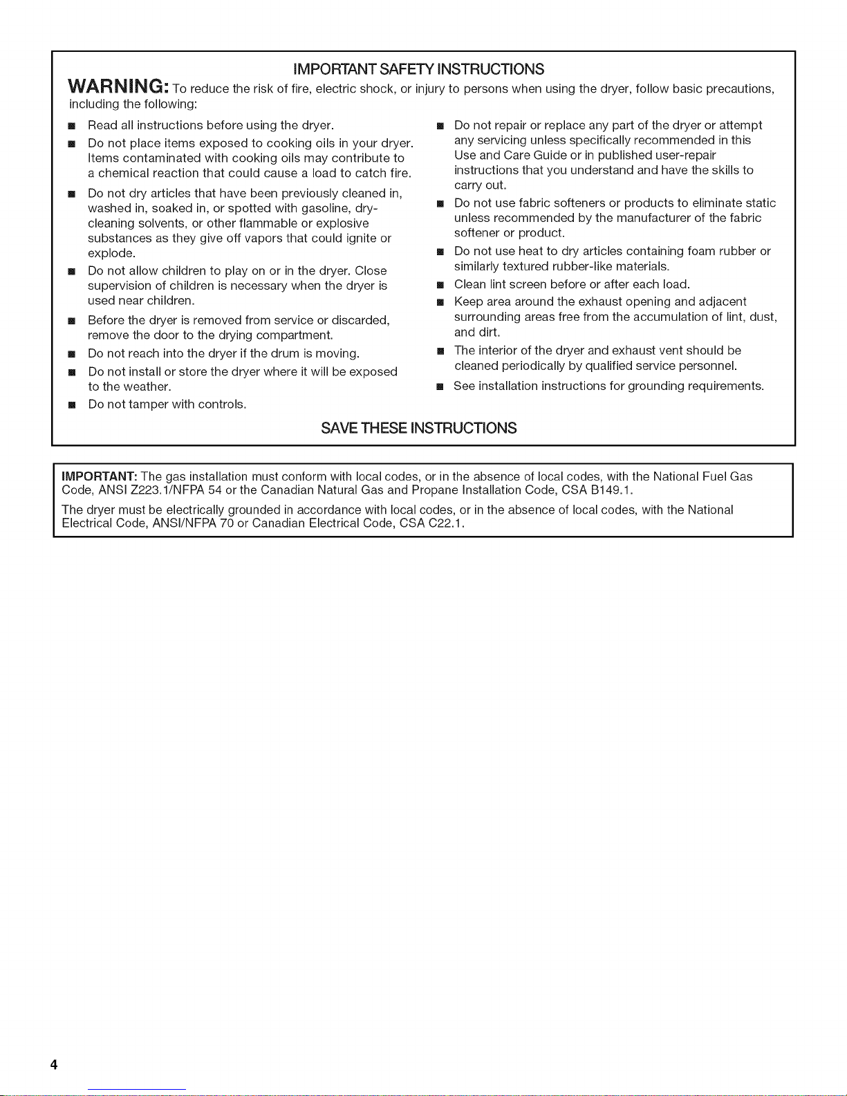
IMPORTANT SAFETY INSTRUCTIONS
WAR NiNG" To reduce the risk of fire, electric shock, or injury to persons when using the dryer, follow basic precautions,
including the following:
[] Read all instructions before using the dryer.
[] Do not place items exposed to cooking oils in your dryer.
Items contaminated with cooking oils may contribute to
a chemical reaction that could cause a load to catch fire.
[] Do not dry articles that have been previously cleaned in,
washed in, soaked in, or spotted with gasoline, dry-
cleaning solvents, or other flammable or explosive
substances as they give off vapors that could ignite or
explode.
[] Do not allow children to play on or in the dryer. Close
supervision of children is necessary when the dryer is
used near children.
[] Before the dryer is removed from service or discarded,
remove the door to the drying compartment.
[] Do not reach into the dryer if the drum is moving.
[] Do not install or store the dryer where it will be exposed
to the weather.
[] Do not tamper with controls.
SAVE THESE INSTRUCTIONS
[] Do not repair or replace any part of the dryer or attempt
any servicing unless specifically recommended in this
Use and Care Guide or in published user-repair
instructions that you understand and have the skills to
carry out.
[] Do not use fabric softeners or products to eliminate static
unless recommended by the manufacturer of the fabric
softener or product.
[] Do not use heat to dry articles containing foam rubber or
similarly textured rubber-like materials.
[] Clean lint screen before or after each load.
[] Keep area around the exhaust opening and adjacent
surrounding areas free from the accumulation of lint, dust,
and dirt.
[] The interior of the dryer and exhaust vent should be
cleaned periodically by qualified service personnel.
[] See installation instructions for grounding requirements.
iMPORTANT: The gas installation must conform with local codes, or inthe absence of local codes, with the National Fuel Gas
Code, ANSI Z223.1/NFPA 54 or the Canadian Natural Gas and Propane Installation Code, CSA B149.1.
The dryer must be electrically grounded in accordance with local codes, or in the absence of local codes, with the National
Electrical Code, ANSI/NFPA 70 or Canadian Electrical Code, CSA C22.1.
INSTALLATIONINSTRUCTIONS
Gather the required tools and parts before starting installation.
Read and follow the instructions provided with any tools listed
here.
8" or 10" pipe wrench •
8" or 10" adjustable
wrench (for gas •
connections) •
Flat-blade screwdriver
Adjustable wrench that
opens to 1" (2.5 cm) or
hex-head socket wrench
(for adjusting dryer feet)
Level
Parts supplied:
Remove parts package from dryer drum. Check that all parts
were included.
4 leveling legs
Parts needed:
Check local codes and consult gas supplier. Check existing gas
supply, electrical supply and venting, and read "Electrical
Requirements," "Gas Supply Requirements" and "Venting
Requirements" before purchasing parts.
Mobile home installations require special parts (listed following)
that may be ordered by calling the dealer from whom you
purchased your dryer. For information on ordering, please refer to
the "Assistance or Service" section. You may also contact the
dealer from whom you purchased your dryer.
• Mobile home installation kit. Ask for Part Number 346764.
• Metal exhaust system hardware.
¼"nut driverorsocket
wrench
Knife
Vent clamps
Pipe-joint compound
resistant to LP gas
Caulking gun and
compound (for installing
new exhaust vent)
Pliers
Explosion Hazard
Keep flammable materials and vapors, such as
gasoline, away from dryer.
Place dryer at least 18 inches (46 cm) above the floor
for a garage installation.
Failure to do so can result in death, explosion, or fire.
You will need
• A location that allows for proper exhaust installation. See
"Venting Requirements."
• A separate 30-amp circuit.
• A grounded electrical outlet located within 2 ft (61 cm) of
either side of the dryer. See "Electrical Requirements."
• A sturdy floor to support the total weight (dryer and load) of
200 Ibs (90.7 kg). The combined weight of a companion
appliance should also be considered.
• A level floor with a maximum slope of 1" (2.5 cm) under entire
dryer.
Do not operate your dryer at temperatures below 45°F (7°C). At
lower temperatures, the dryer might not shut off at the end of an
automatic cycle. Drying times can be extended.
The dryer must not be installed or stored in an area where it will
be exposed to water and/or weather.
Check code requirements. Some codes limit, or do not permit,
installation of the dryer in garages, closets, mobile homes or
sleeping quarters. Contact your local building inspector.
NOTE: No other fuel-burning appliance can be installed in the
same closet as a dryer.
Installation Clearances
The location must be large enough to allow the dryer door to
open fully.
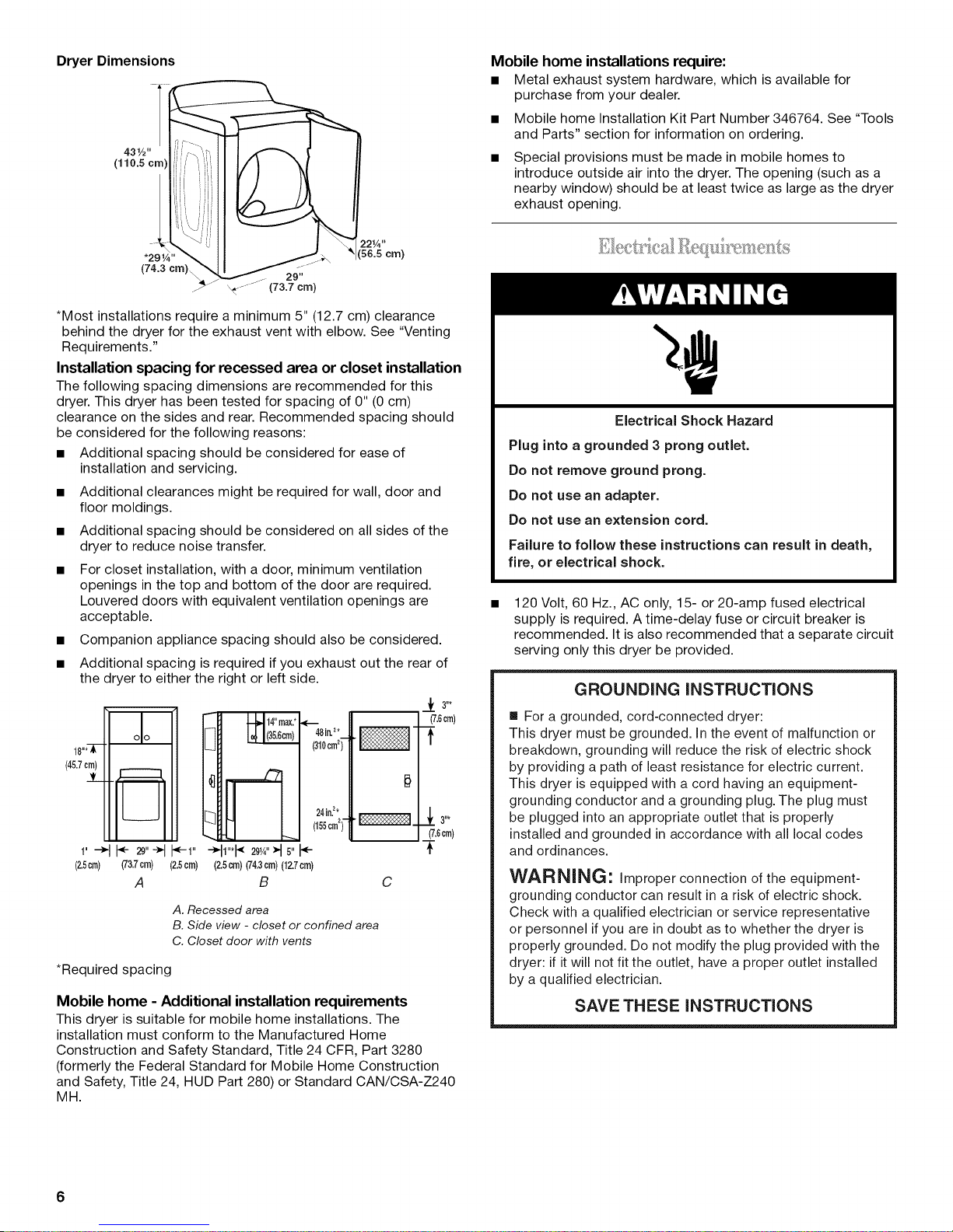
Dryer Dimensions
5z21./_"crn)
*Most installations require a minimum 5" (12.7 cm) clearance
behind the dryer for the exhaust vent with elbow. See "Venting
Requirements."
Installation spacing for recessed area or closet installation
The following spacing dimensions are recommended for this
dryer. This dryer has been tested for spacing of 0" (0 cm)
clearance on the sides and rear. Recommended spacing should
be considered for the following reasons:
• Additional spacing should be considered for ease of
installation and servicing.
• Additional clearances might be required for wall, door and
floor moldings.
• Additional spacing should be considered on all sides of the
dryer to reduce noise transfer.
• For closet installation, with a door, minimum ventilation
openings in the top and bottom of the door are required.
Louvered doors with equivalent ventilation openings are
acceptable.
• Companion appliance spacing should also be considered.
• Additional spacing is required if you exhaust out the rear of
the dryer to either the right or left side.
_f 3"*
(7.6cm)
¢6om)
i
(45.7cm)
1"-_ _ _"-_ _1" 1"*I_2_,4"_15"÷
(2.5cm) (73.7crn) (2.5crn) (2.5crn)(74.3cm)(12.7crn)
A B
A. Recessed area
B. Side view - closet or confined area
C. Closet door with vents
481n.2._
(310cm2)
24in.z*
(155cm2)-
C
*Required spacing
Mobile home - Additional installation requirements
This dryer is suitable for mobile home installations. The
installation must conform to the Manufactured Home
Construction and Safety Standard, Title 24 CFR, Part 3280
(formerly the Federal Standard for Mobile Home Construction
and Safety, Title 24, HUD Part 280) or Standard CAN/CSA-Z240
MH.
Mobile home installations require:
• Metal exhaust system hardware, which is available for
purchase from your dealer.
• Mobile home Installation Kit Part Number 346764. See "Tools
and Parts" section for information on ordering.
• Special provisions must be made in mobile homes to
introduce outside air into the dryer. The opening (such as a
nearby window) should be at least twice as large as the dryer
exhaust opening.
Electrical Shock Hazard
Plug into a grounded 3 prong outlet.
Do not remove ground prong.
Do not use an adapter.
Do not use an extension cord.
Failure to follow these instructions can result in death,
fire, or electrical shock.
120 Volt, 60 Hz., AC only, 15- or 20-amp fused electrical
supply is required. A time-delay fuse or circuit breaker is
recommended. It is also recommended that a separate circuit
serving only this dryer be provided.
GROUNDING iNSTRUCTiONS
[] For a grounded, cord-connected dryer:
This dryer must be grounded. In the event of malfunction or
breakdown, grounding will reduce the risk of electric shock
by providing a path of least resistance for electric current.
This dryer is equipped with a cord having an equipment-
grounding conductor and a grounding plug. The plug must
be plugged into an appropriate outlet that is properly
installed and grounded in accordance with all local codes
and ordinances.
WARNING: Improper connection of the equipment-
grounding conductor can result in a risk of electric shock.
Check with a qualified electrician or service representative
or personnel if you are in doubt as to whether the dryer is
properly grounded. Do not modify the plug provided with the
dryer: if it will not fit the outlet, have a proper outlet installed
by a qualified electrician.
SAVE THESE INSTRUCTIONS
6
Explosion Hazard
Use a new CSA (nternational approved gas supply line.
Install a shut=off valve.
Securely tighten all gas connections.
if connected to LP, have a qualified person make sure
gas pressure does not exceed 13" (33 cm) water
column.
Examples of a qualified person include:
licensed heating personnel,
authorized gas company personnel, and
authorized service personnel.
Failure to do so can result in death, explosion, or fire.
Gas Type
• 3/8"flare x 3/8"NPT adapter fitting between dryer pipe and 3/8"
approved tubing.
• Lengths over 20 ft (6.1 m) should use larger tubing and a
different size adapter fitting.
• If your dryer has been converted to use LP gas, 3/8"LP
compatible copper tubing can be used. If the total length of
the supply line is more than 20 ft (6.1 m), use larger pipe.
NOTE: Pipe-joint compounds that resist the action of LP gas
must be used. Do not use TEFLON ®ttape.
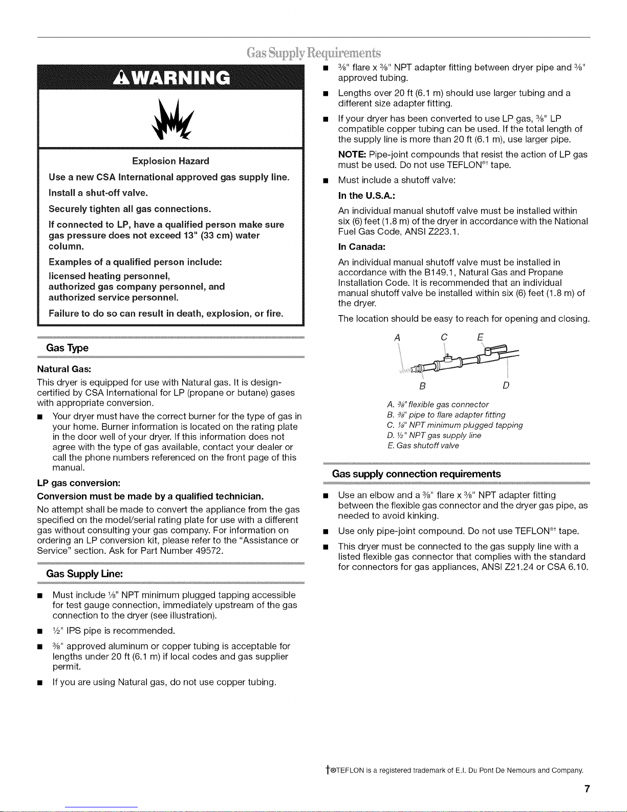
• Must include a shutoff valve:
In the U.S.A.:
An individual manual shutoff valve must be installed within
six (6)feet (1.8 m) of the dryer in accordance with the National
Fuel Gas Code, ANSI Z223.1.
In Canada:
An individual manual shutoff valve must be installed in
accordance with the B149.1, Natural Gas and Propane
Installation Code. It is recommended that an individual
manual shutoff valve be installed within six (6)feet (1.8 m) of
the dryer.
The location should be easy to reach for opening and closing.
A C E
Natural Gas:
This dryer is equipped for use with Natural gas. It is design-
certified by CSA International for LP (propane or butane) gases
with appropriate conversion.
• Your dryer must have the correct burner for the type of gas in
your home. Burner information is located on the rating plate
in the door well of your dryer. If this information does not
agree with the type of gas available, contact your dealer or
call the phone numbers referenced on the front page of this
manual.
LP gas conversion:
Conversion must be made by a qualified technician.
No attempt shall be made to convert the appliance from the gas
specified on the model/serial rating plate for use with a different
gas without consulting your gas company. For information on
ordering an LP conversion kit, please refer to the "Assistance or
Service" section. Ask for Part Number 49572.
Gas Supply Line:
• Must include 1/8"NPT minimum plugged tapping accessible
for test gauge connection, immediately upstream of the gas
connection to the dryer (see illustration).
• 1/2"IPS pipe is recommended.
• 3/8"approved aluminum or copper tubing is acceptable for
lengths under 20 ft (6.1 m) if local codes and gas supplier
permit.
• If you are using Natural gas, do not use copper tubing.
B D
A. _" flexible gas connector
B. _" pipe to flare adapter fitting
C. _" NPT minimum plugged tapping
D. 7/2"NPT gas supply fine
E. Gas shutoff valve
Gas supply connection requirements
• Use an elbow and a 3/8"flare x 3/8"NPT adapter fitting
between the flexible gas connector and the dryer gas pipe, as
needed to avoid kinking.
• Use only pipe-joint compound. Do not use TEFLON ®ttape.
• This dryer must be connected to the gas supply line with a
listed flexible gas connector that complies with the standard
for connectors for gas appliances, ANSI Z21.24 or CSA 6.10.
1-®TEFLON is a registered trademark of E.I. Du Pont De Nemours and Company.
7
Burner Input Requirements:
If this is a new vent system
Elevations above 10,000 ft (3,048 m):
• When installed above 10,000 ft (3,048 m) a 4% reduction of
the burner Btu rating shown on the model/serial number plate
is required for each 1,000 ft (305 m) increase in elevation.
Gas Supply Pressure Testing
• The dryer must be disconnected from the gas supply piping
system during pressure testing at pressures greater than
1/2psi.
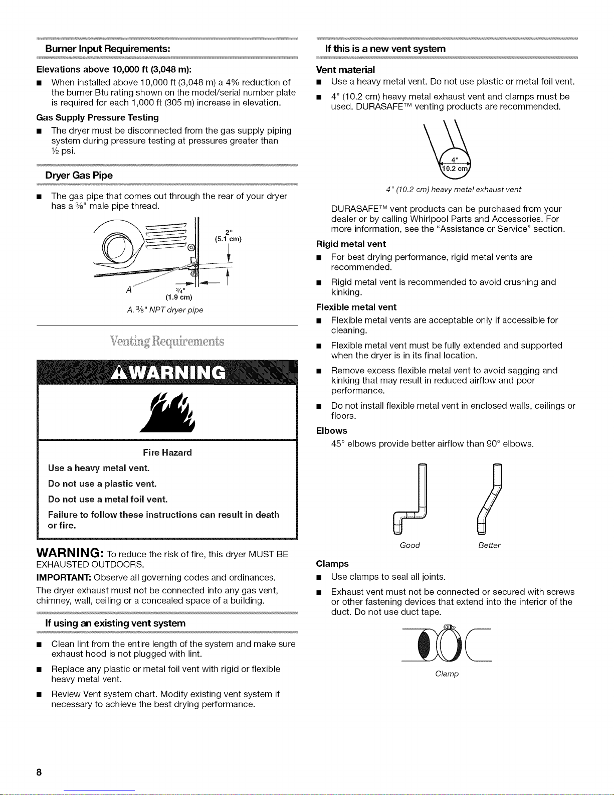
Dryer Gas Pipe
• The gas pipe that comes out through the rear of your dryer
has a 3/8"male pipe thread.
2 It
(5.1crn)
A ¸ 3/4-
(1.9crn)
A.3/8"NPTdryer pipe
Fire Hazard
Use a heavy metal vent.
Do not use a plastic vent.
Do not use a metal foil vent.
Failure to follow these instructions can result in death
or fire.
Vent material
• Use a heavy metal vent. Do not use plastic or metal foil vent.
• 4" (10.2 cm) heavy metal exhaust vent and clamps must be
used. DURASAFE TM venting products are recommended.
4" (10.2cm) heavymetal exhaust vent
DURASAFE TM vent products can be purchased from your
dealer or by calling Whirlpool Parts and Accessories. For
more information, see the "Assistance or Service" section.
Rigid metal vent
• For best drying performance, rigid metal vents are
recommended.
• Rigid metal vent is recommended to avoid crushing and
kinking.
Flexible metal vent
• Flexible metal vents are acceptable only if accessible for
cleaning.
• Flexible metal vent must be fully extended and supported
when the dryer is in its final location.
• Remove excess flexible metal vent to avoid sagging and
kinking that may result in reduced airflow and poor
performance.
• Do not install flexible metal vent in enclosed walls, ceilings or
floors.
Elbows
45° elbows provide better airflow than 90° elbows.
S
WARNING: To reduce the risk of fire, this dryer MUST BE
EXHAUSTED OUTDOORS.
IMPORTANT: Observe all governing codes and ordinances.
The dryer exhaust must not be connected into any gas vent,
chimney, wall, ceiling or a concealed space of a building.
If using an existing vent system
• Clean lint from the entire length of the system and make sure
exhaust hood is not plugged with lint.
• Replace any plastic or metal foil vent with rigid or flexible
heavy metal vent.
• Review Vent system chart. Modify existing vent system if
necessary to achieve the best drying performance.
8
Good Better
Clamps
• Use clamps to seal all joints.
• Exhaust vent must not be connected or secured with screws
or other fastening devices that extend into the interior of the
duct. Do not use duct tape.
Clamp
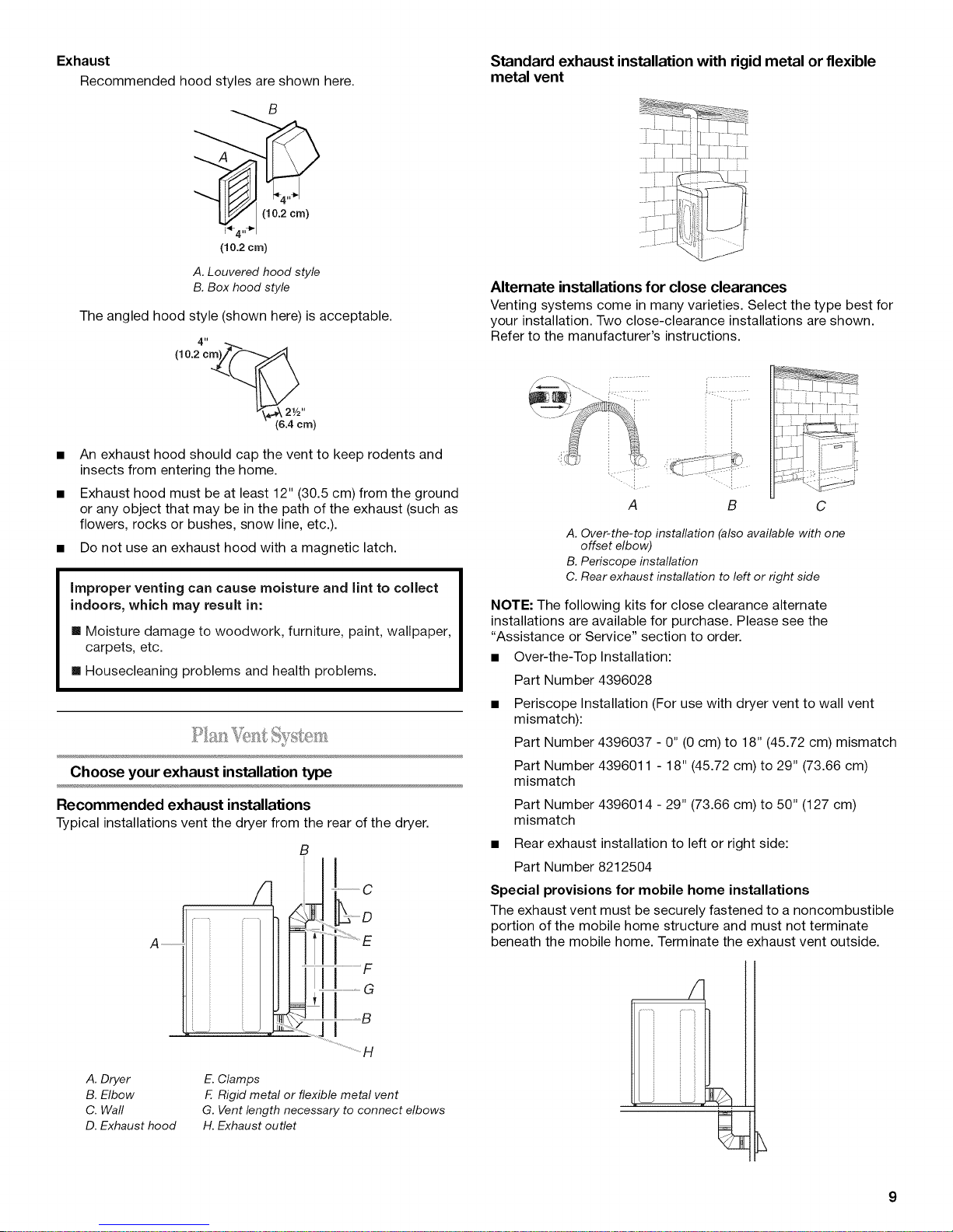
Exhaust
Recommended hood styles are shown here.
(10.2cm)
A. Louvered hood style
B. Box hood style
The angled hood style (shown here) is acceptable.
4"
Standard exhaust installation with rigid metal or flexible
metal vent
Alternate installations for close clearances
Venting systems come in many varieties. Select the type best for
your installation. Two close-clearance installations are shown.
Refer to the manufacturer's instructions.
(10.2cm)__
• An exhaust hood should cap the vent to keep rodents and
insects from entering the home.
• Exhaust hood must be at least 12" (30.5 cm) from the ground
or any object that may be in the path of the exhaust (such as
flowers, rocks or bushes, snow line, etc.).
• Do not use an exhaust hood with a magnetic latch.
improper venting can cause moisture and lint to collect
indoors, which may result in:
[] Moisture damage to woodwork, furniture, paint, wallpaper,
carpets, etc.
[] Housecleaning problems and health problems.
Choose your exhaust installation type
Recommended exhaust installations
Typicalinstallationsvent the dryer from the rear of the dryer.
B
A
!..... i....
A B C
A. Over-the-top installation (also available with one
offset elbow)
B.Periscope installation
C. Rear exhaust installation to left or right side
NOTE: The following kits for close clearance alternate
installations are available for purchase. Please see the
"Assistance or Service" section to order.
• Over-the-Top Installation:
Part Number 4396028
Periscope Installation (For use with dryer vent to wall vent
mismatch):
Part Number 4396037 - 0" (0 cm) to 18" (45.72 cm) mismatch
Part Number 4396011 - 18" (45.72 cm) to 29" (73.66 cm)
mismatch
Part Number 4396014 - 29" (73.66 cm) to 50" (127 cm)
mismatch
Rear exhaust installation to left or right side:
Part Number 8212504
Special provisions for mobile home installations
The exhaust vent must be securely fastened to a noncombustible
portion of the mobile home structure and must not terminate
beneath the mobile home. Terminate the exhaust vent outside.
|-i CG
A. Dryer
B. Elbow
C. Wall
D. Exhaust hood
E.Clamps
E Rigid metal or flexible metal vent
G. Vent length necessary to connect elbows
H. Exhaust outlet
f
_1.................................
...............H
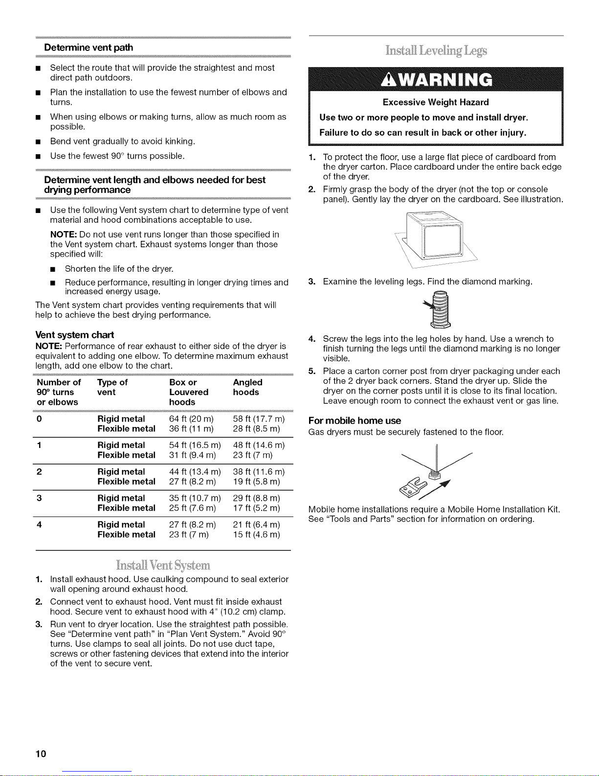
Determine vent path
• Select the route that will provide the straightest and most
direct path outdoors.
• Plan the installation to use the fewest number of elbows and
turns.
• When using elbows or making turns, allow as much room as
possible.
• Bend vent gradually to avoid kinking.
• Use the fewest 90° turns possible.
Determine vent length and elbows needed for best
drying performance
• Use the following Vent system chart to determine type of vent
material and hood combinations acceptable to use.
NOTE: Do not use vent runs longer than those specified in
the Vent system chart. Exhaust systems longer than those
specified will:
• Shorten the life of the dryer.
• Reduce performance, resulting in longer drying times and
increased energy usage.
The Vent system chart provides venting requirements that will
help to achieve the best drying performance.
..... _ _ _7_w_ _S__
...... 9
Excessive Weight Hazard
Use two or more people to move and install dryer.
Failure to do so can result in back or other injury.
1. To protect the floor, use a large flat piece of cardboard from
the dryer carton. Place cardboard under the entire back edge
of the dryer.
2. Firmly grasp the body of the dryer (not the top or console
panel). Gently lay the dryer on the cardboard. See illustration.
3. Examine the leveling legs. Find the diamond marking.
Vent system chart
NOTE: Performance of rear exhaust to either side of the dryer is
equivalent to adding one elbow. To determine maximum exhaust
length, add one elbow to the chart.
Number of Type of Box or Angled
90° turns vent Louvered hoods
or elbows hoods
0 Rigid metal 64 ft (20 m) 58 ft (17.7 m)
Flexible metal 36 ft (11 m) 28 ft (8.5 m)
1 Rigid metal 54 ft (16.5 m) 48 ft (14.6 m)
Flexible metal 31 ft (9.4 m) 23 ft (7 m)
2 Rigid metal 44 ft (13.4 m) 38 ft (11.6 m)
Flexible metal 27 ft (8.2 m) 19 ft (5.8 m)
3 Rigid metal 35 ft (10.7 m) 29 ft (8.8 m)
Flexible metal 25 ft (7.6 m) 17 ft (5.2 m)
4 Rigid metal 27 ft (8.2 m) 21 ft (6.4 m)
Flexible metal 23 ft (7 m) 15 ft (4.6 m)
1.
Install exhaust hood. Use caulking compound to seal exterior
wall opening around exhaust hood.
2.
Connect vent to exhaust hood. Vent must fit inside exhaust
hood. Secure vent to exhaust hood with 4" (10.2 cm) clamp.
3.
Run vent to dryer location. Use the straightest path possible.
See "Determine vent path" in "Plan Vent System." Avoid 90°
turns. Use clamps to seal all joints. Do not use duct tape,
screws or other fastening devices that extend into the interior
of the vent to secure vent.
4. Screw the legs into the leg holes by hand. Use a wrench to
finish turning the legs until the diamond marking is no longer
visible.
5. Place a carton corner post from dryer packaging under each
of the 2 dryer back corners. Stand the dryer up. Slide the
dryer on the corner posts until it is close to its final location.
Leave enough room to connect the exhaust vent or gas line.
For mobile home use
Gas dryers must be securely fastened to the floor.
Mobile home installations require a Mobile Home Installation Kit.
See "Tools and Parts" section for information on ordering.
10
R¸- / ......
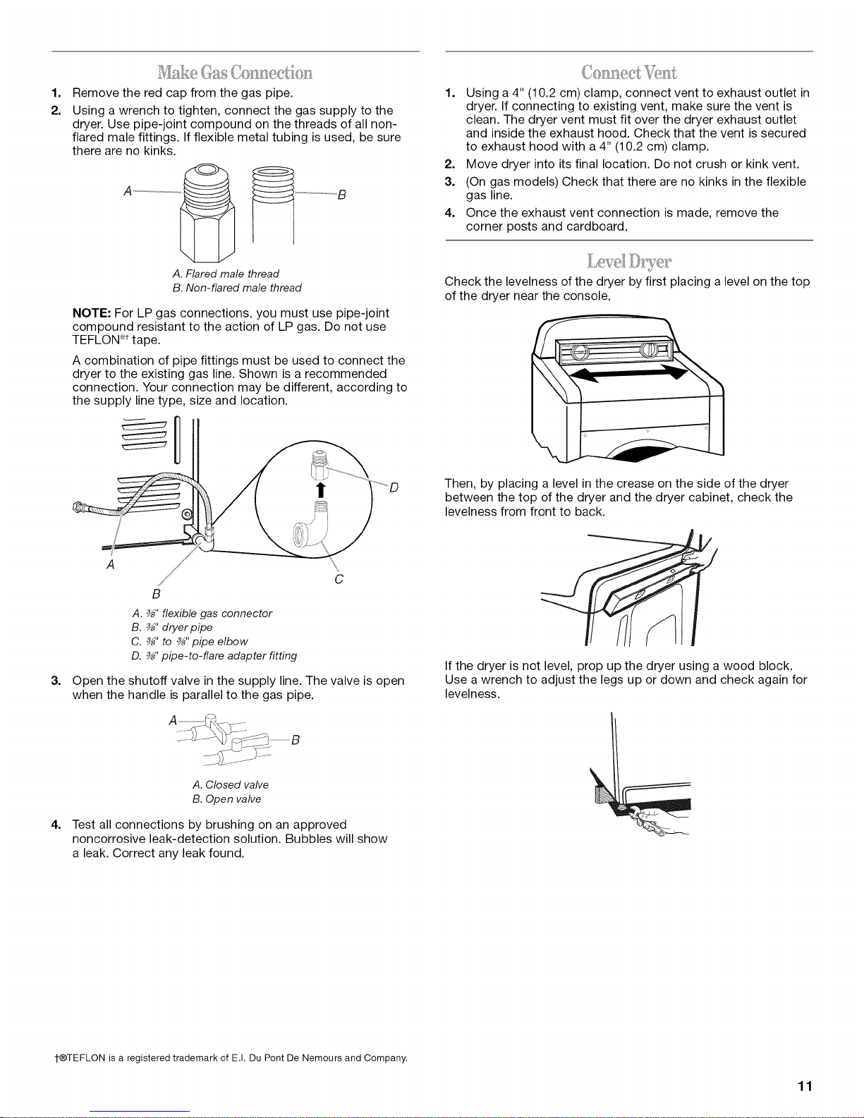
1.
Remove the red cap from the gas pipe.
2.
Using a wrench to tighten, connect the gas supply to the
dryer. Use pipe-joint compound on the threads of all non-
flared male fittings. If flexible metal tubing is used, be sure
there are no kinks.
.... g
A ................
1. Using a 4" (10.2 cm) clamp, connect vent to exhaust outlet in
dryer. If connecting to existing vent, make sure the vent is
clean. The dryer vent must fit over the dryer exhaust outlet
and inside the exhaust hood. Check that the vent is secured
to exhaust hood with a 4" (10.2 cm) clamp.
2. Move dryer into its final location. Do not crush or kink vent.
3. (On gas models) Check that there are no kinks in the flexible
gas line.
4. Once the exhaust vent connection is made, remove the
corner posts and cardboard.
A.Flared male thread
B.Non-flared male thread
NOTE: For LP gas connections, you must use pipe-joint
compound resistant to the action of LP gas. Do not use
TEFLON®ttape.
A combination of pipe fittings must be used to connect the
dryer to the existing gas line. Shown is a recommended
connection. Your connection may be different, according to
the supply line type, size and location.
I
C
B
A. _" flexible gas connector
B. _" dryer pipe
C. _" to _" pipe elbow
D. _" pipe-to-flare adapter fitting
3.
Open the shutoff valve in the supply line. The valve is open
when the handle is parallel to the gas pipe.
Check the levelness of the dryer by first placing a level on the top
of the dryer near the console.
Then, by placing a level in the crease on the side of the dryer
between the top of the dryer and the dryer cabinet, check the
levelness from front to back.
If the dryer is not level, prop up the dryer using a wood block.
Use a wrench to adjust the legs up or down and check again for
levelness.
A. Closed valve
B. Open valve
4.
Test all connections by brushing on an approved
noncorrosive leak-detection solution. Bubbles will show
a leak. Correct any leak found.
t®TEFLON is a registered trademark of E.I. Du Pont De Nemours and Company.
11

You can change your door swing from a right-side opening to a
left-side opening, if desired.
1. Place a towel or soft cloth on top of the dryer or work space
to protect the surface.
Remove the door assembly
1. Open the dryer door.
2. Remove the bottom screw from each of the 2 hinges that
attach the dryer door to the front panel of the dryer.
3. Loosen the top screw from each of the 2 hinges in Step 2.
A
B
A
B
A, Loosen these screws.
B. Remove these screws.
Reverse the strike
1. Remove the door strike from the dryer door opening.
2. Remove the cosmetic screw opposite the door strike.
A. Door strike
B. Cosmetic screw
3. Reinstall the door strike and cosmetic screw on the opposite
side of the dryer door opening from where they were
removed.
NOTE: Door strike and plugs must be on the same side of the
dryer door opening.
Reinstall the door
1.
Remove the 4 screws and 2 hinges from the dryer door.
2.
Replace the 4 screws in the same holes.
4. Remove the dryer door and the hinges by lifting upward on
the door. Lay the door on a flat, protected surface, with the
inside of the door facing up. Remove remaining 2 loose
screws from dryer front panel.
5. Remove the 4 plastic plugs located outside the dryer door
opening.
II
_c
II
6.
Install 4 plastic plugs into screw holes in the dryer left where
the hinges were removed in Step 4.
3. Remove the 4 screws from the opposite side of the door.
!
®_q[:--
I
12
\
I
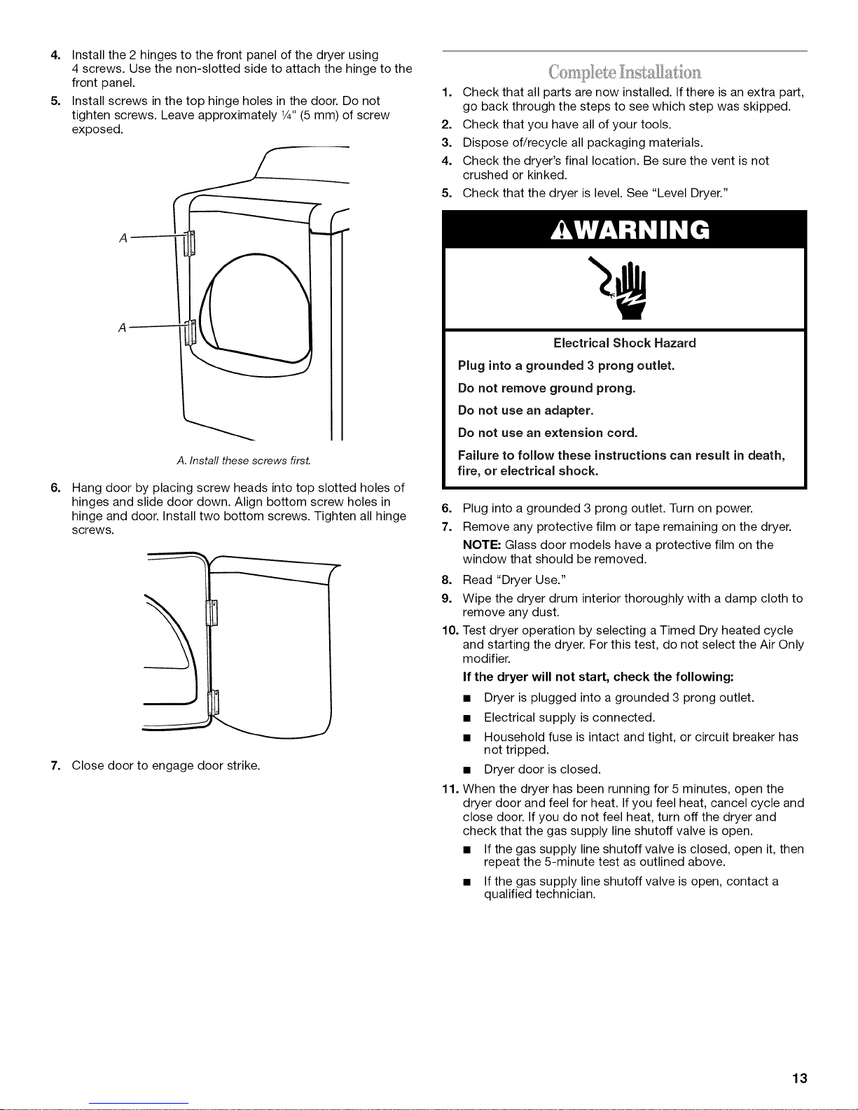
4. Install the 2 hinges to the front panel of the dryer using
4 screws. Use the non-slotted side to attach the hinge to the
front panel.
5. Install screws in the top hinge holes in the door. Do not
tighten screws. Leave approximately 1¼,,(5 mm) of screw
exposed.
A. Install these screws firsL
6=
Hang door by placing screw heads into top slotted holes of
hinges and slide door down. Align bottom screw holes in
hinge and door. Install two bottom screws. Tighten all hinge
screws.
7. Close door to engage door strike.
1. Check that all parts are now installed. If there is an extra part,
go back through the steps to see which step was skipped.
2. Check that you have all of your tools.
3. Dispose of/recycle all packaging materials.
4. Check the dryer's final location. Be sure the vent is not
crushed or kinked.
5. Check that the dryer is level. See "Level Dryer."
Electrical Shock Hazard
Plug into a grounded 3 prong outlet.
Do not remove ground prong.
Do not use an adapter.
Do not use an extension cord.
Failure to follow these instructions can result in death,
fire, or electrical shock.
6=
Plug into a grounded 3 prong outlet. Turn on power.
7.
Remove any protective film or tape remaining on the dryer.
NOTE: Glass door models have a protective film on the
window that should be removed.
8. Read "Dryer Use."
9. Wipe the dryer drum interior thoroughly with a damp cloth to
remove any dust.
10. Test dryer operation by selecting a Timed Dry heated cycle
and starting the dryer. For this test, do not select the Air Only
modifier.
If the dryer will not start, check the following:
• Dryer is plugged into a grounded 3 prong outlet.
• Electrical supply is connected.
• Household fuse is intact and tight, or circuit breaker has
not tripped.
• Dryer door is closed.
11. When the dryer has been running for 5 minutes, open the
dryer door and feel for heat. If you feel heat, cancel cycle and
close door. If you do not feel heat, turn off the dryer and
check that the gas supply line shutoff valve is open.
• If the gas supply line shutoff valve is closed, open it, then
repeat the 5-minute test as outlined above.
• If the gas supply line shutoff valve is open, contact a
qualified technician.
13
DRYERUSE
\
f Cool w_nkle \
"_ NN\
/ More edium Di_UMLIGHT \\
// _ormal _w '\
/
slANt \
/" DRY QUICK T H ,
/ DRY
TIMEC OUUpC
9RYN[SS T[MP 9AMP ONY ENDOF CYCLE
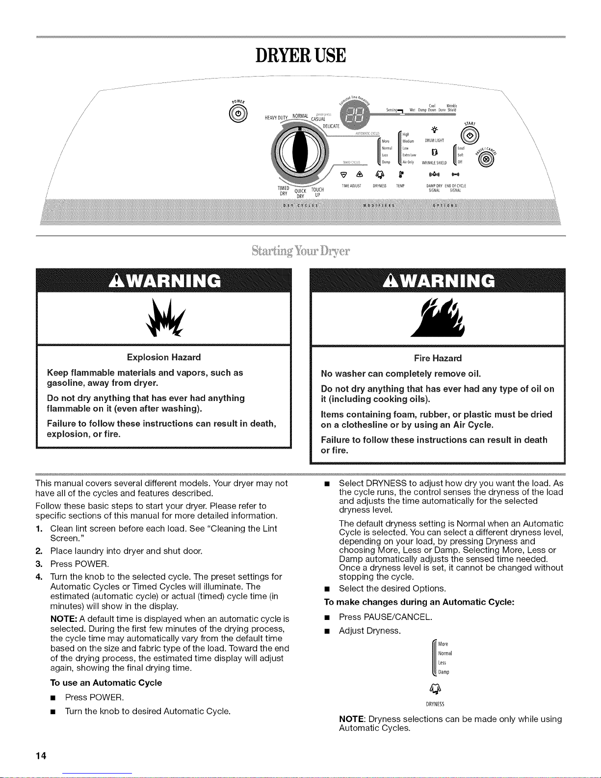
Explosion Hazard
Keep flammable materials and vapors, such as
gasoline, away from dryer.
Do not dry anything that has ever had anything
flammable on it (even after washing).
Failure to follow these instructions can result in death,
explosion, or fire.
No washer can completely remove oil.
Do not dry anything that has ever had any type of oil on
it (including cooking oils).
Items containing foam, rubber, or plastic must be dried
on a clothesline or by using an Air Cycle.
Failure to follow these instructions can result in death
SIGNAL SIGNAL
Fire Hazard
or fire.
This manual covers several different models. Your dryer may not •
have all of the cycles and features described.
Follow these basic steps to start your dryer. Please refer to
specific sections of this manual for more detailed information.
1. Clean lint screen before each load. See "Cleaning the Lint
Screen."
2. Place laundry into dryer and shut door.
3. Press POWER.
4. Turn the knob to the selected cycle. The preset settings for
Automatic Cycles or Timed Cycles will illuminate. The •
estimated (automatic cycle) or actual (timed) cycle time (in
minutes) will show in the display.
NOTE: A default time is displayed when an automatic cycle is
selected. During the first few minutes of the drying process,
the cycle time may automatically vary from the default time
based on the size and fabric type of the load. Toward the end
of the drying process, the estimated time display will adjust
again, showing the final drying time.
To use an Automatic Cycle
• Press POWER.
• Turn the knob to desired Automatic Cycle.
14
Select DRYNESS to adjust how dry you want the load. As
the cycle runs, the control senses the dryness of the load
and adjusts the time automatically for the selected
dryness level.
The default dryness setting is Normal when an Automatic
Cycle is selected. You can select a different dryness level,
depending on your load, by pressing Dryness and
choosing More, Less or Damp. Selecting More, Less or
Damp automatically adjusts the sensed time needed.
Once a dryness level is set, it cannot be changed without
stopping the cycle.
Select the desired Options.
To make changes during an Automatic Cycle:
• Press PAUSE/CANCEL.
• Adjust Dryness.
DRYNESS
NOTE: Dryness selections can be made only while using
Automatic Cycles.
How the AccelerCare TM Drying System Works
Moisture-sensing strips inside the dryer drum and
temperature sensors in the airstream monitor how fast the
load is drying, how hot the air should be and when clothes
are dry. The system automatically stops the cycle to help
save time and avoid overdrying.
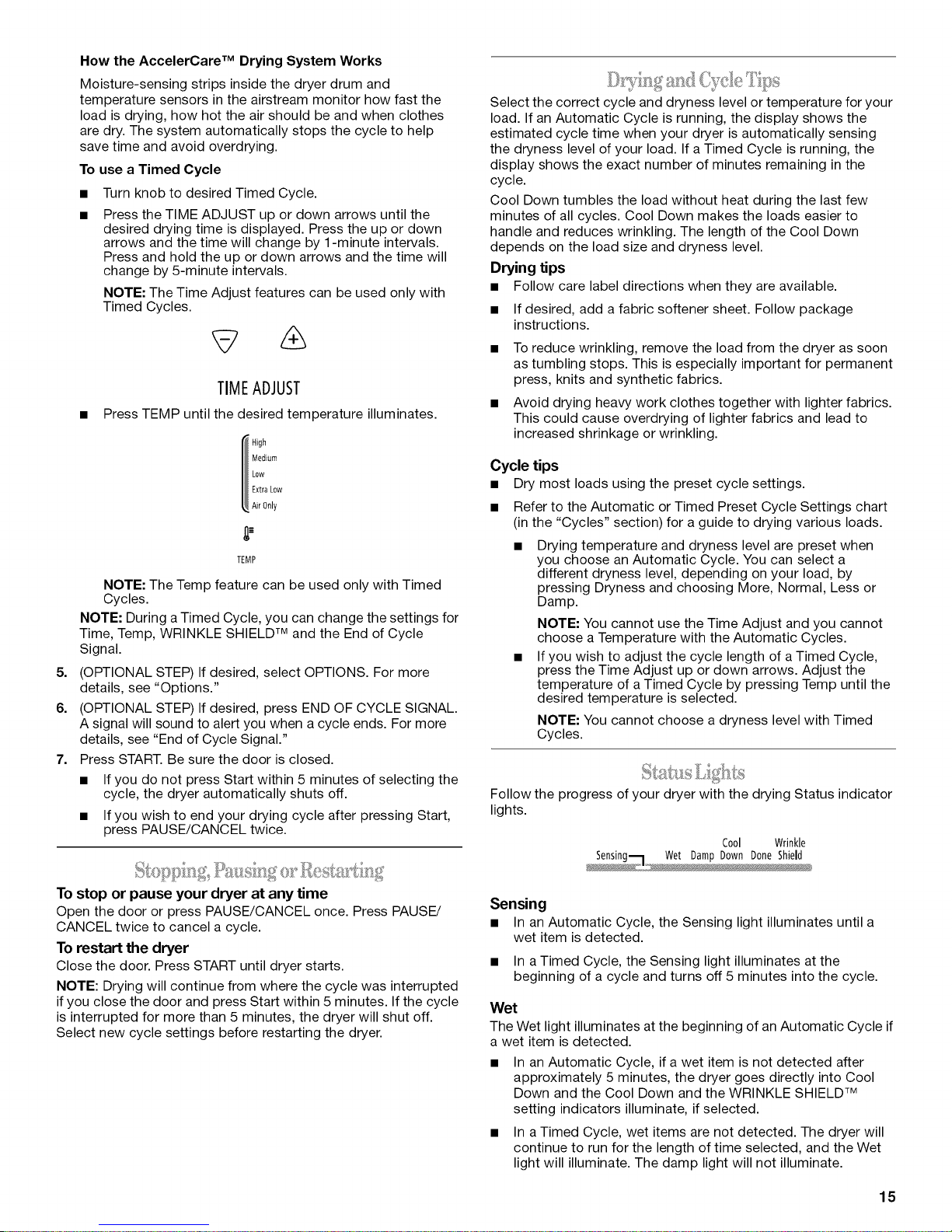
To use a Timed Cycle
• Turn knob to desired Timed Cycle.
• Press the TIME ADJUST up or down arrows until the
desired drying time is displayed. Press the up or down
arrows and the time will change by 1-minute intervals.
Press and hold the up or down arrows and the time will
change by 5-minute intervals.
NOTE: The Time Adjust features can be used only with
Timed Cycles.
TIMEADJUST
• Press TEMP until the desired temperature illuminates.
TEMP
NOTE: The Temp feature can be used only with Timed
Cycles.
NOTE: During a Timed Cycle, you can change the settings for
Time, Temp, WRINKLE SHIELD TM and the End of Cycle
Signal.
5=
(OPTIONAL STEP) If desired, select OPTIONS. For more
details, see "Options."
6.
(OPTIONAL STEP) If desired, press END OF CYCLE SIGNAL.
A signal will sound to alert you when a cycle ends. For more
details, see "End of Cycle Signal."
7=
Press START. Be sure the door is closed.
• If you do not press Start within 5 minutes of selecting the
cycle, the dryer automatically shuts off.
• If you wish to end your drying cycle after pressing Start,
press PAUSE/CANCEL twice.
Select the correct cycle and dryness level or temperature for your
load. If an Automatic Cycle is running, the display shows the
estimated cycle time when your dryer is automatically sensing
the dryness level of your load. If a Timed Cycle is running, the
display shows the exact number of minutes remaining in the
cycle.
Cool Down tumbles the load without heat during the last few
minutes of all cycles. Cool Down makes the loads easier to
handle and reduces wrinkling. The length of the Cool Down
depends on the load size and dryness level.
Drying tips
• Follow care label directions when they are available.
• If desired, add a fabric softener sheet. Follow package
instructions.
• To reduce wrinkling, remove the load from the dryer as soon
as tumbling stops. This is especially important for permanent
press, knits and synthetic fabrics.
• Avoid drying heavy work clothes together with lighter fabrics.
This could cause overdrying of lighter fabrics and lead to
increased shrinkage or wrinkling.
Cycle tips
• Dry most loads using the preset cycle settings.
• Refer to the Automatic or Timed Preset Cycle Settings chart
(in the "Cycles" section) for a guide to drying various loads.
Drying temperature and dryness level are preset when
you choose an Automatic Cycle. You can select a
different dryness level, depending on your load, by
pressing Dryness and choosing More, Normal, Less or
Damp.
NOTE: You cannot use the Time Adjust and you cannot
choose a Temperature with the Automatic Cycles.
If you wish to adjust the cycle length of a Timed Cycle,
press the Time Adjust up or down arrows. Adjust the
temperature of a Timed Cycle by pressing Temp until the
desired temperature is selected.
NOTE: You cannot choose a dryness level with Timed
Cycles.
Follow the progress of your dryer with the drying Status indicator
lights.
Cool Wrinkle
To stop or pause your dryer at any time
Open the door or press PAUSE/CANCEL once. Press PAUSE/
CANCEL twice to cancel a cycle.
To restart the dryer
Close the door. Press START until dryer starts.
NOTE: Drying will continue from where the cycle was interrupted
if you close the door and press Start within 5 minutes. If the cycle
is interrupted for more than 5 minutes, the dryer will shut off.
Select new cycle settings before restarting the dryer.
Sensing
• In an Automatic Cycle, the Sensing light illuminates until a
wet item is detected.
• In a Timed Cycle, the Sensing light illuminates at the
beginning of a cycle and turns off 5 minutes into the cycle.
Wet
The Wet light illuminates at the beginning of an Automatic Cycle if
a wet item is detected.
• In an Automatic Cycle, if a wet item is not detected after
approximately 5 minutes, the dryer goes directly into Cool
Down and the Cool Down and the WRINKLE SHIELD TM
setting indicators illuminate, if selected.
• In a Timed Cycle, wet items are not detected. The dryer will
continue to run for the length of time selected, and the Wet
light will illuminate. The damp light will not illuminate.
15
Damp
The Damp light illuminates in an Automatic Cycle when the
laundry is approximately 80% dry. Damp Dry Signal beeps, if
selected. See "Options."
Cool Down
The Cool Down light illuminates during the cool down part of the
cycle. Laundry cools for ease in handling.
Done
The Done light illuminates when the drying cycle is finished. This
indicator stays on during the WRINKLE SHIELD TM setting.
WRINKLE SHIELD TM Setting
The WRINKLE SHIELD TM setting light illuminates when this
option is selected. This indicator stays on during the WRINKLE
SHIELD TM setting.
Indicator lights
Other indicator lights show Cycle, Modifiers, Options and Cycle
Signal settings selected. The display shows the estimated or
actual time remaining.
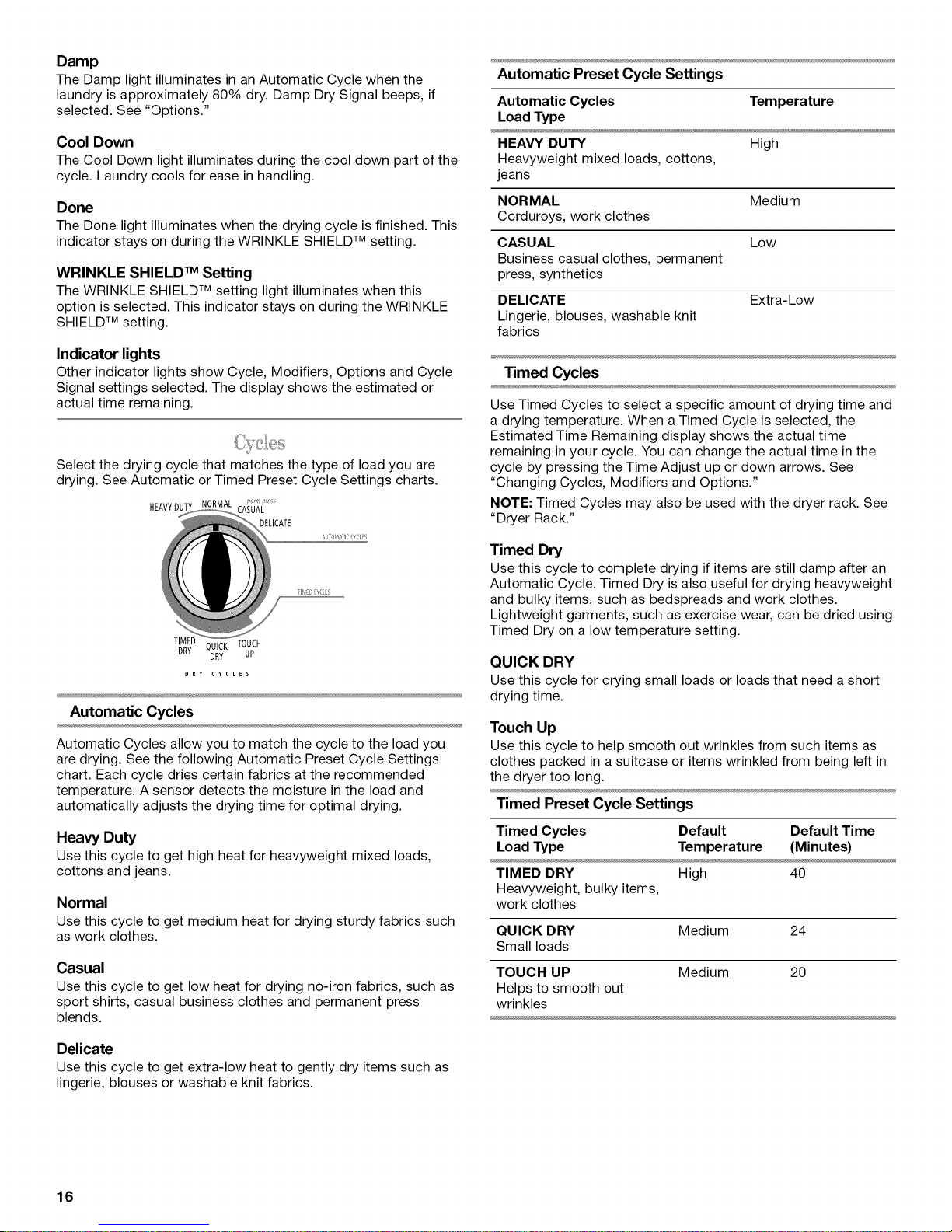
Select the drying cycle that matches the type of load you are
drying. See Automatic or Timed Preset Cycle Settings charts.
HEAVYDUTY CASUAL
DELICATE
Automatic Preset Cycle Settings
Automatic Cycles Temperature
Load Type
HEAVY DUTY High
Heavyweight mixed loads, cottons,
jeans
NORMAL Medium
Corduroys, work clothes
CASUAL Low
Business casual clothes, permanent
press, synthetics
DELICATE Extra-Low
Lingerie, blouses, washable knit
fabrics
Timed Cycles
Use Timed Cycles to select a specific amount of drying time and
a drying temperature. When a Timed Cycle is selected, the
Estimated Time Remaining display shows the actual time
remaining in your cycle. You can change the actual time in the
cycle by pressing the Time Adjust up or down arrows. See
"Changing Cycles, Modifiers and Options."
NOTE: Timed Cycles may also be used with the dryer rack. See
"Dryer Rack."
TIMED QUICK TOuUCH
DRY DRY
Automatic Cycles
Automatic Cycles allow you to match the cycle to the load you
are drying. See the following Automatic Preset Cycle Settings
chart. Each cycle dries certain fabrics at the recommended
temperature. A sensor detects the moisture in the load and
automatically adjusts the drying time for optimal drying.
Heavy Duty
Use this cycle to get high heat for heavyweight mixed loads,
cottons and jeans.
Normal
Use this cycle to get medium heat for drying sturdy fabrics such
as work clothes.
Casual
Use this cycle to get low heat for drying no-iron fabrics, such as
sport shirts, casual business clothes and permanent press
blends.
Timed Dry
Use this cycle to complete drying if items are still damp after an
Automatic Cycle. Timed Dry is also useful for drying heavyweight
and bulky items, such as bedspreads and work clothes.
Lightweight garments, such as exercise wear, can be dried using
Timed Dry on a low temperature setting.
QUICK DRY
Use this cycle for drying small loads or loads that need a short
drying time.
Touch Up
Use this cycle to help smooth out wrinkles from such items as
clothes packed in a suitcase or items wrinkled from being left in
the dryer too long.
Timed Preset Cycle Settings
Timed Cycles Default Default Time
Load Type Temperature (Minutes)
TIMED DRY High 40
Heavyweight, bulky items,
work clothes
QUICK DRY Medium 24
Small loads
TOUCH UP Medium 20
Helps to smooth out
wrinkles
Delicate
Use this cycle to get extra-low heat to gently dry items such as
lingerie, blouses or washable knit fabrics.
16
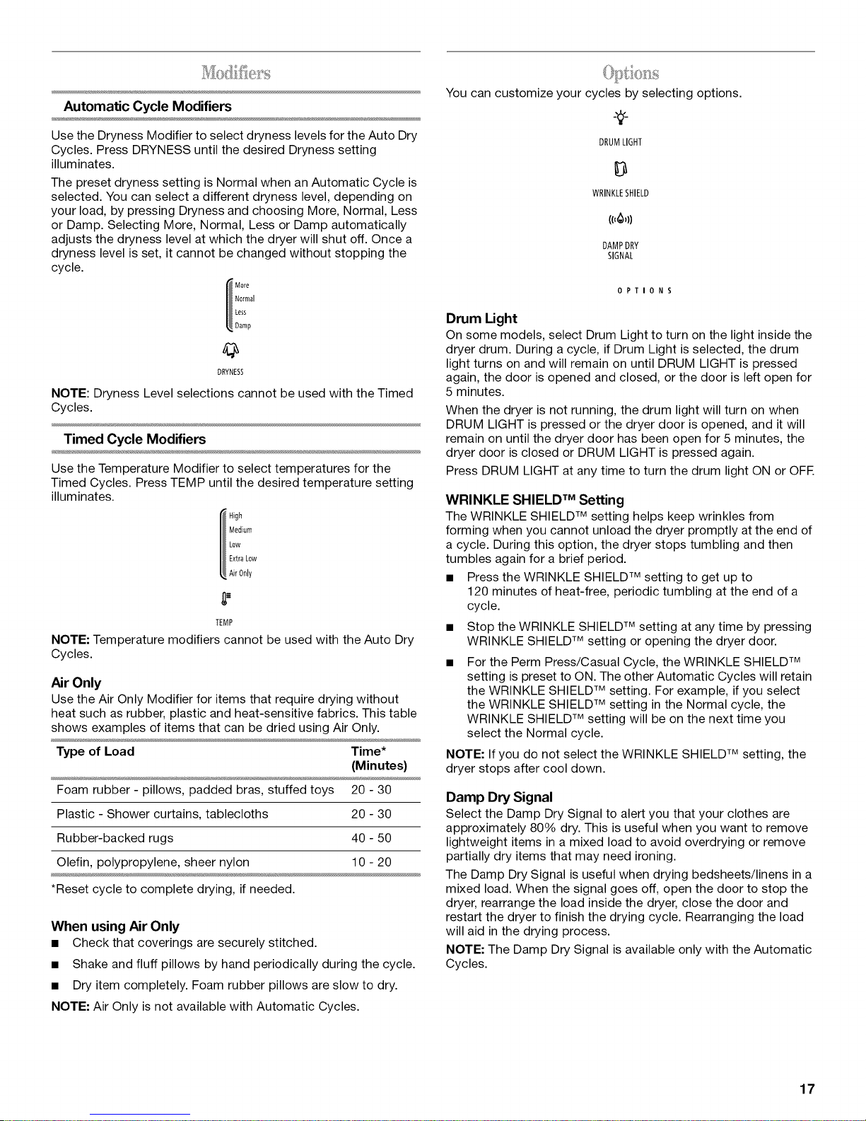
Automatic Cycle Modifiers
You can customize your cycles by selecting options.
Use the Dryness Modifier to select dryness levels for the Auto Dry
Cycles. Press DRYNESS until the desired Dryness setting
illuminates.
The preset dryness setting is Normal when an Automatic Cycle is
selected. You can select a different dryness level, depending on
your load, by pressing Dryness and choosing More, Normal, Less
or Damp. Selecting More, Normal, Less or Damp automatically
adjusts the dryness level at which the dryer will shut off. Once a
dryness level is set, it cannot be changed without stopping the
cycle.
DRYNESS
NOTE: Dryness Level selections cannot be used with the Timed
Cycles.
Timed Cycle Modifiers
Use the Temperature Modifier to select temperatures for the
Timed Cycles. Press TEMP until the desired temperature setting
illuminates.
TEMP
NOTE: Temperature modifiers cannot be used with the Auto Dry
Cycles.
Air Only
Use the Air Only Modifier for items that require drying without
heat such as rubber, plastic and heat-sensitive fabrics. This table
shows examples of items that can be dried using Air Only.
Type of Load Time*
(Minutes)
Foam rubber - pillows, padded bras, stuffed toys 20 - 30
Plastic - Shower curtains, tablecloths 20 - 30
Rubber-backed rugs
Olefin, polypropylene, sheer nylon
40 - 50
10 -20
*Reset cycle to complete drying, if needed.
When using Air Only
• Check that coverings are securely stitched.
• Shake and fluff pillows by hand periodically during the cycle.
• Dry item completely. Foam rubber pillows are slow to dry.
NOTE: Air Only is not available with Automatic Cycles.
DRUMLIGHT
WRINKLESHIELD
((,_,))
DAMPDRY
SIGNAL
OPTIONS
Drum Light
On some models, select Drum Light to turn on the light inside the
dryer drum. During a cycle, if Drum Light is selected, the drum
light turns on and will remain on until DRUM LIGHT is pressed
again, the door is opened and closed, or the door is left open for
5 minutes.
When the dryer is not running, the drum light will turn on when
DRUM LIGHT is pressed or the dryer door is opened, and it will
remain on until the dryer door has been open for 5 minutes, the
dryer door is closed or DRUM LIGHT is pressed again.
Press DRUM LIGHT at any time to turn the drum light ON or OFF.
WRINKLE SHIELD TM Setting
The WRINKLE SHIELD TM setting helps keep wrinkles from
forming when you cannot unload the dryer promptly at the end of
a cycle. During this option, the dryer stops tumbling and then
tumbles again for a brief period.
• Press the WRINKLE SHIELD TM setting to get up to
120 minutes of heat-free, periodic tumbling at the end of a
cycle.
• Stop the WRINKLE SHIELD TM setting at any time by pressing
WRINKLE SHIELD TM setting or opening the dryer door.
• For the Perm Press/Casual Cycle, the WRINKLE SHIELD TM
setting is preset to ON. The other Automatic Cycles will retain
the WRINKLE SHIELD TM setting. For example, if you select
the WRINKLE SHIELD TM setting in the Normal cycle, the
WRINKLE SHIELD TM setting will be on the next time you
select the Normal cycle.
NOTE: If you do not select the WRINKLE SHIELD TM setting, the
dryer stops after cool down.
Damp Dry Signal
Select the Damp Dry Signal to alert you that your clothes are
approximately 80% dry. This is useful when you want to remove
lightweight items in a mixed load to avoid overdrying or remove
partially dry items that may need ironing.
The Damp Dry Signal is useful when drying bedsheets/linens in a
mixed load. When the signal goes off, open the door to stop the
dryer, rearrange the load inside the dryer, close the door and
restart the dryer to finish the drying cycle. Rearranging the load
will aid in the drying process.
NOTE: The Damp Dry Signal is available only with the Automatic
Cycles.
17
End of Cycle Signal
The End of Cycle Signal produces an audible sound when the
drying cycle is finished. Promptly removing clothes at the end of
the cycle reduces wrinkling.
Press END OF CYCLE SIGNAL until the desired volume (Loud,
Soft or Off) is selected.
ENDOFCYCLE
SIGNAL
NOTE: When the WRINKLE SHIELD TM setting is selected and the
End of Cycle Signal is on, a tone sounds every 5 minutes until the
clothes are removed, or the WRINKLE SHIELD TM setting ends.
You can change Automatic and Timed Cycles, Modifiers and
Options anytime before pressing Start.
• Three short tones sound if an unavailable combination is
selected. The last selection will not be accepted.
Changing Cycles after pressing Start
1. Press PAUSE/CANCEL twice.
2. Select the desired cycle and options.
3. Press START. The dryer starts at the beginning of the new
cycle.
NOTE: If you do not press Start within 5 minutes of selecting the
cycle, the dryer automatically shuts off.
Changing Modifiers and Options after pressing Start
You can change an Option or Modifier anytime before the
selected Option or Modifier begins.
1. Press PAUSE/CANCEL once.
2. Select the new Option and/or Modifiers.
3. Press START to continue the cycle.
NOTE: If you happen to press PAUSE/CANCEL twice, the
program clears and your dryer shuts down. Restart the selection
process.
3. To select a new drying setting, press the DRYNESS button
again until the desired drying setting is shown.
NOTE: While cycling through the settings, the current setting
will not flash, but the other settings will flash.
4. Press START to save the drying setting.
5. The drying setting you selected will become your new preset
drying setting for all Auto Dry cycles.
Use the Drying Rack to dry items such as sweaters and pillows
without tumbling. The drum turns, but the drying rack does not
move.
If your model does not have a drying rack, you may be able to
purchase one for your model. To find out whether your model
allows drying rack usage and for information on ordering, please
refer to the front page of the manual or contact the dealer from
whom you purchased your dryer.
NOTE: The drying rack must be removed for normal tumbling. Do
not use the automatic cycle with the drying rack.
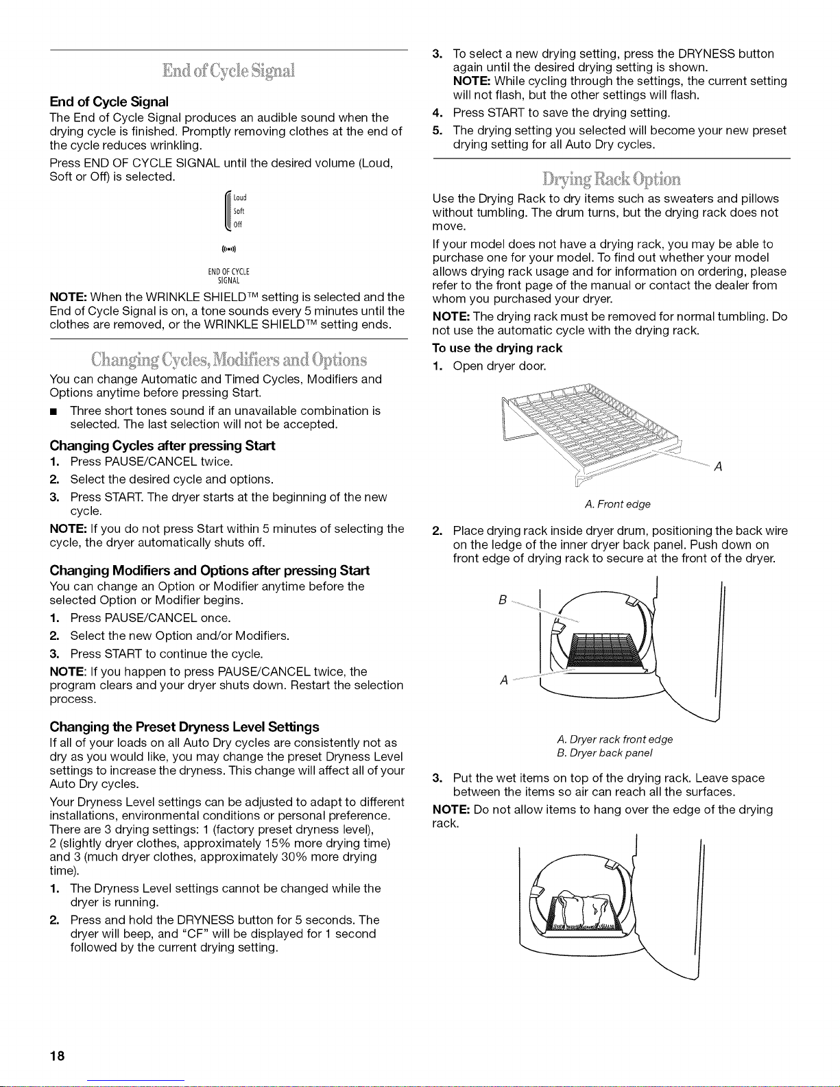
To use the drying rack
1. Open dryer door.
A
A. Front edge
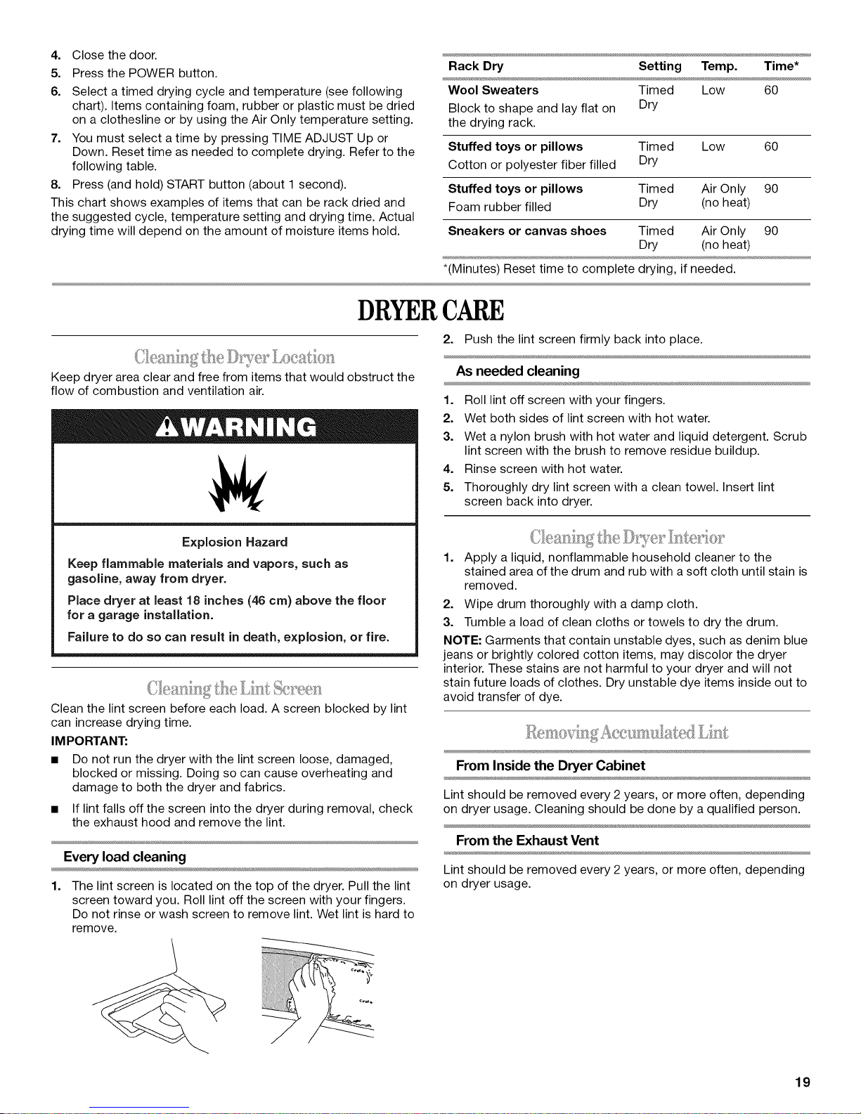
2,
Place drying rack inside dryer drum, positioning the back wire
on the ledge of the inner dryer back panel. Push down on
front edge of drying rack to secure at the front of the dryer.
I
B
Changing the Preset Dryness Level Settings
If all of your loads on all Auto Dry cycles are consistently not as
dry as you would like, you may change the preset Dryness Level
settings to increase the dryness. This change will affect all of your
Auto Dry cycles.
Your Dryness Level settings can be adjusted to adapt to different
installations, environmental conditions or personal preference.
There are 3 drying settings: 1 (factory preset dryness level),
2 (slightly dryer clothes, approximately 15% more drying time)
and 3 (much dryer clothes, approximately 30% more drying
time).
1. The Dryness Level settings cannot be changed while the
dryer is running.
2. Press and hold the DRYNESS button for 5 seconds. The
dryer will beep, and "CF" will be displayed for 1 second
followed by the current drying setting.
18
A. Dryer rack front edge
B. Dryer back panel
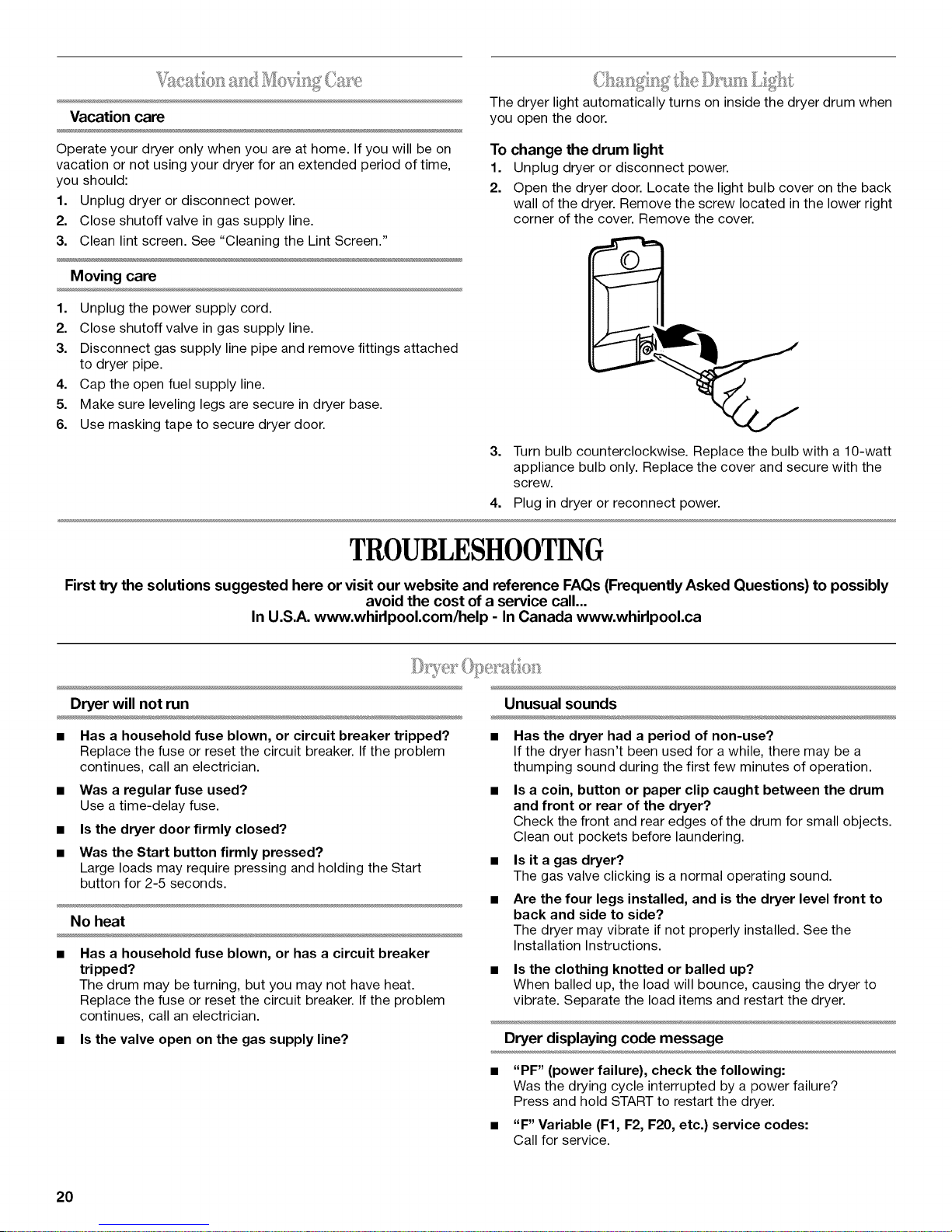
3. Put the wet items on top of the drying rack. Leave space
between the items so air can reach all the surfaces.
NOTE: Do not allow items to hang over the edge of the drying
rack.
I
4. Close the door.
5. Press the POWER button.
6. Select a timed drying cycle and temperature (see following
chart). Items containing foam, rubber or plastic must be dried
on a clothesline or by using the Air Only temperature setting.
7. You must select a time by pressing TIME ADJUST Up or
Down. Reset time as needed to complete drying. Refer to the
following table.
8. Press (and hold) START button (about 1 second).
This chart shows examples of items that can be rack dried and
the suggested cycle, temperature setting and drying time. Actual
drying time will depend on the amount of moisture items hold.
DRYERCARE
Rack Dry Setting Temp. Time*
Wool Sweaters Timed Low 60
Block to shape and lay flat on Dry
the drying rack.
Stuffed toys or pillows Timed Low 60
Cotton or polyester fiber filled Dry
Stuffed toys or pillows Timed Air Only 90
Foam rubber filled Dry (no heat)
Sneakers or canvas shoes Timed Air Only 90
Dry (no heat)
*(Minutes) Reset time to complete drying, if needed.
2. Push the lint screen firmly back into place.
Keep dryer area clear and free from items that would obstruct the
flow of combustion and ventilation air.
Explosion Hazard
Keep flammable materials and vapors, such as
gasoline, away from dryer.
Place dryer at least 18 inches (46 cm) above the floor
for a garage installation.
Failure to do so can result in death, explosion, or fire.
(;IJ_lil_llI__ Ii,I (:_III]
Clean the lint screen before each load. A screen blocked by lint
can increase drying time.
IMPORTANT:
• Do not run the dryer with the lint screen loose, damaged,
blocked or missing. Doing so can cause overheating and
damage to both the dryer and fabrics.
• If lint falls off the screen into the dryer during removal, check
the exhaust hood and remove the lint.
Every load cleaning
1. The lint screen is located on the top of the dryer. Pull the lint
screen toward you. Roll lint off the screen with your fingers.
Do not rinse or wash screen to remove lint. Wet lint is hard to
remove.
I.l/<i I _>=_i I Jl
As needed cleaning
1. Roll lint off screen with your fingers.
2. Wet both sides of lint screen with hot water.
3. Wet a nylon brush with hot water and liquid detergent. Scrub
lint screen with the brush to remove residue buildup.
4. Rinse screen with hot water.
5. Thoroughly dry lint screen with a clean towel. Insert lint
screen back into dryer.
l. lelllllll= _ I .... " = °,
1. Apply a liquid, nonflammable household cleaner to the
stained area of the drum and rub with a soft cloth until stain is
removed.
2. Wipe drum thoroughly with a damp cloth.
3. Tumble a load of clean cloths or towels to dry the drum.
NOTE: Garments that contain unstable dyes, such as denim blue
jeans or brightly colored cotton items, may discolor the dryer
interior. These stains are not harmful to your dryer and will not
stain future loads of clothes. Dry unstable dye items inside out to
avoid transfer of dye.
From Inside the Dryer Cabinet
Lint should be removed every 2 years, or more often, depending
on dryer usage. Cleaning should be done by a qualified person.
From the Exhaust Vent
Lint should be removed every 2 years, or more often, depending
on dryer usage.
19
Vacation care
The dryer light automatically turns on inside the dryer drum when
you open the door.
Operate your dryer only when you are at home. If you will be on
vacation or not using your dryer for an extended period of time,
you should:
1. Unplug dryer or disconnect power.
2. Close shutoff valve in gas supply line.
3. Clean lint screen. See "Cleaning the Lint Screen."
Moving care
1. Unplug the power supply cord.
2. Close shutoff valve in gas supply line.
3. Disconnect gas supply line pipe and remove fittings attached
to dryer pipe.
4. Cap the open fuel supply line.
5. Make sure leveling legs are secure in dryer base.
6. Use masking tape to secure dryer door.
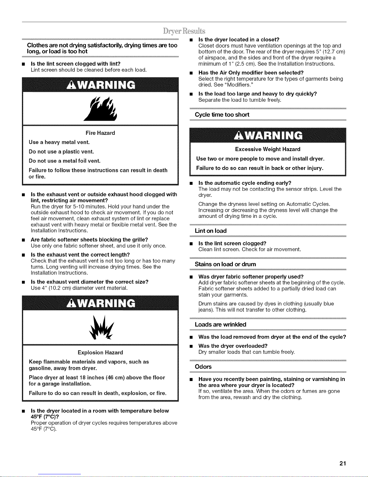
To change the drum light
1. Unplug dryer or disconnect power.
2. Open the dryer door. Locate the light bulb cover on the back
wall of the dryer. Remove the screw located in the lower right
corner of the cover. Remove the cover.
3. Turn bulb counterclockwise. Replace the bulb with a lO-watt
appliance bulb only. Replace the cover and secure with the
screw.
4. Plug in dryer or reconnect power.
TROUBLESHOOTING
Firsttry the solutions suggested here or visit our website and reference FAQs (Frequently Asked Questions) to possibly
In U.S.A. www.whirlpool.com/help - In Canada www.whirlpool.ca
avoid the cost of a service call...
Dryer will not run
• Has a household fuse blown, or circuit breaker tripped?
Replace the fuse or reset the circuit breaker. If the problem
continues, call an electrician.
• Was a regular fuse used?
Use a time-delay fuse.
• Is the dryer door firmly closed?
• Was the Start button firmly pressed?
Large loads may require pressing and holding the Start
button for 2-5 seconds.
No heat
• Has a household fuse blown, or has a circuit breaker
tripped?
The drum may be turning, but you may not have heat.
Replace the fuse or reset the circuit breaker. If the problem
continues, call an electrician.
• Is the valve open on the gas supply line?
Unusual sounds
• Has the dryer had a period of non-use?
If the dryer hasn't been used for a while, there may be a
thumping sound during the first few minutes of operation.
• Is a coin, button or paper clip caught between the drum
and front or rear of the dryer?
Check the front and rear edges of the drum for small objects.
Clean out pockets before laundering.
• Is it a gas dryer?
The gas valve clicking is a normal operating sound.
• Are the four legs installed, and is the dryer level front to
back and side to side?
The dryer may vibrate if not properly installed. See the
Installation Instructions.
Is the clothing knotted or balled up?
When balled up, the load will bounce, causing the dryer to
vibrate. Separate the load items and restart the dryer.
Dryer displaying code message
• "PF" (power failure), check the following:
Was the drying cycle interrupted by a power failure?
Press and hold START to restart the dryer.
• "F" Variable (F1, F2, F20, etc.) service codes:
Call for service.
20
Clothes are not drying satisfactorily, drying times are too
long, or load is too hot
• Is the lint screen clogged with lint?
Lint screen should be cleaned before each load.
Fire Hazard
Use a heavy metal vent.
Do not use a plastic vent.
Do not use a metal foil vent.
Failure to follow these instructions can result in death
or fire.
Is the exhaust vent or outside exhaust hood clogged with
lint, restricting air movement?
Run the dryer for 5-10 minutes. Hold your hand under the
outside exhaust hood to check air movement. If you do not
feel air movement, clean exhaust system of lint or replace
exhaust vent with heavy metal or flexible metal vent. See the
Installation Instructions.
Are fabric softener sheets blocking the grille?
Use only one fabric softener sheet, and use it only once.
Is the exhaust vent the correct length?
Check that the exhaust vent is not too long or has too many
turns. Long venting will increase drying times. See the
Installation Instructions.
Is the exhaust vent diameter the correct size?
Use 4" (10.2 cm) diameter vent material.
• Is the dryer located in a closet?
Closet doors must have ventilation openings at the top and
bottom of the door. The rear of the dryer requires 5" (12.7 cm)
of airspace, and the sides and front of the dryer require a
minimum of 1" (2.5 cm). See the Installation Instructions.
• Has the Air Only modifier been selected?
Select the right temperature for the types of garments being
dried. See "Modifiers."
• Is the load too large and heavy to dry quickly?
Separate the load to tumble freely.
Cycle time too short
Excessive Weight Hazard
Use two or more people to move and install dryer.
Failure to do so can result in back or other injury.
• Is the automatic cycle ending early?
The load may not be contacting the sensor strips. Level the
dryer.
Change the dryness level setting on Automatic Cycles.
Increasing or decreasing the dryness level will change the
amount of drying time in a cycle.
Lint on load
• Is the lint screen clogged?
Clean lint screen. Check for air movement.
Stains on load or drum
• Was dryer fabric softener properly used?
Add dryer fabric softener sheets at the beginning of the cycle.
Fabric softener sheets added to a partially dried load can
stain your garments.
Drum stains are caused by dyes in clothing (usually blue
jeans). This will not transfer to other clothing.
Explosion Hazard
Keep flammable materials and vapors, such as
gasoline, away from dryer.
Place dryer at least 18 inches (46 crn) above the floor
for a garage installation.
Failure to do so can result in death, explosion, or fire.
Is the dryer located in a room with temperature below
45°F (7°C)?
Proper operation of dryer cycles requires temperatures above
45°F (7°C).
Loads are wrinkled
• Was the load removed from dryer at the end of the cycle?
• Was the dryer overloaded?
Dry smaller loads that can tumble freely.
Odors
Have you recently been painting, staining or varnishing in
the area where your dryer is located?
If so, ventilate the area. When the odors or fumes are gone
from the area, rewash and dry the clothing.
21
ASSISTANCEORSERVICE
Before calling for assistance or service, please check
"Troubleshooting." It may save you the cost of a service call. If
you still need help, follow the instructions below.
When calling, please know the purchase date and the complete
model and serial number of your appliance. This information will
help us to better respond to your request.
If you need replacement parts
If you need to order replacement parts, we recommend that you
only use FSP®factory specified parts. These parts will fit right
and work right because they are made with the same precision
used to build every new WHIRLPOOL ®appliance.
To locate FSP®replacement parts in your area:
In the U.S.A., call the Customer eXperience Center at
1-800-253-1301, or your nearest designated service center.
In Canada, call 1-800-807-6777, or your nearest designated
service center.
Call the Whirlpool Customer eXperience Center toll free:
1-800-253-1301 or visit us at www.whirlpool.com.
Our consultants provide assistance with:
Features and specifications on our full line of appliances.
Installation information.
Use and maintenance procedures.
Accessory and repair parts sales.
Specialized customer assistance (Spanish speaking, hearing
impaired, limited vision, etc.).
Referrals to local dealers, repair parts distributors, and
service companies. Whirlpool designated service technicians
are trained to fulfill the product warranty and provide after-
warranty service, anywhere in the United States.
To locate the Whirlpool designated service company inyour
area, you can also look in your telephone directory Yellow
Pages.
For further assistance
If you need further assistance, you can write to Whirlpool
Corporation with any questions or concerns at:
Whirlpool Brand Home Appliances
Customer eXperience Center
553 Benson Road
Benton Harbor, MI 49022-2692
Please include a daytime phone number in your correspondence.
Call the Whirlpool Canada LP Customer Interaction Centre toll
free: 1-800-807-6777 or visit us at www.whirlpool.ca.
Our consultants provide assistance with:
• Use and maintenance procedures
• Accessory and repair parts sales
• Features and specifications on our full line of appliances
• Referrals to local dealers, repair parts distributors, and
service companies. Whirlpool Canada LP designated service
technicians are trained to fulfill the product warranty and
provide after-warranty service anywhere in Canada.
For further assistance
If you need further assistance, you can write to Whirlpool Canada
LP with any questions or concerns at:
Customer Interaction Centre
Whirlpool Canada LP
1901 Minnesota Court
Mississauga, Ontario L5N 3A7
Please include a daytime phone number in your correspondence.
ACCESSORIES
Enhance your dryer with these premium accessories.
For more high-quality items or to order, call 1-800-901-2042, or
visit us at www.whirlpool.com/accessories. In Canada,call
1-800-807-6777, or visit us at www.whirlpoolparts.ca.
Part Accessory
Number
20-48KITRC 4 ft (1.2 m) gas line dryer connector
PT220L
PT400L
PT600L
4210463
31682
1903WH
49572
W10071550A
installation kit
4 ft (1.2 m) dryer cord, 3-wire, 30 amp
4 ft (1.2 m) dryer cord, 4-wire, 30 amp
6 ft (1.8 m) dryer cord, 4-wire, 30 amp
Dryer vent lint brush
All-purpose appliance cleaner
Laundry supply storage cart
LP gas conversion kit
Dryer Rack
Accessories U.S.A.
To order accessories, call the Whirlpool Customer eXperience
Center toll free at 1-800-442-9991 and follow the menu prompts.
Or visit our website at www.whirlpool.com.
22
WHIRLPOOLCORPORATIONMAJORAPPLIANCEWARRANTY
ONE YEAR LIMITED WARRANTY
For one year from the date of purchase, when this major appliance is operated and maintained according to instructions attached to or
furnished with the product, Whirlpool Corporation or Whirlpool Canada LP (hereafter "Whirlpool") will pay for Factory Specified Parts
and repair labor to correct defects in materials or workmanship. Service must be provided by a Whirlpool designated service company.
This limited warranty applies only when the major appliance is used in the country in which it was purchased.
ITEMS WHIRLPOOL WILL NOT PAY FOR
1. Service calls to correct the installation of your major appliance, to instruct you how to use your major appliance, to replace or repair
house fuses or to correct house wiring or plumbing.
2. Service calls to repair or replace appliance light bulbs, air filters or water filters. Those consumable parts are excluded from warranty
coverage.
3. Repairs when your major appliance is used for other than normal, single-family household use.
4. Damage resulting from accident, alteration, misuse, abuse, fire, flood, acts of God, improper installation, installation not in
accordance with electrical or plumbing codes, or use of products not approved by Whirlpool.
5. Any food loss due to refrigerator or freezer product failures.
6. Replacement parts or repair labor costs for units operated outside the United States or Canada.
7. Pickup and delivery. This major appliance is designed to be repaired in the home.
8. Repairs to parts or systems resulting from unauthorized modifications made to the appliance.
9. Expenses for travel and transportation for product service in remote locations.
10. The removal and reinstallation of your appliance if it is installed in an inaccessible location or is not installed in accordance with
published installation instructions.
11. Replacement parts or repair labor costs when the major appliance is used in a country other than the country in which it was
purchased.
DISCLAIMER OF IMPLIED WARRANTIES; LIMITATION OF REMEDIES
CUSTOMER'S SOLE AND EXCLUSIVE REMEDY UNDER THIS LIMITED WARRANTY SHALL BE PRODUCT REPAIR AS PROVIDED
HEREIN. IMPLIED WARRANTIES, INCLUDING WARRANTIES OF MERCHANTABILITY OR FITNESS FOR A PARTICULAR PURPOSE,
ARE LIMITED TO ONE YEAR OR THE SHORTEST PERIOD ALLOWED BY LAW. WHIRLPOOL SHALL NOT BE LIABLE FOR
INCIDENTAL OR CONSEQUENTIAL DAMAGES. SOME STATES AND PROVINCES DO NOT ALLOW THE EXCLUSION OR LIMITATION
OF INCIDENTAL OR CONSEQUENTIAL DAMAGES, OR LIMITATIONS ON THE DURATION OF IMPLIED WARRANTIES OF
MERCHANTABILITY OR FITNESS, SO THESE EXCLUSIONS OR LIMITATIONS MAY NOT APPLY TO YOU. THIS WARRANTY GIVES
YOU SPECIFIC LEGAL RIGHTS AND YOU MAY ALSO HAVE OTHER RIGHTS, WHICH VARY FROM STATE TO STATE OR PROVINCE
TO PROVINCE.
Outside the 50 United States and Canada, this warranty does not apply. Contact your authorized Whirlpool dealer to determine if
another warranty applies.
If you need service, first see the "Troubleshooting" section of the Use & Care Guide. After checking "Troubleshooting," additional help
can be found by checking the "Assistance or Service" section or by calling Whirlpool. In the U.S.A., call 1-800-253-1301. In Canada,
call 1-800-807-6777. 12/05
Keep this book and your sales slip together for future
reference. You must provide proof of purchase or installation
date for in-warranty service.
Write down the following information about your major appliance
to better help you obtain assistance or service if you ever need it.
You will need to know your complete model number and serial
number. You can find this information on the model and serial
number label located on the product.
Dealer name
Address
Phone number
Model number
Serial number
Purchase date
23
# # #
SECURITEDELASECHEUSE
Votre securite et celle des autres est tres importante.
Nous donnons de nombreux messages de s_curit_ importants dans ce manuel et sur votre appareil m_nager. Assurez-vous de
toujours lire tousles messages de s_curit_ et de vous y conformer.
Ce symbole d'alerte de s_curit_ vous signale les dangers potentiels de d_c_s et de blessures graves & vous
et & d'autres.
Voici le symbole d'alerte de s_curit&
Tousles messages de s_curit_ suivront le symbole d'alerte de s_curit_ et le mot "DANGER" ou
"AVERTISSEMENT". Ces mots signifient •
Risque possible de d_cbs ou de blessure grave si vous ne
suivez pas imm_diatement les instructions.
Risque possible de d_cbs ou de blessure grave si vous
ne suivez pas les instructions.
Tousles messages de s_curit_ vous diront quel est le danger potentiel et vous disent comment r_duire le risque de blessure et
ce qui peut se produire en cas de non-respect des instructions.
AVERTISSEMENT • Pour votre securite, les renseignements dans ce manuel doivent
etre observes pour reduire au minimum les risques d'incendie ou d'explosion ou pour
eviter des dommages au produit, des blessures ou un deces.
- Ne pas entreposer ou utiliser de ressence ou d'autres vapeurs ou liquides
inflammables a proximite de cet appareil ou de tout autre appareil electromenager.
-QUE FAIRE DANS LE CAS D'UNE ODEUR DE GAZ :
• Ne pas tenter d'allumer un appareil.
• Ne pas toucher a un commutateur electrique; ne pas utiliser le telephone se trouvant
sur les lieux.
• I_vacuer tous les gens de la piece, de I'edifice ou du quartier.
• Appeler immediatement le fournisseur de gaz d'un telephone voisin. Suivre ses
instructions.
• .&.defaut de joindre votre fournisseur de gaz, appeler les pompiers.
- L'installation et rentretien doivent etre effectues par un installateur qualifie, une
agence de service ou le fournisseur de gaz.
24
IMPORTANTES INSTRUCTIONS DE SECURJTE
AMERT_SSE_V_ ENT • Pour reduire le risque d'incendie, de choc electrique ou de blessure Iors de I'utilisation de
la secheuse, il convient d'observer certaines precautions el6mentaires dont les suivantes :
[] Lire toutes les instructions avant d'utiliser la secheuse.
[] Ne pas placer des articles exposes aux huiles de cuisson
dans votre secheuse. Les articles contamines par des
huiles de cuisson peuvent contribuer &une reaction
chimique qui pourrait causer & la charge de s'enflammer.
[] Ne pas faire secher dans la machine des articles qui ont
deja et6 nettoyes, laves, imbibes, ou taches d'essence,
de solvants pour nettoyage & sec, d'autres substances
inflammables, ou de substances explosives puisqu'elles
degagent des vapeurs qui peuvent provoquer un
incendie ou une explosion.
[] Ne pas permettre & des enfants de jouer sur ou &
I'interieur de la secheuse. Une surveillance etroite est
necessaire Iorsque la secheuse est utilisee pres d'eux.
[] Avant d'enlever la secheuse du service ou la jeter, enlever
la porte du compartiment de sechage.
[] Ne pas mettre la main dans la secheuse si le tambour est
en mouvement.
[] Ne pas installer ni entreposer la secheuse ou elle sera
exposee aux intemperies.
[] Ne pas jouer avec les commandes.
[] Ne pas reparer ni remplacer une piece de la secheuse ou
essayer d'en faire I'entretien & moins d'une recommandation
specifique dans le guide d'utlilisation et d'entretien, ou
publiee dans les instructions de reparation par I'utilisateur
que vous comprenez et pouvez executer avec competence.
[] Ne pas utiliser un produit assouplissant de tissu ou des
produits pour eliminer la statique & moins qu'ils ne soient
recommandes par le fabricant du produit assouplissant de
tissu ou du produit.
[] Ne pas utiliser la chaleur pour faire secher des articles
fabriques avec du caoutchouc mousse ou des materiaux
semblables.
[] Nettoyer le filtre & charpie avant et apr_s chaque charge.
[] Ne pas laisser la charpie, la poussiere, ou la salete
s'accumuler autour du systeme d'evacuation ou autour de
I'appareil.
[] Un nettoyage periodique de I'interieur de la secheuse et du
conduit d'evacuation doit _tre effectue par une personne
qualifiee.
[] Voir les instructions d'installation pour les exigences de
liaison de I'appareil &la terre.
CONSERVEZ CES INSTRUCTIONS
IMPORTANT : L'installation du gaz dolt se conformer aux codes Iocaux, ou en I'absence de codes Iocaux, au code canadien
d'installation B149.1 du gaz naturel ou du propane.
La secheuse dolt _tre electriquement reliee & la terre conformement aux codes Iocaux, ou en I'absence de codes Iocaux, au Code
canadien de I'electricit6, CSA C22.1.
25
INSTRUCTIONSD'INSTALLATION
.... ?6ces
Rassembler les outils et pieces necessaires avant de commencer
I'installation. Lire et suivre les instructions fournies avec les outils
indiques ici.
• Cle a tuyau de 8" ou 10" •
• Cle& molette de 8" ou 10" •
(pour le raccordement au
gaz) •
• Tournevis a lame plate
• Cle &molette avec •
ouverture jusqu'&
1" (2,5 cm) ou cle & douille
hexagonale (pour ajuster
les pieds de la secheuse)
• Niveau •
• Tourne-ecrou ou cle
douille de 1¼,,
Couteau
Clapets d'evacuation
Compose d'etancheite
des tuyauteries resistant
au gaz de petrole liquefi6
Pistolet & calfeutrage et
compose de calfeutrage
(pour I'installation d'un
nouveau circuit
d'evacuation)
Pince
Risque d'explosion
Garder les matieres et les vapeurs inflammables, telle
que I'essence, loin de la s6cheuse.
Placer la s6cheuse au moins 46 cm (18 po) au=dessus
du plancher pour une installation darts un garage.
Le non=respect de ces instructions peut causer
un d6ces, une explosion ou un incendie.
Pi_ces fournies :
Retirer le sachet de pieces du tambour de la secheuse. Verifier
que toutes les pieces de la liste sont presentes.
4pieds de nivellement
Pi_ces necessaires :
Consulter les codes Iocaux et le fournisseur de gaz, verifier
I'alimentation en gaz existante, I'alimentation electrique et le
circuit d'evacuation, et lire les sections "Specifications
electriques", "Alimentation en gaz" et "Exigences concernant
I'evacuation" avant d'acheter les pieces necessaires.
Les installations pour maison mobile necessitent des pieces
particulieres (voir liste ci-dessous) qui peuvent 6tre commandees
en appelant le marchand chez qui vous avez achete votre
secheuse. Pour des informations sur la commande, veuillez vous
referer & la section "Assistance ou service". Vous pouvez
egalement contacter le marchand chez qui vous avez achete
votre secheuse.
• Trousse d'installation pour maison mobile. Demander le
numero de piece 346764.
• Systeme d'evacuation en metal.
II vous faudra
• Un emplacement permettant une evacuation appropriee. Voir
"Exigences concernant I'evacuation".
• Un circuit separe de 30 amperes.
• Une prise electrique avec liaison & la terre situee a moins de
2 pi (61 cm) de I'un des c6tes de la secheuse. Voir
"Specifications electriques".
• Un plancher robuste capable de supporter un poids total
(secheuse et charge) de 200 Ib (90,7 kg). Le poids combine
d'un appareil voisin dolt egalement 6tre pris en compte.
• Un plancher horizontal avec une pente maximale de
1" (2,5 cm) sous I'ensemble de la secheuse.
Ne pas faire fonctionner la secheuse &des temperatures
inferieures & 45°F (7°C). A des temperatures inferieures, la
secheuse risque de ne plus s'arr6ter & lafin d'un programme
automatique. Les temps de sechage risquent alors d'augmenter.
La secheuse ne dolt pas 6tre installee ou remisee dans un endroit
oQ elle sera exposee & I'eau et/ou aux intemperies.
Verifier les reglements Iocaux. Certains codes limitent ou
n'autorisent pas I'installation des secheuses dans un garage, un
placard, une maison mobile ou une chambre & coucher.
Communiquer avec I'inspecteur des b&timents local.
REMARQUE :Aucun autre appareil consommant un combustible
ne dolt 6tre installe dans le m6me placard.
Degagements de separation _ respecter
L'emplacement dolt 6tre assez grand pour permettre d'ouvrir
completement la porte de la secheuse.
26
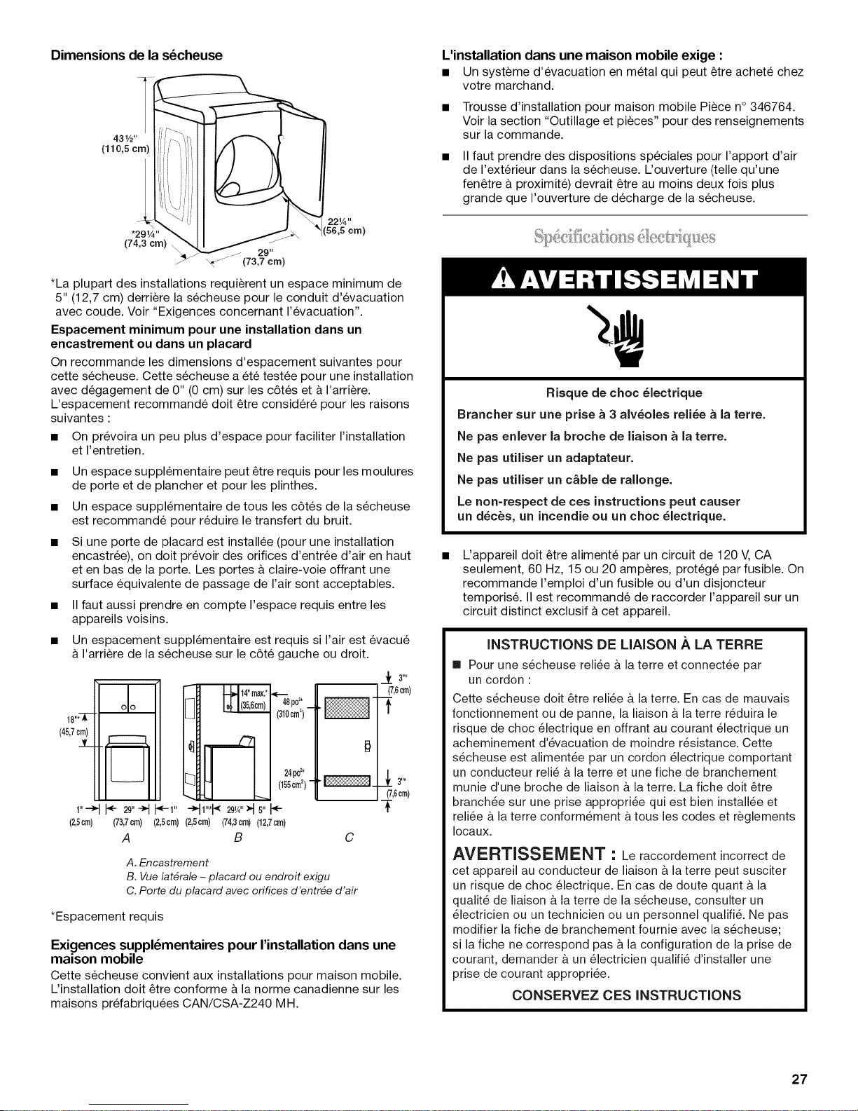
Dimensions de la s_cheuse
*La plupart des installations requierent un espace minimum de
5" (12,7 cm) derriere la secheuse pour le conduit d'evacuation
avec coude. Voir "Exigences concernant I'evacuation".
Espacement minimum pour une installation dans un
encastrement ou dans un placard
On recommande les dimensions d'espacement suivantes pour
cette secheuse. Cette secheuse a et6 testee pour une installation
avec degagement de 0" (0 cm) sur les c6tes et & I'arriere.
L'espacement recommande dolt _tre consider6 pour les raisons
suivantes :
• On prevoira un peu plus d'espace pour faciliter I'installation
et I'entretien.
• Un espace supplementaire peut _tre requis pour les moulures
de porte et de plancher et pour les plinthes.
• Un espace supplementaire de tousles c6tes de la secheuse
est recommande pour reduire le transfert du bruit.
• Si une porte de placard est installee (pour une installation
encastree), on dolt prevoir des orifices d'entree d'air en haut
et en bas de la porte. Les portes a claire-vole offrant une
surface equivalente de passage de I'air sont acceptables.
• II faut aussi prendre en compte I'espace requis entre les
appareils voisins.
• Un espacement supplementaire est requis si I'air est evacu6
& I'arriere de la secheuse sur le c6te gauche ou droit.
_f 3"*
_Sp0 2.
18"*iC
(45,7cm)
__!L
l_J
(310cm2) • _"
2@o2*
(155cm2)- I_1.
1"-_ _ 29"_ _1" _1"*I_ 29,4"_1s"
(2,5cm) (2,5cm) (2,5cm)
*Espacement requis
Exigences suppl_mentaires pour I'installation dans une
maison mobile
Cette secheuse convient aux installations pour maison mobile.
L'installation dolt _tre conforme & la norme canadienne sur les
maisons pr6fabriqu_es CAN/CSA-Z240 MH.
(73,7crn) (74,3crn) (12,7crn)
A B
A. Encastrement
B. Vue lat_rale - placard ou endroit exigu
C. Porte du placard avec orifices d'entr_e d'air
(7,6cm)
#
___ 3"*
(7,6cm)
-[
C
L'installation dans une maison mobile exige :
• Un systeme d'evacuation en metal qui peut _tre achete chez
votre marchand.
• Trousse d'installation pour maison mobile Piece n° 346764.
Voir la section "Outillage et pieces" pour des renseignements
sur la commande.
II faut prendre des dispositions speciales pour I'apport d'air
de I'exterieur dans la secheuse. L'ouverture (telle qu'une
fen_tre a proximite) devrait _tre au moins deux fois plus
grande que I'ouverture de decharge de la secheuse.
Risque de choc _lectrique
Brancher sur une prise a 3 alv_oles reli_e a Jaterre.
Ne pas enlever la broche de liaison a la terre.
Ne pas utiliser un adaptateur.
Ne pas utiliser un c&ble de rallonge.
Le non=respect de ces instructions peut causer
un d_c_s, un incendie ou un choc _lectrique.
L'appareil dolt _tre alimente par un circuit de 120 V, CA
seulement, 60 Hz, 15 ou 20 amperes, protege par fusible. On
recommande I'emploi d'un fusible ou d'un disjoncteur
temporis& II est recommande de raccorder I'appareil sur un
circuit distinct exclusif & cet appareil.
INSTRUCTIONS DE LIAISON A LA TERRE
[] Pour une s_cheuse reli_e & la terre et connect_e par
un cordon :
Cette s_cheuse dolt @re reli_e & la terre. En cas de mauvais
fonctionnement ou de panne, la liaison & la terre r_duira le
risque de choc _lectrique en offrant au courant _lectrique un
acheminement d'_vacuation de moindre r_sistance. Cette
s_cheuse est aliment_e par un cordon _lectrique comportant
un conducteur reli_ & la terre et une fiche de branchement
munie d'une broche de liaison & la terre. La fiche dolt @re
branch_e sur une prise appropri_e qui est bien install_e et
reli_e & la terre conform_ment &tousles codes et reglements
Iocaux.
AVERTISSEMENT " Le raccordement incorrect de
cet appareil au conducteur de liaison & la terre peut susciter
un risque de choc _lectrique. En cas de doute quant & la
qualit_ de liaison & la terre de la s_cheuse, consulter un
_lectricien ou un technicien ou un personnel qualifi& Ne pas
modifier la fiche de branchement fournie avec la s_cheuse;
si la fiche ne correspond pas &la configuration de la prise de
courant, demander &un _lectricien qualifi_ d'installer une
prise de courant appropri_e.
CONSERVEZ CES INSTRUCTIONS
27
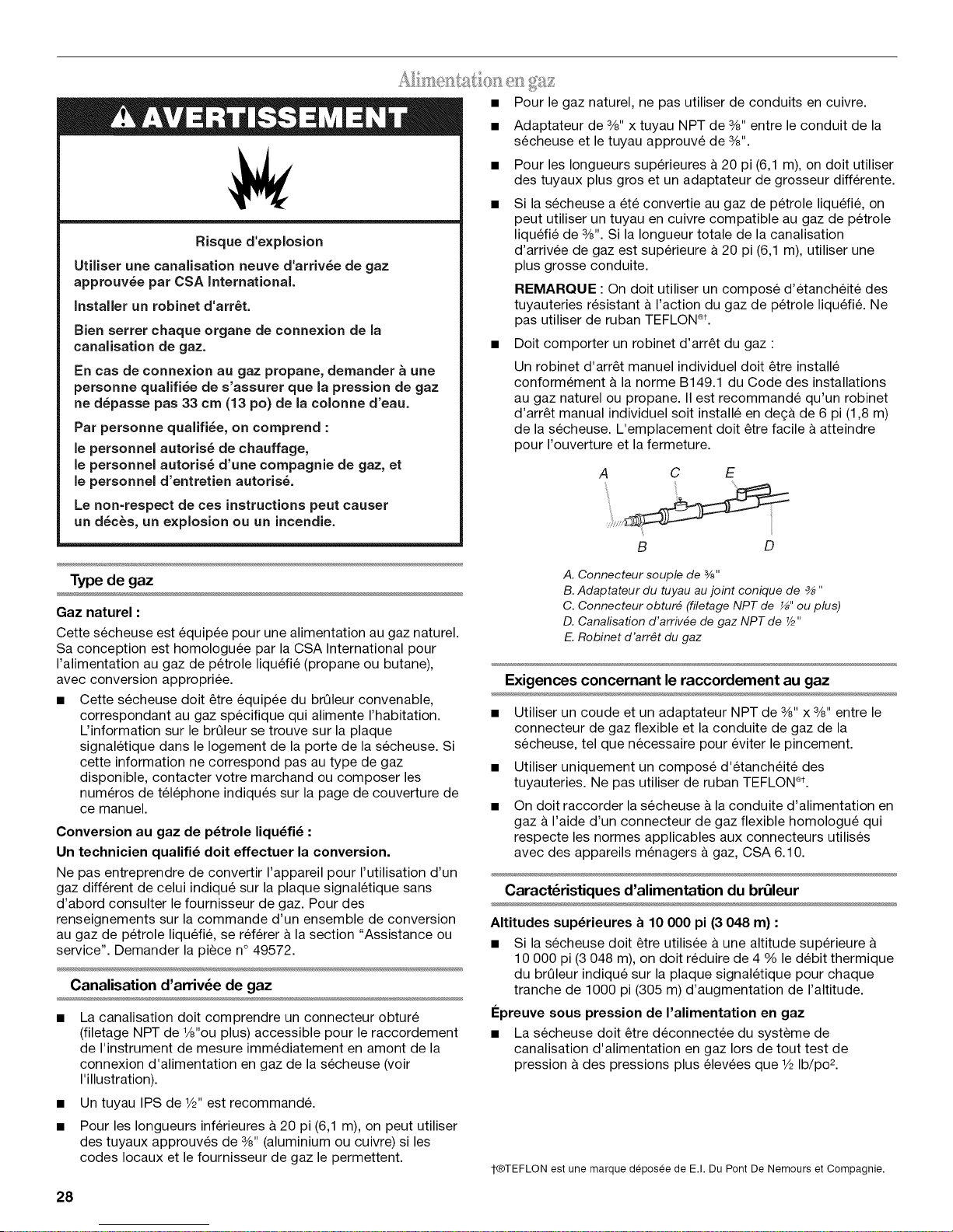
Risque d'explosion
Utiliser une canalisation neuve d'arriv_e de gaz
approuv_e par CSA International.
installer un robinet d'arr_t.
Bien serrer chaque organe de connexion de la
canalisation de gaz.
En cas de connexion au gaz propane, demander a une
personne qualifi_e de s'assurer que la pression de gaz
ne d_passe pas 33 cm (13 po) de la colonne d'eau.
Par personne qualifi_e, on comprend :
le personnel autoris_ de chauffage,
le personnel autoris_ d'une compagnie de gaz, et
le personnel d'entretien autoris&
Le non=respect de ces instructions peut causer
un d_c_s, un explosion ou un incendie.
• Pour le gaz naturel, ne pas utiliser de conduits en cuivre.
• Adaptateur de 3/8"x tuyau NPT de 3/8"entre le conduit de la
secheuse et le tuyau approuve de 3/8".
• Pour les Iongueurs superieures & 20 pi (6,1 m), on doit utiliser
des tuyaux plus gros et un adaptateur de grosseur differente.
• Si la secheuse a et6 convertie au gaz de petrole liqu6fi6, on
peut utiliser un tuyau en cuivre compatible au gaz de petrole
liqu6fi6 de 3/8".Si la Iongueur totale de la canalisation
d'arrivee de gaz est superieure a 20 pi (6,1 m), utiliser une
plus grosse conduite.
REMARQUE : On doit utiliser un compose d'etanch6it6 des
tuyauteries resistant a I'action du gaz de petrole liqu6fi& Ne
pas utiliser de ruban TEFLON ®t.
• Doit comporter un robinet d'arr_t du gaz :
Un robinet d'arr_t manuel individuel doit _tre installe
conformement & la norme B149.1 du Code des installations
au gaz naturel ou propane. II est recommande qu'un robinet
d'arr_t manual individuel soit installe en de(_&de 6 pi (1,8 m)
de la secheuse. L'emplacement doit _tre facile a atteindre
pour I'ouverture et la fermeture.
A C E
B D
Type de gaz
Gaz naturel :
Cette secheuse est equip6e pour une alimentation au gaz naturel.
Sa conception est homologuee par la CSA International pour
I'alimentation au gaz de petrole liqu6fi6 (propane ou butane),
avec conversion appropriee.
• Cette secheuse doit _tre equip6e du brQleur convenable,
correspondant au gaz specifique qui alimente I'habitation.
L'information sur le brQleur se trouve sur la plaque
signaletique dans le Iogement de la porte de la secheuse. Si
cette information ne correspond pas au type de gaz
disponible, contacter votre marchand ou composer les
numeros de tel6phone indiqu6s sur la page de couverture de
ce manuel.
Conversion au gaz de p_trole liqu_fi_ :
Un technicien qualifi_ dolt effectuer la conversion.
Ne pas entreprendre de convertir I'appareil pour I'utilisation d'un
gaz different de celui indiqu6 sur la plaque signaletique sans
d'abord consulter le fournisseur de gaz. Pour des
renseignements sur la commande d'un ensemble de conversion
au gaz de petrole liqu6fi6, se ref6rer & la section "Assistance ou
service". Demander la piece n° 49572.
Canalisation d'arriv6e de gaz
• La canalisation doit comprendre un connecteur obture
(filetage NPT de ½"ou plus) accessible pour le raccordement
de I'instrument de mesure immediatement en amont de la
connexion d'alimentation en gaz de la secheuse (voir
I'illustration).
• Un tuyau IPS de 1/2"est recommand&
• Pour les Iongueurs inferieures a 20 pi (6,1 m), on peut utiliser
des tuyaux approuves de 3/8"(aluminium ou cuivre) si les
codes Iocaux et lefournisseur de gaz le permettent.
28
A. Connecteur souple de %"
B.Adaptateur du tuyau au joint conique de _ "
C. Connecteur obtur_ (filetage NPT de _" ou plus)
D. Canafisation d'arriv_e de gaz NPT de Y2"
E. Robinet d'arr#t du gaz
Exigences concernant le raccordement au gaz
• Utiliser un coude et un adaptateur NPT de 3/8"x 3/8"entre le
connecteur de gaz flexible et la conduite de gaz de la
secheuse, tel que necessaire pour eviter le pincement.
• Utiliser uniquement un compose d'etancheite des
tuyauteries. Ne pas utiliser de ruban TEFLON ®t.
• On doit raccorder la secheuse &la conduite d'alimentation en
gaz & I'aide d'un connecteur de gaz flexible homologu_ qui
respecte les normes applicables aux connecteurs utilises
avec des appareils menagers & gaz, CSA 6.10.
Caract_ristiques d'alimentation du brOleur
Altitudes sup_rieures a 10 000 pi (3 048 m) :
• Si la secheuse doit _tre utilisee &une altitude superieure &
10 000 pi (3 048 m), on doit reduire de 4 % le debit thermique
du brQleur indiqu_ sur la plaque signaletique pour chaque
tranche de 1000 pi (305 m) d'augmentation de I'altitude.
I_preuve sous pression de I'alimentation en gaz
• La secheuse doit _tre deconnectee du systeme de
canalisation d'alimentation en gaz Iors de tout test de
pression & des pressions plus elevees que 1/2Ib/po 2.
¢®TEFLON est une marque deposee de E.I. Du Pont De Nemours et Compagnie.
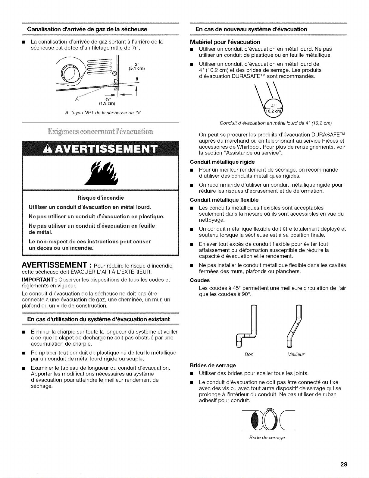
Canalisation d'arriv_e de gaz de la s_cheuse
En cas de nouveau syst_me d'_vacuation
• La canalisation d'arrivee de gaz sortant & I'arriere de la
secheuse est dotee d'un filetage m&le de 3/8".
2 It
(5,1crn)
3/4"
(1,9crn)
A. Tuyau NPT de la s_cheuse de _"
Risque d'incendie
Utiliser un conduit d'_vacuation en m_tal Iourd.
Ne pas utiliser un conduit d'_vacuation en plastique.
Ne pas utiliser un conduit d'_vacuation en feuille
de m_tal.
Le non=respect de ces instructions peut causer
un d_c_s ou un incendie.
AVERTISSEMENT " Pour reduire le risque d'incendie,
cette secheuse doit €:VACUER L'AIR A L'EXT¢:RIEUR.
IMPORTANT : Observer les dispositions de tousles codes et
reglements en vigueur.
Le conduit d'evacuation de la secheuse ne doit pas _tre
connecte & une evacuation de gaz, une cheminee, un mur, un
plafond ou un vide de construction.
Materiel pour I'_vacuation
• Utiliser un conduit d'evacuation en metal Iourd. Ne pas
utiliser un conduit de plastique ou en feuille metallique.
• Utiliser un conduit d'evacuation en metal Iourd de
4" (10,2 cm) et des brides de serrage. Les produits
d'evacuation DURASAFE TM sont recommandes.
Conduit d'_vacuation en m_tal Iourd de 4" (10,2 cm)
On peut se procurer les produits d'evacuation DURASAFE TM
aupres du marchand ou en telephonant au service Pieces et
accessoires de Whirlpool. Pour plus de renseignements, voir
la section "Assistance ou service".
Conduit m_tallique rigide
• Pour un meilleur rendement de sechage, on recommande
d'utiliser des conduits metalliques rigides.
• On recommande d'utiliser un conduit metallique rigide pour
reduire les risques d'ecrasement et de deformation.
Conduit m_tallique flexible
• Les conduits metalliques flexibles sont acceptables
seulement dans la mesure oQils sont accessibles en vue du
nettoyage.
• Un conduit metallique flexible doit _tre totalement deploye et
soutenu Iorsque la secheuse est & sa position finale.
• Enlever tout exces de conduit flexible pour eviter tout
affaissement ou deformation susceptible de reduire la
capacite d'evacuation et le rendement.
• Ne pas installer le conduit metallique flexible dans les cavites
fermees des murs, plafonds ou planchers.
Coudes
Les coudes & 45° permettent une meilleure circulation de I'air
que les coudes & 90°.
En cas d'utilisation du syst_me d'_vacuation existant
• €:liminer la charpie sur toute la Iongueur du systeme et veiller
&ce que le clapet de decharge ne soit pas obstrue par une
accumulation de charpie.
• Remplacer tout conduit de plastique ou de feuille metallique
par un conduit de metal Iourd rigide ou souple.
• Examiner le tableau de Iongueur du conduit d'evacuation.
Apporter les modifications necessaires au systeme
d'evacuation pour atteindre le meilleur rendement de
sechage.
S
Bon Meilleur
Brides de serrage
• Utiliser des brides pour sceller tousles joints.
• Le conduit d'evacuation ne doit pas _tre connecte ou fixe
avec des vis ou avec tout autre dispositif de serrage qui se
prolonge & I'interieur du conduit. Ne pas utiliser de ruban
adhesif pour conduit.
Bride de serrage
29
 Loading...