

Whirlpool ACM 931/1 WH, ACM 931/1 IX, ACM 934/1 IX, ACM 934/1 WH, ACM 930/1 WH INSTALLATION INSTRUCTIONS
Page 1

INSTRUCTIONS FOR USE
INSTALLATION INSTRUCTIONS
USE AND MAINTENANCE
BEFORE USING THE APPLIANCE
PRECAUTIONS AND GENERAL ADVICE
OVEN ACCESSORIES
CLEANING AND MAINTENANCE
TROUBLESHOOTING GUIDE
AFTER-SALES SERVICE
For best use of the oven, carefully read the operating instructions and keep them for future
consultation.
4
Page 2
INSTALLATION INSTRUCTIONS
ELECTRICAL CONNECTION
This appliance must be earthed by law. Before connecting
the appliance to the electrical supply, check that the earth
system in your house is working correctly.
Check that unit voltage and power, marked on the rating plate
applied on the appliance, are correct for the supply. It is necessary
that the feeding network is protected by a powerful switch able
to disconnect completely the network with a contacts separation
of at least 3 mm. Be sure that the earth wire green/yellow is
not interrupted by the switch.
WARNING: THIS APPLIANCE MUST BE EARTHED
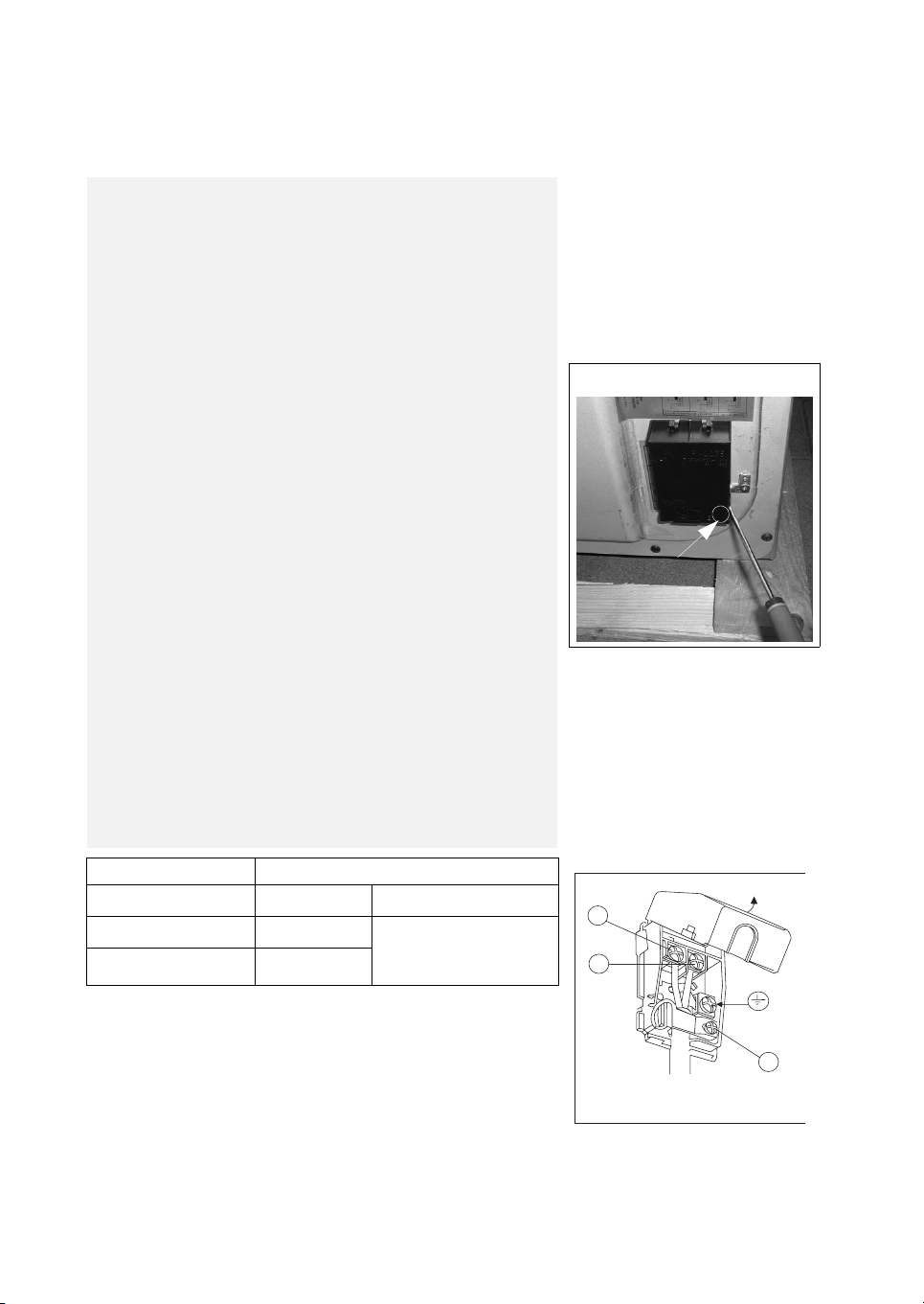
Connecting the mains cable
Open the mains terminal block cover as shown, unscrew the
cable clamp “A” and unscrew (not fully) the screws in the mains
terminal block which secure the three wires of the mains cable.
Fit the cable and refit the cable clamp “A” (fig. 1 ).
IMPORTANT
The wires in the mains lead are coloured in accordance with the
following code:
GREEN & YELLOW ............................................ EARTH
BLUE.................................................................... NEUTRAL
BROWN............................................................... LIVE
The supply cable must not come into contact with any
component the temperature of which exceeds the ambient
temperature by 50°C.
Easy access to the plug or the switch is ensured once the
appliance is installed.
Ensured that there is sufficient cable allowed for any subsequent
removal of the unit.
In order to avoid hazard, any electrical work performed on this
equipment or its associated wiring should only be done by persons
authorised by the manifacture or similary qualified persons.
Terminal block cover
A
Appliance type Single-phase alimentation 230 V~
All gas
All gas + elett. grill
All gas + hotplates
3 x 0,75 mm
3 x 1,5 mm
3 x 1,5 mm
2
2
2
Ty p e o f c ab le
Rubber H05 RR-F
or
Rubber H05 VV-F
L
N
A
Fig. 1
5
Page 3
This appliance is in Class 1.
The appliance must be used with the gas specified on the appliance data plate located on the
back cover (see details given on the product).
Installation and maintenance of the appliance must be carried out by a qualified technician in
compliance with the conditions established in the applicable regulation documents and the
ethical codes.
Gas connection
The gas supply system must comply with current local
regulations.
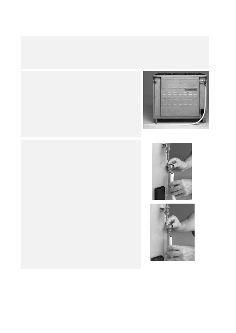
Important: the rubber hose must be installed in such a way
as not to be in contact with hot parts of the rear of the
appliance or kitchen. It must pass through an area free of
any hindrances and in a place where it can be inspected
along its entire length (Fig. 2).
When the appliance is connected to the gas supply, use
soapy water to check for gas leaks.
The rubber hose must be connected as shown in Fig. 3 and
4, in compliance with local applicable regulations
Natural gas
Use outlet connector GN for natural gas or a propane-air
mixture.
The rubber hose must be connected to the outlet connector and
secured using hose clamp A (Fig. 3).
Butane/Propane gas
Use outlet connector B/P for Butane/Propane gas.
The rubber hose must be connected to the outlet connector and
secured using hose clamp A (Fig. 4).
The maximum length of the rubber hose is 2 m. It must be a
standard hose and must be replaced within the date printed on it.
Important: Close the gas supply tap before carrying out any
maintenance operation.
Connection details: see the specific regulations for your country.
A
Fig. 2
Fig. 3
A
Fig. 4
6
Page 4

Gas adjustments
Use pressure regulators that are suitable for the gas
pressure values indicated in the Product Description Sheet
supplied separately.
If the appliance is arranged for a type of gas different from that
available, it is necessary to change the injectors, adjust the
minimum flame, change the outlet connector.
Carry out the following operations to change the hob injectors:
remove the grills; remove the burners, the burner caps
(see Fig. 5); change the injector and replace it with one suitable
for the new type of gas (see table in separate Product Sheet).
Replace the gas calibration label with the new label included in the
injector bag.
Refit everything in reverse order, making sure to correctly fit the
burner cap on the burner.
Minimum for hob taps
To adjust the minimum flame, proceed as follows:
• Light the burner and turn the knob to minimum ; remove
the tap knob (Fig. 6). Insert a small screwdriver next to the tap
pin (Fig. 7).
Attention: in taps with security valve, the minimum adjusting
screws is placed outside the rod tap (fig. 7A).
Turn the adjustment screw anticlockwise to increase the flame,
or clockwise to decrease it. Adjustment is correct when the flame
is approx. 3 - 4 mm.
The adjustment screw must be completely screwed down for
butane/propane gas.
Make sure the flame does not go out when switching suddenly
from high to low flame and vice versa.
Refit the knob.
Fig. 5
Fig. 6
Fig. 7
Fig. 7A
7
Page 5
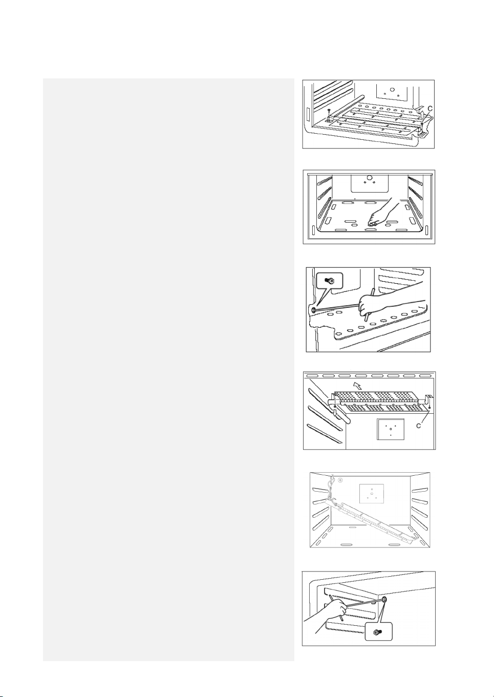
To change the oven injector, it is necessary to act as follows: open
the oven door, remove the lower side of the oven (see Fig. 8),
unscrew the screw C and disassemble the oven burner (see Fig. 9).
Change the injector (see Fig. 10) and replace it with another one
suitable for the new gas type (see table in separate Product Sheet).
Re - assemble everything in the opposite direction, paying
attention to place the burner in the right way on its rear slot.
To change the grill injector, it is necessary to act as follows:
open the oven door, unscrew the screw C (see Fig. 11) and
disassemble the grill burner (see Fig. 11A).
Change the injector (see Fig. 12) and replace it with another one
suitable for the new gas type (see table in separate Product
Sheet).
Fig. 8
Fig. 9
Fig. 10
Re-assemble everything in the opposite direction, paying
attention to place the burner in the right way on its rear slot.
8
Fig. 11
Fig. 11A
Fig. 12
Page 6

REGULATION OF AIR ADJUSTER (oven burner)
To do this,
unscrew the screw (A) in order to rotate the metal ring at the
end of the burner (Fig. 13).
In this way entrance of the air increases or decreases, obtaining a
correct flame.
Be sure that the flame does not lift or light back or present a
yellow coloration.
REGULATION OF AIR ADJUSTER (grill burner)
To do this,
unscrew the screw (A) in order to slip it forwards or backwards
(Fig. 14).
In this way entrance of the air increases or decreases obtaining a
correct flame.
Be sure that the flame does not lift or light back or present a
yellow coloration.
WARNING
On completion of all the burner gas type conversion operations,
re-do all the seals on the air supply controls.
Fig. 13
To raise the
cooking hob
end to push in
ahead
Fig. 14
Fig. 15
9
Page 7

Oven minimum flame adjustment
Light the oven burner at max. setting.
Close the door. Turn the knob to min. After approx. 20 minutes (at least to obtain first activation of the
thermostat), proceed as follows: remove the oven knob and insert a small screwdriver outside the
thermostat, as shown in the figure 7A.
Turn the adjustment screw clockwise to increase the flame and anticlockwise to decrease it. For correct
setting, make sure the flame height is 3/4 mm.
Room ventilation
Gas appliances
This appliance is not connected to a fume exhaust device.
Therefore it must be installed and connected in compliance with
current installation regulations.
Particular attention must be paid to the applicable standards
concerning room airing.
Room ventilation
This appliance can only be installed and used in well-ventilated
rooms, according to current regulations, with openings in the
walls or with special ducts enabling proper natural or forced
ventilation, thus ensuring permanent and adequate introduction
of air necessary for correct combustion and for extraction of
vitiated air.
In particular, if there is only this gas appliance in the room, a hood
must be installed above the appliance to ensure natural and direct
extraction of the vitiated air, with a straight vertical duct of length
equal to at least twice the diameter and a minimum section of at
least 100 cm
For the indispensable introduction of fresh air in the room, a
similar opening of at least 100 cm2 directly to the outside must be
provided at a height near floor level so as not to be obstructed on
the inside or outside of the wall and not to hinder the correct
combustion of the burners and the regular extraction of vitiated
air, and with a height difference of at least 180 cm with respect to
the outlet opening.
The quantity of air necessary for combustion must not be less
than 2 m
appliance rating plate).
In all other cases, when there are other appliances in the same
room, or when direct natural ventilation is not possible and
indirect natural ventilation of forced ventilation has to be created,
contact a qualified specialist for carrying out installation and
preparing the possible ventilation system in strict compliance with
current regulations.
Flues already used by other appliances must not be used for
exhausting combustion products.
2
.
3
/h for every kW of power (see total power in kW on the
10
Page 8

Installation
Important: The covering of the cabinets must be in heat
resistant (min. 90°C) material.
If the appliance is installed next to kitchen cabinets, ensure the
minimum clearances indicated in the following figure 16.
There are certain points to pay attention to when positioning the
cooker. Make sure to take into consideration the following
recommendations, in order to prevent any problems and
hazardous situations that may occur!
The cooker can be positioned near other cabinets provided their
height does not exceed the hob level.
In selecting a position for the cooker, make sure the appliance is
not placed next to a refrigerator and that there are no flammable
or combustible materials in the vicinity, such as curtains, etc.
which can quickly catch fire.
A minimum space of 20 mm between the metal rear cover of the
cooker and the wall is required to ensure air circulation.
If the counter tops are higher than hob level, they should be at
least 110 mm from the sides of the cooker.
To fit them, tilt the appliance and screw the 4 feet in the special
threads located in the corners (see Fig. 17).
Adjust leveling Legs
If range height adjustment is necessary, manually adjust the
leveling leg sleeves to loosen the 4 leveling legs. Leveling legs can
be loosened to add uo to a maximum of 5 cm.
This may be done with the range on its back or with the range
supported on 2 legs after the range has been placed back to a
standing position.
NOTE: To place range back up to a standing position, put a sheet
of cardboard or hardboard in front of the range. Using 2 or more
people, stand range back up onto the cardboard or hardboard.
min. 110 mm
min. 50 mm
min. 20 mm
min. 650 mm
min. 50 mm
min. 20 mm
min. 400 mm
Levelling leg
sleeves
Fig. 16
Fig. 17
11
Page 9

SERVICE INSTRUCTION
All service should be carried out by an authorised service
technician only.
WARNINGS
Before performing any repair or operation, switch the
appliance off.
The manufacturer declines all responsibility for any damage to
person, animals or things caused by failure to observe the rules
indicated above.
OVEN LIGHTS
Always ensure the oven unit is switched off at the mains before
replacing the oven light bulb.
To remove the light bulb, unscrew the glass cover anticlockwise
and remove.
Turn the bulb anticlockwise and remove.
Replace with the same type of bulb (Type E14 threaded clear
lamp 230/240 v. 16 watt T 300°C). Replace the lights carefully and
turn it clockwise.
USE AND MAINTENANCE
Be safe
Please read the rest of the instruction book which
contains important information to help you use the
appliance safely and efficiently.
USING GAS BURNERS
The following symbols are on the control panel
next to each knob:
Black circle gas off
Large flame maximum setting
Small flame minimum setting
The minimum position is at the end of the
anticlockwise rotation of the knob. All operation
positions must be chosen between the positions of
max. and min., never choose them between max.
and off.
AUTOMATIC ELECTRIC IGNITION
To turn on a burner, press the knob corresponding
to the selected burner and turn it anticlockwise to
the max. position. Keeping the knob pressed, the
electric automatic ignition of the burner will be
started up.
In case there is no electric current the burner can
also be lighted using a match.
ENERGY SAVING TIPS
The diameter of the pan bottom should be the
same as that of the burner. The burner flame must
never come out from the pans diameter.
• Use flat-bottomed pans only.
• Whenever possible, keep a lid on the pan while
cooking. You will not need as much heat.
• Cook vegetables, potatoes, etc. with as little
water as possible to reduce cooking times.
BURNERS PANS
Ø min. Ø max
RAPID 180 mm 220 mm
SEMI-RAPID 120 mm 200 mm
AUXILIARY 80 mm 160 mm
TRIPLE CROWN 220 mm 260 mm
12
Page 10

USING ELECTRIC HOTPLATES
(depending on the models)
When using an electric hotplate for the first time or after a long
period of disuse, turn the knob to 1 and let it heat for about 20
minutes to eliminate any possible moisture absorbed by the
internal insulating material.
- Dry the bottom of the pan before placing it on the hotplate.
- Turn the hotplate on only after placing the pan on it.
The hotplate is controlled by a commutator. Turn the knob to
position 1 in order to turn the hotplate on (Fig. 1). A warning light
on the control panel will inform you if the plate is on or off.
MANUAL IGNITION OF OVEN BURNER
(depending on the models)
To ignite the oven burner, simply insert a match through the
opening (Fig. 5) and then turn the tap to the maximum setting as
shown in figure 2.
After making sure that the burner has lit properly, gently close the
oven door. To obtain the temperature required, simply turn the
pointer of the knob to the chosen number or degrees (Tab. B)
Fig. 1
= CLOSED
Pos.1 : 140°C = MINIMUM
Pos.8 : 250°C = MAXIMUM
= GRILL
WARNING: Do not operate the ignition for more than 15
seconds. If the burner fails to ignite, leave the oven door
open for at least 1 minute before pressing the knob again.
Fig. 2
Fig. 5
13
Page 11

USE OF THE GAS GRILL
(depending on the models)
Manual ignition of the grill
Open the oven door, then turn the oven knob to
the right and place it on the grill position.
Bring a light match near the holes of the burner
placed on the oven upper part (Fig. 6).
Fig. 6
Automatic electric ignition of oven and grill
burner (depending on the models)
The oven door must always be completely
open, before the burner ignition
To ignite the burner press the knob and turn it
clockwise to the maximum position, for the oven
burner and anticlockwise to the grill position for the
grill burner. Keep it pressed to start up the
automatic ignition of the burner. In case there is no
electric current, the burner can also be lighted using
a match (Fig. 5 - 6).
It's necessary to keep on pressing the concerned
knob for 10 seconds after the ignition (Fig. 7).
In this way the safety valve will be started up.
If for any reason the burner flame goes out, repeat
the procedure as described above.
When you will be sure that the burner is on, close
softly the oven door.
To obtain the desired temperature, turn the knob
index to the selected number (Tab.B).
OVEN KNOB
POSITION
TAB. B
- 140°C
140
-
-
170
- 190°C
210
-
250
TEMPERATURE
140°C
150°C
160°C
170°C
210°C
230°C
250°C
Fig. 7
WARNING: Do not operate the ignition for
more than 15 seconds. If the burner fails to
ignite, leave the oven door open for at least 1
minute before pressing the knob again.
USE OF THE ELECTRIC GRILL
(depending on the models)
The electric grill can be operated turning the knob
clockwise on position (Fig. C).
A warning light on the control panel will light up to
inform you that the grill is on.
Second
level
SURFACE BAKING GRILL
(480x240)
grill
working light
Fig. C
The grill must be used with the door half-open (see
Fig. 8 A).
Fit the deflector S onto the centering pins N on the
top of the oven opening (Fig. 8 B).
Then gently close the oven door against the deflector.
14
Fig. 8 A
Fig. 8 B
Page 12

GRILL SURFACE
For optimum cooking results, use the surface indicated on the
grill, see figure 8 C.
USE OF THE TURNSPIT (according to the models)
TURNSPIT single
For utilization of the turnspit follow the instructions described.
- Put the food in spit L (see Fig. 9), paying attention to block it
within the two forks F and to balance it in order to avoid any
unnecessary effort in motor R.
- Put the spit on support G, after having put its opposite end
into hole P of motor R.
- Place the drip tray with a little water under the spit.
- Start up motor R and turn the grill on.
-Fit deflector S onto the centering pins N on the top of the
oven opening (see Fig. 8 A-B).
- When removing the spit wear oven mitts.
The turnspit can be operated turning the knob clockwise on
position , or press the marked button with the symbol .
BEFORE USING THE APPLIANCE
GRILL SURFACE
Fig. 8 C
Fig. 9
• Remove the accessories from the oven and heat
it at 200°C for about two hours to eliminate the
smell of protective grease and insulating
materials. Keep the window open during this
operation.
• Before use, remove:
- stickers located on the front of the appliance
and on the oven door, except the dataplate;
- cardboard protection and protective plastic
film on the control panel and other parts of
the appliance;
- any stickers on the accessories
(e.g. under the drip-tray).
1. Packing
The packing material is completely recyclable, and
is marked with the recycling symbol , which
identifies it as a type of material that must be sent
to local waste-disposal centres.
2. Product
This appliance is marked in compliance with
European Directive 2002/96/EC on Waste
Electrical and Electronic Equipment (WEEE).
By ensuring that this appliance is correctly
scrapped, the user can help prevent potentially
harmful consequences for the environment and the
health of people.
The symbol on the appliance or accompanying
documentation indicates that this product must not
be treated as household waste, but must be taken
to a collection centre for the recycling of electrical
and electronic appliances.
Disposal must be carried out in accordance with the
local environmental regulations on waste disposal.
For more detailed information about the
treatment, recovery and recycling of this product,
please contact your competent local authority, the
household waste collection service or the shop
where you purchased the appliance.
15
Page 13

PRECAUTIONS AND GENERAL ADVICE
• The appliance is designed solely for domestic
use for cooking food. No other use is allowed.
The Manufacturer declines all liability for
inappropriate use or incorrect setting of the
controls.
• Any repairs or adjustments must be carried out
exclusively by a qualified technician.
• Never expose the oven to atmospheric agents.
• Do not place heavy objects on the door as they
could damage the oven compartment and
hinges. Do not cling to the door.
• Do not hang anything heavy on the oven door
handle.
• Do not cover the oven floor with aluminium
foil or other objects.
• The oven door must close properly. The door
seals must be kept clean.
• Do not pour water directly inside a hot oven. The
enamel coating could become damaged.
• Fruit juice dripping from the baking tray may
leave permanent stains. It is advisable to clean
the appliance before reusing it.
• To prevent the oven coating from being
scratched, do not drag pots and pans across the
bottom of the oven.
• The accessible parts of the appliance may
become very hot during use. Keep children
away.
• Never use abrasive materials or substances to
clean the GLASS, as they could damage it.
• The unit becomes very hot during use. Do not
touch the heating elements in the oven.
• Residual condensation after cooking could
eventually damage the oven and surrounding
kitchen units. We recommend that you:
- set the lowest temperature;
- cover food;
- remove food from the oven;
- dry wet parts when the oven is cool.
• Caution: The front panel and oven door
handle become hot when the appliance is
used for a long time at high temperatures.
• Do not touch the appliance with wet parts of the
body or use it when barefoot.
• Do not pull the appliance or the power cable to
unplug it.
• Do not allow children to touch:
- the controls and the appliance in general,
especially during and immediately after use:
risk of injury;
- packing (bags, polystyrene, metal parts, etc.);
- any appliance to be scrapped.
• The appliance is not intended for use by children
or persons with limited physical, sensory or
mental abilities or without experience and
knowledge of it, unless they are under the
supervision of or instructed in its use by a person
responsible for their safety.
• Make sure the electrical cables of any other
appliances used near the oven do not touch hot
parts or get caught in the oven door.
• Do not place flammable materials in the oven or
nearby, due to the risk of fire if the oven is
inadvertently switched on.
• Use oven gloves to remove pans and accessories
when the oven is hot.
• If alcoholic beverages (e.g. rum, cognac, wine, etc.)
are added when roasting or baking cakes, etc.,
remember that alcohol evaporates at high
temperatures. Vapours released by the alcohol
may catch fire on coming into contact with the
electrical heating element.
• Do not heat or cook foods in closed containers.
The pressure created inside could cause them to
explode, damaging the oven.
• Do not use containers made of synthetic
material for cooking (except for packages
specifically designed for this purpose; see the
manufacturer's instructions). They could melt at
high temperatures.
• Always pay attention when cooking with oil and
grease. Oil and fat can overheat and catch fire!
• Never pull out fully loaded shelves. Use extreme
caution.
Do not use rough or abrasive materials or sharp
metal scrapers to clean the glass doors of the oven
since they may scratch the surface and cause the
glass to break.
Caution: glass lids may shatter when heated.
Turn off the burners before shutting the lid.
16
Page 14

OVEN ACCESSORIES
The accessories supplied depend on the model.
The accessories provided with the oven are listed in the
Product Description Sheet provided separately
(under Accessories).
Wire shelf (Fig. 1)
Th e wi re shel f ca n be used to gri ll f ood or as a s upp ort for baking
trays, cake tins and other cooking containers. It can be placed on
any of the runners in the oven.
Baking tray (Fig. 2)
For baking biscuits, cakes and pizzas.
This tray can also be used for collecting fat and any scraps of
food when placed under the grill; pour a little water in the driptray to prevent spatters of fat and smoke.
Knob guard (Fig. 3)
It protects the knobs against overheating during use of the grill.
Fig. 1
Fig. 2
Turnspit (Fig. 4)
Use the turnspit as indicated in the relevant chapter in the
Product Description Sheet.
Fig. 3
Fig. 4
17
Page 15

CLEANING AND MAINTENANCE
When cleaning the cooker, do not shift it beyond the
length of the tube.
Disconnect the appliance from the power supply before
carrying out any cleaning operation.
• Clean using a cloth moistened with warm soapy water or
diluted liquid detergent.
• Do not use abrasive, corrosive or chlorine products, or steel
wool.
• Do not use steam cleaners.
• Do not use flammable products.
• Do not leave acid or alkaline substances such as vinegar, salt,
lemon juice, etc., on the hob.
Stainless steel surface
• Clean with a specific commercial product.
Cleaning the burners
To clean the hob burners, lift them out of their seats (Fig. 1) and
place in a solution of hot water and non-abrasive detergent for
about 10 minutes. After cleaning and washing the burners,
thoroughly dry them.
Always make sure the openings are not blocked. It is
advisable to carry out this operation at least once a week or
whenever necessary. Make sure to properly refit the burners,
turning them slowly so that the burner caps engage in the injector
holder seat (if perfectly centred, the burner lowers a little and
locks in place).
Pan support maintenance
• Clean the pan supports with a sponge and detergent
whenever dirty.
• The pan supports will change colour near the burners. This is
perfectly normal and is due to the high temperature reached
during cooking.
Cleaning the electric hotplates
(depending on the model)
• The electric hotplates must be cleaned when they are lukewarm.
• Wipe them with a cloth moistened with water and salt, and
polish with a cloth moistened with oil.
Oven cleaning
• After cooking, wait for the oven to cool then clean it to
prevent the accumulation of cooking residuals.
• For stubborn grime, use a specific oven cleaning product,
following the instructions given on the package.
• Clean the outside of the oven with a sponge and lukewarm water.
• Do not use abrasive products or steel wool.
• Clean the door glass with a liquid detergent.
• Soak the accessories in water with washing up detergent
immediately after use. Food residues can be easily removed
using a brush or sponge.
Burner cap
Burner head
Burner base
Fig. 1
18
Page 16

Removing the oven door:
It should not be necessary to remove the oven door.
However, if removal is necessary, make sure the oven is off and
cool. Then, follow these instructions. The oven door is heavy.
To remove:
1. Open the door fully.
2. Position the hooks “A” of the hinges outwards (see fig. 1B).
3. Close the door slowly until reaching the hooks “A”, making
sure they lock in the slots “B” of the door, as shown in
figure 1C.
4. Using two hands, gently push the door inwards, allowing the
door hinges “C” to disengage the slots “D” (see fig. 1D), then
pull the door outwards until it comes off the oven.
After cleaning, refit the door correctly, carrying the removal
procedure in reverse order, and reposition to hooks “A” inwards
before closing the door (fig. 1E).
fig. 1B
fig. 1C
fig. 1D
fig. 1E
19
Page 17

TROUBLESHOOTING GUIDE
1. The appliance does not work:
• Check the mains power supply and that the
appliance is electrically connected.
• Switch the appliance off and on to see if the
problem persists.
AFTER-SALES SERVICE
Before calling the After-Sales Service
1. See if you can eliminate the problem on your
own (see “Troubleshooting Guide”).
2. Switch the appliance off and on again to see if the
problem persists.
If the fault persists after the above checks,
contact your nearest After-Sales Service.
Specify:
• the type of fault;
• exact type and model of oven;
• the After-Sales Service number (the number
given after the word “Service” on the dataplate)
located at the bottom right of frame of the oven
cavity and visible with the door open. The
service number is also given in the warranty
booklet;
• your full address;
• your telephone number.
IMPORTANT:
• Check that the oven selector is not turned to
“0” or to the “lamp” symbol .
For repairs, contact an Authorised After-Sales
Service, indicated in the warranty.
If any work is carried out by technicians not
belonging to the Manufacturer's authorised AfterSales Service centres, request a receipt specifying
the work performed and make sure the
replacement parts are original.
Failure to comply with these instructions can
compromise the safety and quality of the product.
20
 Loading...