

Whirlpool ACM927 WH, ACM 926/1 IX, ACM 881 WH, ACM 926 WH, ACM 871 WH INSTALLATION INSTRUCTIONS
...
INSTRUCTIONS FOR USE
INSTALLATION INSTRUCTIONS
BEFORE USING THE APPLIANCE
PRECAUTIONS AND GENERAL ADVICE
ENERGY SAVING TIPS
OVEN ACCESSORIES
CLEANING AND MAINTENANCE
TROUBLESHOOTING GUIDE
AFTER-SALES SERVICE
For best use of the oven, carefully read the operating instructions and keep them for future
consultation.
88
INSTALLATION INSTRUCTIONS
Electrical connection
Before connecting the appliance, make sure:
the mains voltage in your home matches that specified on the appliance dataplate;
1.
the electrical system adequate for appliance max. power absorption specified on the dataplate;
2.
the house electrical system is suitably earthed.
3.
• Connect the appliance to the power supply by means of a suitable disconnecting switch with
min. contact opening distance allowing complete disconnection in category III overvoltage
conditions, in compliance with the installation regulations.
After installation, the electrical components must only be accessible with the use of a special tool.
Notes:
The power cable must be H05VV-F type, in compliance with the table given below.
Type of appliance Single-phase power supply
230V
Gas-gas/mixed hob with
electric oven
Section 3 x 1 mm² when total electrical power ≤ 2300W
3 x 1.5 mm² when total electrical power > 2300W
Connect a power cable of suitable section:
Instructions for the installer
Warning
• Disconnect the appliance from the power supply before carrying out any repairs or
operation.
• Installation must be carried out by a qualified technician, in compliance with the current
safety regulations.
• The appliance must be earthed.
The Manufacturer declines any liability for injury or damage to people or property due to non-compliance
with the above-mentioned regulations. The appliance dataplate is located at the bottom right of frame of
the oven cavity and visible with the door open. Adjustment conditions are given on a label on the packing.
Do not use the oven door for handling operations, or for removing the appliance from the packing.
Cable H05VV
-F
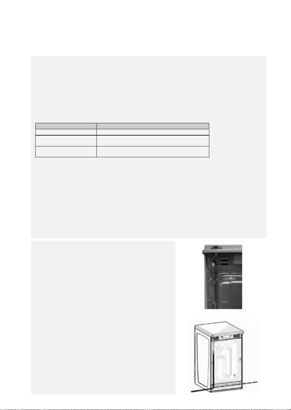
Gas connection
For information regarding gas connection instructions, see
the section on “standards” relevant to your country
(“References to National Regulations”).
The gas supply system must comply with current local
regulations.
The appliance must be connected to the gas supply or gas
bottle by means of a rigid copper or steel pipe with fittings
conforming to local regulations or by means of a continuous s/
steel hose conforming to local regulations.
The hose must not be longer than 2 m.
The hose must be connected directly to the elbow of the
outlet union (Fig.1).
Important: When using a hose, it must be installed so
that no part of it is contact with hot parts on the back of
the appliance or cooker. Its path must be free of any
hindrances and in a place where it can be inspected along
the entire length (Fig. 2).
When the appliance is connected to the gas supply, use soapy
water to check for gas leaks.
Fig. 1
Fig. 2
89
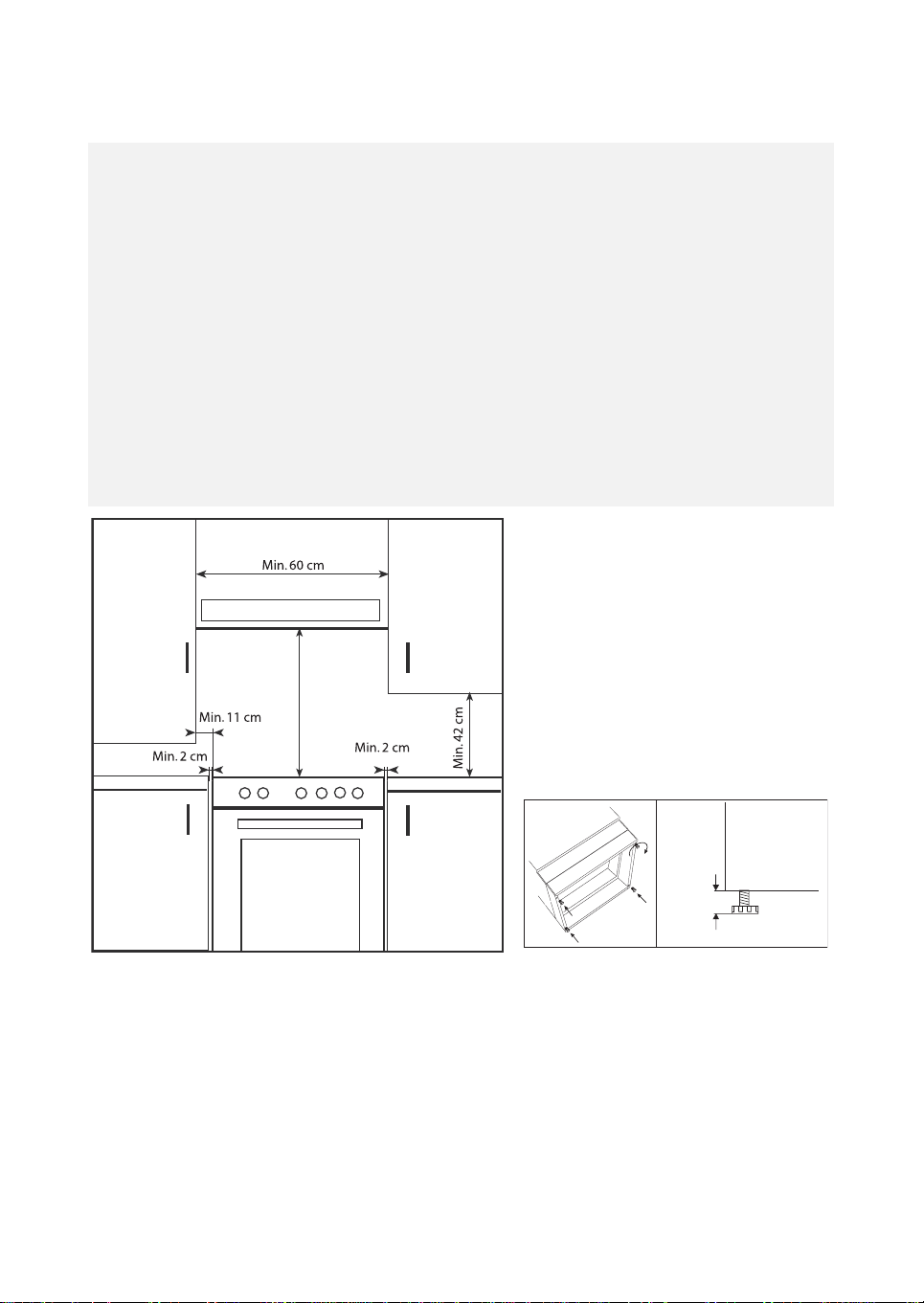
Installation
Important
: The covering of the cabinets must be in heat resistant (min. 90°C) material.
If the appliance is installed next to kitchen cabinets, ensure the minimum clearances indicated in the
following figure.
There are certain points to pay attention to when positioning the cooker. Make sure to take into
consideration the following recommendations, in order to prevent any problems and hazardous
situations that may occur!
The cooker can be positioned near other cabinets provided their height does not exceed the hob level.
In selecting a position for the cooker, make sure the appliance is not placed next to a refrigerator and
that there are no flammable or combustible materials in the vicinity, such as curtains, etc. which can
quickly catch fire.
A minimum space of 20 mm between the metal rear cover of the cooker and the wall is required to
ensure air circulation.
If the counter tops are higher than hob level, they should be at least 110 mm from the sides of the cooker.
To fit them, tilt the appliance and screw the 4 feet in the special threads located in the corners
(see Fig. 2).
Min. 50 cm (depending on the model)
Fig. 1
90
Min. 65 cm
Fig. 2
Max.
adjustment
15 mm

ELECTRICAL CONNECTION AND SAFETY
For the electrical connection, make sure to follow the
instructions given below:
The earth wire must be connected to the earth terminal ( ).
•
If there is no approved earthed electrical outlet in the place
where the appliance is to be installed, immediately contact to
our Authorised Service.
The earthed electrical outlet must be close to the appliance.
•
Do not use extension cords.
The power cable must not touch hot parts of the product.
•
If the power cable is damaged, contact a Qualified Service
•
Centre. The cable must be replaced by the Authorised
Service.
An incorrect electrical connection could damage your
•
appliance. Such damage is not covered by the warranty.
The appliance is arranged for a 230 Volt power supply. If the
•
power supply voltage is different, immediately contact to our
authorised service.
The power cable must not touch hot parts of appliance.
Otherwise it may become damaged.
This situation could cause short circuiting.
The manufacturer declines any liability for damage and loss due to
failure to comply with the following safety regulations
If replacing the power cable, the new one must have the same
characteristics that are specified in this manual.
To replace the cable, proceed as follows:
open the terminal board box;
•
undo the cable fixing screw A;
•
loosen the screw contacts and replace the cable with one of
•
the same length, complying with the table in the section
“Electrical connection”;
the
•
Yellow/Green
terminal and be approx. 20 mm longer than the line wires;
the
•
marked with the letter N;
the live wire must be connected to the terminal marked with
•
the letter L.
neutral wire must be connected to the terminal
Blue
earth wire must be connected to the
A
Electrical Connection Diagram
91
 Loading...