

AIR
CONDITIONER
? Ovens, Compactors, Room Air Conditioners, Dehumidifiers, Automatic Washers, Clothes Dryers, Freezers,
Refrigerator-Freezers,
Ice Makers,Dishwa!
Copy your Model and
Serial N urn bers here.. .
When you need service or call with a question, have
this information ready:
1.
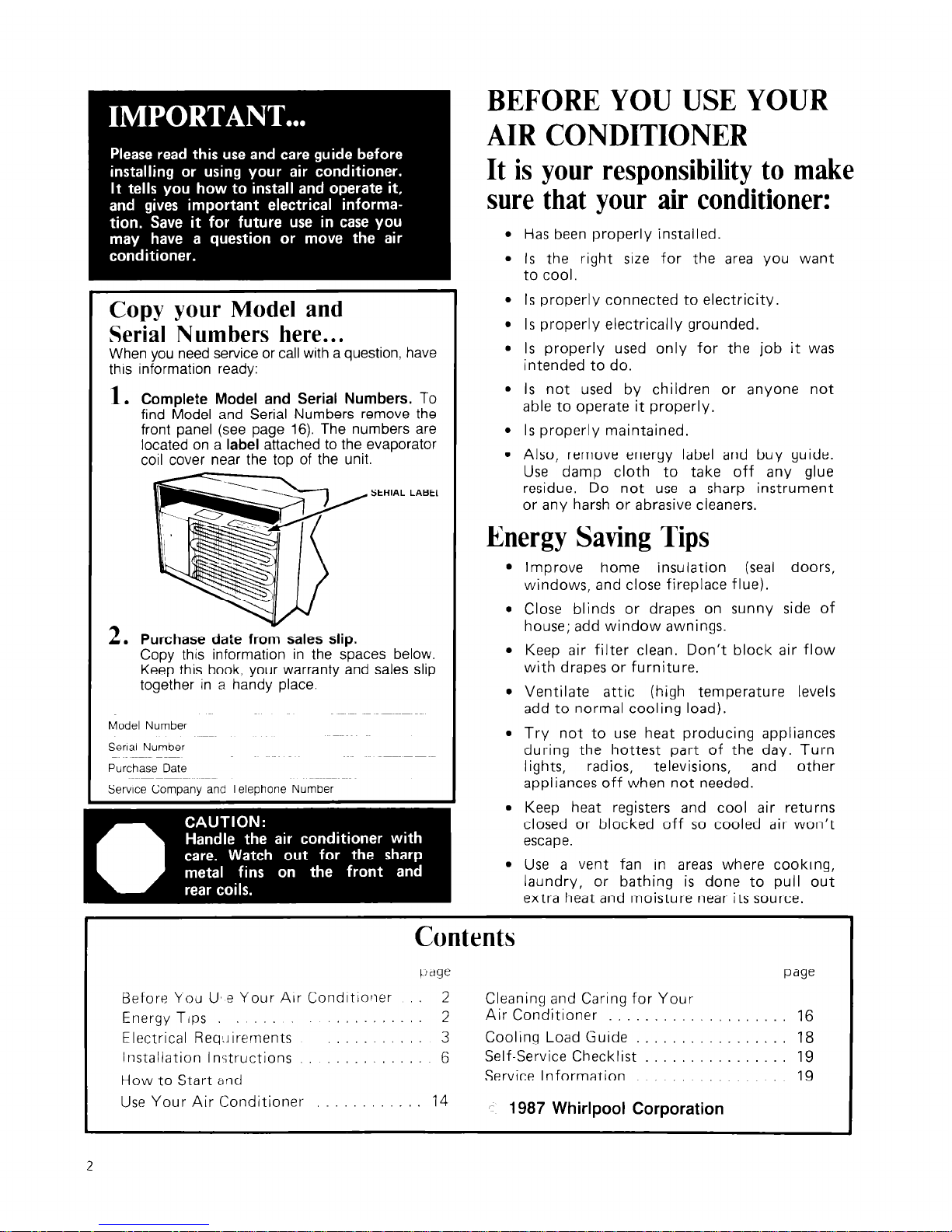
Complete Model and Serial Numbers.
To
find Model and Serial Numbers remove the
front panel (see page 16). The numbers are
located on a
label
attached to the evaporator
coil cover near the top of the unit.
SERIAL LAB.3
A
2. Purchase date from sales slip.
Copy this information in the spaces below.
Keep this book, your warranty and sales slip
together in a handy place.
Model Number
Senal Number
Purchase Date
Service Company and Telephone Number
BEFORE YOU USE YOUR
AIR CONDITIONER
It is your responsibility to make
sure that your air conditioner:
l
Has been properly installed.
l
Is the right size for the area you want
to cool.
l
Is properly connected to electricity.
l
Is properly electrically grounded.
l
Is properly used only for the job it was
intended to do.
l
Is not used by children or anyone not
able to operate it properly.
l
Is properly maintained.
l
Also, remove energy label and buy guide.
Use damp cloth to take off any glue
residue. Do not use a sharp instrument
or any harsh or abrasive cleaners.
Energy Saving Tips
l
Improve home insulation (seal doors,
windows, and close fireplace flue).
l
Close blinds or drapes on sunny side of
house; add window awnings.
l
Keep air filter clean. Don’t block air flow
with drapes or furniture.
l
Ventilate attic (high temperature levels
add to normal cooling load).
l
Try not to use heat producing appliances
during the hottest part of the day. Turn
lights,
radios, televisions,
and
other
appliances off when not needed.
l
Keep heat registers and cool air returns
closed or blocked off so cooled air won’t
escape.
l
Use a vent fan in areas where cooking,
laundry, or bathing is done to pull out
extra heat and moisture near its source.
F3efore You U, e Your Air Conditioner
Energy Tips
Electrical ReqLlirernents
Installation InGructions
How to Start and
I
Use Your Air Conditioner
Contents
tjage
page
2
Cleaning and Caring for Your
2
Air Conditioner . . 16
3
Cooling Load Guide 18
6
Self-Service Checklist 19
Service Information 19
14
‘- 1987 Whirlpool Corporation
2
Electrical Requirements
For Your Air Conditioner
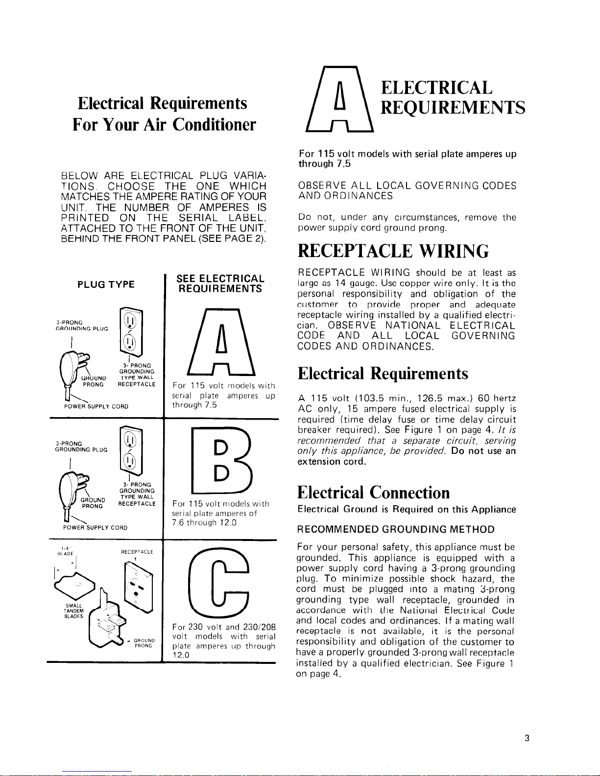
BELOW ARE EL.ECTRICAL PLUG VARIAT-IONS. CHOOSE THE ONE WHICH
MATCHES THE AMPERE RATING OF YOUR
UNIT. THE NUMBER OF AMPERES IS
PRINTED ON THE SERIAL LABEL,
ATTACHED TO THE FRONT OF THE UNIT,
BEHIND THE FRONT PANEL (SEE PAGE 2).
PLUG TYPE
3-PRONG
GROUNDING PLUG
I
POWER SUPPLY
J-PRONG
GROUNDING PLUG
POWER SUPPLY
3- PRONG
GROUNDING
TYPE WALL
RECEPTACLE
CORD
SEE ELECTRICAL
REQUIREMENTS
A
n
For 115 volt models with
serial plate amperes up
through 7.5
D
B
D
For 115 volt models with
serial plate amperes of
7.6 through 12.0
For 230 volt and 2301208
volt models with serial
plate amperes up through
12.0
ELECTRICAL
REQUIREMENTS
For 115 volt models with serial plate amperes up
through 7.5
OBSERVE ALL LOCAL GOVERNING CODES
AND ORDINANCES
Do not, under any circumstances, remove the
power supply cord ground prong.
RECEPTACLE WIRING
RECEPTACLE WIRING should be at least as
large as 14 gauge. Use copper wire only. It is the
personal responsibility and obligation of the
customer to provide proper and adequate
receptacle wiring installed by a qualified electrician. OBSERVE NATIONAL ELECTRICAL
CODE AND ALL LOCAL GOVERNING
CODES AND ORDINANCES.
Electrical Requirements
A 115 volt (103.5 min., 126.5 max.) 60 hertz
AC only, 15 ampere fused electrical supply is
required (time delay fuse or time delay circuit
breaker required). See Figure 1 on page 4.
It
is
recommended that a separate circuit, serving
only this appliance, be provided.
Do not use an
extension cord.
Electrical Connection
Electrical Ground is Required on this Appliance
RECOMMENDED GROUNDING METHOD
For your personal safety, this appliance must be
grounded. This appliance is equipped with a
power supply cord having a 3-prong grounding
plug. To minimize possible shock hazard, the
cord must be plugged into a mating 3-prong
grounding type wall receptacle, grounded in
accordance with the National Electrical Code
and local codes and ordinances. If a mating wall
receptacle is not available, it is the personal
responsibility and obligation of the customer to
have a properly grounded 3-prong wall receptacle
installed by a qualified electrician. See Figure 1
on page 4.

Figure 1
TACLE
POWER-SUPPLY CORD
ALTERNATE GYOUNDING METHOD
f changing ano proper!y grounding the wall
receptacle is imrjossible and where local codes
permit
iconsult your electrrcal inspector), a
remporary adapter may be plugged into the
existing 2-prong wall receptacle to mate with the
3-prong power s~:pply cord. See Figure 2. THIS,
HOWEVER. IS ~JOT RECOMMENDED.
of tnis is done, y )u rnusr connect the grounded
eyelet on the adapter to the wall receptacle
cover plate screw and from this same screw, you
tnust connect a separate copper ground wire
I -14 minimum) IO a grounded cold water pipe. r
See Figure 2. Do not ground to a gas supply
pipe. Do not connect to electrical supply until
(appliance is permanently grounded.
ELECTRICALLY
GROUNDED MET
COLD WATER PIP
(REMOVE PAINT, e
GROUND ASSEMBLY
(ATTACH TO GROUNDED
METAL COLD
WATER PIPE)
PLATE
WALL
RECEPTACLE
POWER SUPPLY CORD
‘Cold water pipr rnust have metal continuity to
electrical grounrl and not be interrupted by
plastic, rubber c)r other electrically insulating
<onnectors (incleilding water meter or pump)
without adding a jumper wire at these con
iel:tions.
ELECTRICAL
REQUIREMENTS
For 115 volt models with serial plate amperes of
7.6 through 12.0
OBSERVE ALL LOCAL GOVERNING CODES
AXD ORDlhANCES
Do not, under any circumstances, remove the
power supply cord ground prong.
RECEPTACLE WIRING
RESEPTACLE WIRING should be at least as
large as 14 gauge. Use copper wire only. It is the
personal responsibility and obligation of the
customer to provide proper and adequate
receptacle wiring installed by a qualified electrician. OBSERVE NATIONAL ELECTRICAL
CODE AND ALL LOCAL GOVERNING
CODES AND ORDINANCES.
Electrical Requirements
A 115 volt (103.5 min., 126.5 max.) 60 hertz
AC only, 15 ampere fused electrical supply is
required (time delay fuse or time delay circuit
breaker required). See Figure 3. lt is required
that a separate circuit, serving only this appliance,
be provided.
Do not use an extension cord.
Electrical Connection
Electrical Ground is Required on this Appliance
RECOMMENDED GROUNDING METHOD
For your personal safety, this appliance must be
grounded. This appliance is equipped with a
power supply cord having a 3-prong grounding
plug. To minimize possible shock hazard, the
cord must be plugged into a mating 3-prong
grounding type wall receptacle, grounded in
accordance with the National Electrical Code
and local codes and ordinances. If a mating wall
receptacle is not available, it is the personal
responsibility and obligation of the customer to
have a properlv grounded 3-pronq wall receptacle
installeb by a qualified
Figure 3
3.PRONG
GROUNDING PLUG
.
electrician. See Fig.ure 3.
GROUNDING
TYPE WALL RECEPl
POWER SUPPLY CORD
-ACLE
ALTERNATE GROUNDING METHOD
If changing and properly grounding the wall
receptacle is impossible and where local codes
permit (consult your electrical inspector), a
temporary adapter may be plugged into the
existing 2-prong wall receptacle to mate with the
3-prong power supply cord. See Figure 4. THIS,
HOWEVER, IS NOT RECOMMENDED.
If this is done, you must connect the grounded
eyelet on the adapter to the wall receptacle
cover plate screw and from this same screw, you
must connect a separate copper ground wire
(#14 minimum) to a grounded cold water pipe.*
See Figure 4. Do not ground to a gas supply
pipe. Do not connect to electrical supply until
appliance is permanently grounded.
Figure 4
ELECTRICALLY
GROUNDED META
COLD WATER PIP
(REMOVE PAINT,
SCRE
J-PRONG
GROUNDI
PLUG
RECEPTACLE
ROUND PRONG
POWER SUPPLY CORD
*Cold water pipe must have metal continuity to
electrical ground and not be interrupted by
plastic, rubber or other electrically insulating
connectors (including water meter or pump)
without adding a jumper wire at these con-
nections.
cc
ELECTRICAL
REQUIREMENTS
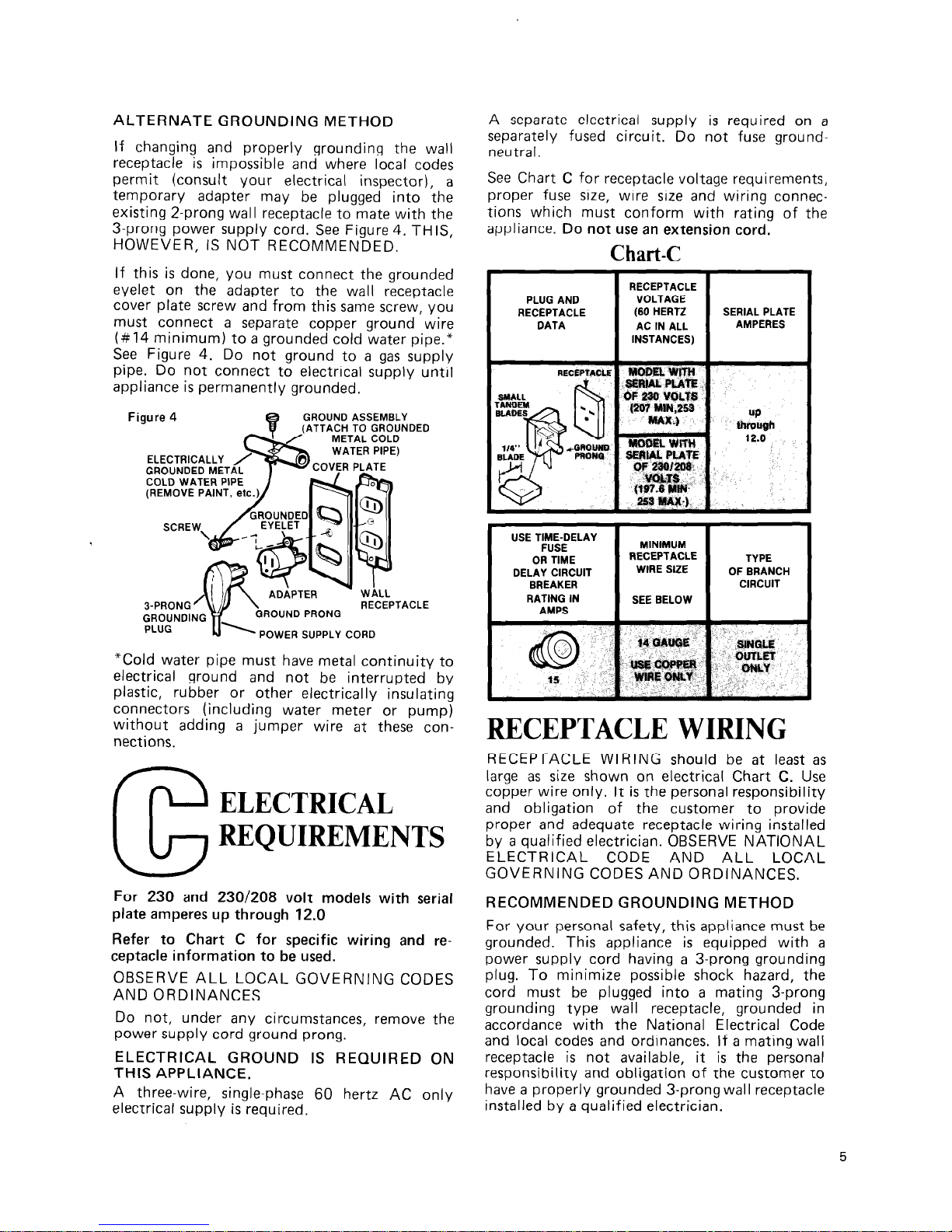
For 230 and 230/208 volt models with serial
plate amperes up through 12.0
Refer to Chart C for specific wiring and re-
ceptacle information to be used.
OBSERVE ALL LOCAL GOVERNING CODES
AND ORDINANCES
Do not, under any circumstances, remove the
power supply cord ground prong.
ELECTRICAL GROUND IS REQUIRED ON
THIS APPLIANCE.
A three-wire, single-phase 60 hertz AC only
electrical supply is required.
A separate electrical supply is required on a
separately fused circuit. Do not fuse ground-
neutral.
See Chart C for receptacle voltage requirements,
proper fuse size, wire size and wiring connections which must conform with rating of the
appliance.
Do not use an extension cord.
Chart-C
PLUG AND
I
RATING IN
I
SEE BELOW
AMPS
I
I
RECEPTACLE WIRING
RECEPTACLE WIRING should be at least as
large as size shown on electrical Chart C. Use
copper wire only. It is the personal responsibility
and obligation of the customer to provide
proper and adequate receptacle wiring installed
by a qualified electrician. OBSERVE NATIONAL
ELECTRICAL CODE AND ALL LOCAL
GOVERNING CODES AND ORDINANCES.
RECOMMENDED GROUNDING METHOD
For your personal safety, this appliance must be
grounded. This appliance is equipped with a
power supply cord having a 3-prong grounding
plug. To minimize possible shock hazard, the
cord must be plugged into a mating 3-prong
grounding type wall receptacle, grounded in
accordance with the National Electrical Code
and local codes and ordinances. If a mating wall
receptacle is not available, it is the personal
responsibility and obligation of the customer to
have a properly grounded 3-prong wall receptacle
installed by a qualified electrician.
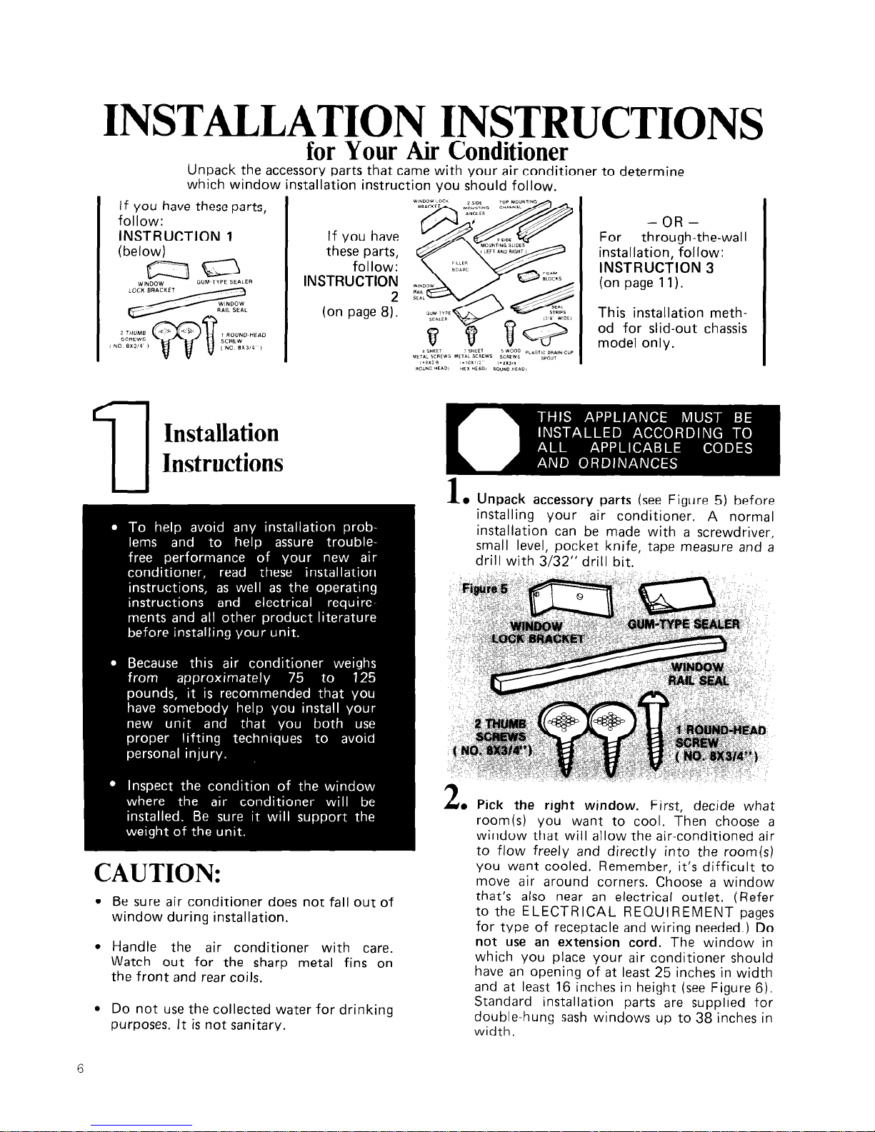
INSTALLATION INSTRUCTIONS
for Your Air Conditioner
Unpack the accessory parts that came with your air conditioner to determine
which window installation instruction you should follow.
If you have these parts,
follow:
INSTRUCTION 1
(below)
atg=l
WINDOW
GUM TlPE SEI\IER
u
Installation
Instructions
If you have
these parts,
follow:
INSTRUCTION
2
(on page 8).
CAUTION:
l
Be sure air conditioner does not fall out of
window during installation.
l
Handle the air conditioner with care.
Watch out for the sharp metal fins on
the front and rear coils.
l
Do not use the collected water for drinking
purposes. It is not sanitary.
-OR-
For
through-the-wal I
installation, follow:
INSTRUCTION 3
(on page 11).
This installation method for slid-out chassis
model only.
1
l Unpack accessory parts
(see Figure 5) before
installing your air conditioner. A normal
installation can be made with a screwdriver,
small level, pocket knife, tape measure and a
drill with 3/32” drill
bit.
Am Pick the right window.
First, decide what
room(s) you want to cool. Then choose a
window that will allow the air-conditioned air
to flow freely and directly into the room(s)
you want cooled. Remember, it’s difficult to
move air around corners. Choose a window
that’s also near an electrical outlet. (Refer
to the ELECTRICAL REQUIREMENT pages
for type of receptacle and wiring needed.)
Do
not use an extension cord.
The window in
which you place your air conditioner should
have an opening of at least 25 inches in width
and at least 16 inches in height (see Figure 6).
Standard installation parts are supplied for
double-hung sash windows up to 38 inches in
width.

3
. Remove front panel
by pushing top down and
pulling toward you (see Figure 7). This
protects the plastic front from damage and
makes the air conditioner easier to handle
4
l
Center air conditioner in window.
Rear of
unit must be’ raised slightly to position lower
rail of air conditioner behind and up against
back side of window sill ( see Figure 8).
CAUTION: BE SURE UNIT DOES NOT
FALL OUT OF WINDOW.) Lower the
window sash firmly behind the top mounting
channel.
3
l
Leveling air conditioner
is not required in a
normal installation. The proper slope is
designed into the product. However, be sure
you have approximately a one-half bubble
(X”) downward tilt to the outside for proper
water drainage (see Figure 9). If necessary,
reposition or shim cabinet to provide the
proper tilt or side-to-side leveling
Figure IQ
6
. Pull out sliding curtains
while holding air
conditioner in window. Extend curtains on
both sides until they engage window channels.
Pulling slightly inward allows curtains to slide
easily. Mark and make 3/32” pilot holes
before installing thumb screws in side handles
of curtains (see Figure 10. Or, if space is a
problem, use holes in top flanges of curtains.
(CAUTION: BE SURE UNIT DOES NOT
FALL OUT OF WINDOW.)
Figure 11
.,
WtIfdimW
LOCK
w1NDow fS@GKET
RAIL SEA&
7

7
0
8
l
Install window rail seal and window lock
bracket.
Press foam window rail seal into place
and cut to proper length (see Figure 11). Mark and
make a 3j&” pilot hole, then install lock bracket
using roundhead screw. (CAUTION: KEEP WINDOW LOCK BRACKET INSTALLED AT ALL
TIMES TO BE SURE UNIT DOES NOT FALL
OUT OF WINDOW. REMOVE ONLY WHEN YOU
WISH TO REMOVE AIR CONDITIONER FROM
WINDOW.) Seal small openings around installation with gum-type sealer.
Attach front panel by placing bottom edge on
clips and pushing top down, then in and up.
Installation
Instructions
CAUTION:
l
Be sure air conditioner does not fall out of
window during installation.
l
Handle the air conditioner with care. Watch
out for the sharp metal fins on the front
and rear coils.
1
l
Unpack accessory
parts
(see Figure12) be-
fore installing your
air conditioner. A normal
installation can be
made with a screwdriver,
saw, small level, pocket knife, tape measure
and drill with 3/32” drill bit.
Figure 12
4 SHEET
7 S-HEET
5 WooD PLASTIC DRAIN-CUP
METAL SCREWS METAL SCREWS SCREWS
SPOUT
(S.3XWe.”
(aloX1/2”
(#8X3/4”
ROUND HEAD)
HEX HEAD) ROUND HEAD)
2
l
Pick the right window.
First, decide what
room(s) you want to cool. Then choose a
window that will allow the air-conditioned air
to flow freely and directly into the room(s)
you want cooled. Remember, it’s difficult to
move air around corners. Choose a window
that’s also near an electrical outlet. (Refer to
ELECTRICAL REQUIREMENTS for receptacle and wiring needed.)
Do not use an
extension cord.
The window in which you
place your air conditioner should have an
opening of at least 26 inches in width and at
least 18 inches in height (see Figure 13 ).
Standard installation parts are supplied for
double-hung windows up to 40 inches in
width.
l
Do not use the collected water for drinking
purposes. It is not sanitary.
8

Figure 13
.
c
4
3
l
Remove front panel
by pushing top down
and pulling toward you (see Figure 14). This
protects the panel from damage and makes
the air conditioner easier to handle during
installation.
Figure 14
GROUND WIRE SCREW
“HANDLE
4
. Slide unit out
of
cabinet.
First, disconnect the
green ground wire at the left-front corner of
base of unit by Iremoving retaining screw (save
screw for reuse later). Now slide unit out of
cabinet by pulling out on handle on bottom
5
(see Figure 15).
o Attach seal stri;)s to cabinet. Place 3/8” wide
self-adhering st & strip or window side of
bottom flange. Now, starting at the lower
corner of the cabinet, apply seal strips over
the center line of the pre-drilled holes for one
of the side mounting angles, over the center
line of pre-drilled holes for the top mounting
channel, and over the center line of pre-drilled
holes for the other side mounting angle. (See
Figure 16.)
Figure
16
\
b
6
a
Attach side mounting
angles to the sides of
the cabinet by using four hex-head sheet
metal screws. (See Figure 17 .) Insert bottom
screws first. Be sure flange of each side
mounting angle faces inside. Now attach top
mounting angle to cabinet by using three hexhead sheet metal screws, Again, be sur
flange is facing inside.
Figure
18
MEASURE DISTANCE FROM INSIDE
e tallest

7
l
Measure and cut filler board
to proper sizes.
First, measure the distance from inside one
window channel to the inside of the other
channel and subtract X”. (See Figure 18 .)
Now subtract the width of the air conditioner
and divide by 2. This will give you the width
to cut each filler board. Be sure to cut the
filler ooard down the mid-section of its
iongest
measurement. Because the filler
boards will be equal in width, they will
automatically center your air conditioner
in your window.
,Back
Fiaure
19
Ad
I
LEFT
FILLER
I
BOARD
LA<
Front
8
l
Apply seal strips and attach filler boards. De-
termine which will be your left and right filler
boards. The holes on each board should align
with the holes in the side mounting angles.
Each filler board should also extend about %”
above the top edge of the air conditioner
cabinet. Now apply 3/8”-wide seal strips on
the room side of each filler board as shown
in Figure 19 (i.e. along the bottorn edge and
window channel edge). Also place a seal strip
along the top outside edge of each filler board.
Now attach the filler boards to the side
mounting angles with four, 3/8”, round
headed sheet metai screws. Tighten the screws
only loosely,
so the filler boards can be
moved back and forth.
9
. Insert side mounting slides
all the way into
top mounting channel.
10
*Place
cabinet in window
by turning cabinet to
one side to get one filler board into window
channel. Now maneuver other filler board
into other window channel (see Figure 20 ).
Reaching through window opening, push
filler boards from outside as far toward you
as they will go, Extend the mounting slides
outward into the window channels on both
sides. Pull the cabinet toward you to position
the side mounting slides as far forward in the
window channels as possible. Now mark and
make a 3/32” pilot hole for each wood screw
used to secure the slides in the window
channels (see Figure 21). Be sure to use the
foam blocks that are provided (see Figure
20).
CAUTION: BE SURE CABINET DOES NOT
FALL OUT OF WINDOW.

11
l
Lower window and level air conditioner.
Lower the window firmly behind the top
mounting channel. Leveling the cabinet is not
required in a normal installation since the
proper slope is designed into the product.
However, be sure you have approximately a
one-half bubble (5/8”) downward tilt to the
outside for proper water drainage. If necessary,
reposition or shim cabinet to provide the
proper tilt or side-to-side leveling. Now
tighten all four filler-board screws. Finally,
make two 3/32” pilot holes into the window
sill, using the holes in the cabinet as a guide.
Use two wood screws to secure the bottom of
the cabinet to the window sill. (See Figure
12
. Install window seal and window lock bracket.
Press foam window seal into place and cut to
proper length (see Figure 23 ). Install lock
bracket using wood screws. Make a 3/32”
pilot hole first. (CAUTION: WINDOW LOCK
BRACKET
MUST
BE INSTALLED AT ALL
TIMES TO BE SURE AIR CONDITIONER
DOES NOT FALL OUT OF WINDOW.
REMOVE BRACKET ONLY WHEN YOU
WISH TO REMOVE AIR CONDITIONER
FROM WINDOW.)
Seal small openings around installation with
gum-type sealer.
installed where this is undesirable, you can
direct the water to a more suitable spot by
simply attaching a 5/8”-inside-diameter, thinwalled hose to the drain spout at rear of
cabinet.
l
Insert air conditioner into cabinet.
Do not
push against sharp fins and plastic parts.
Attach green ground wire to the left-front
corner of unit base by using retaining screw
(see Figure 24).
(CAUTION: KEEP WIRE CONNECTED
WHENEVER AIR CONDITIONER IS IN
CABINET. IT IS THERE FOR YOUR
ELECTRICAL SAFETY DURING OPERATION
AND MAINTENANCE.)
13
l
Attach front by
placing bottom edge on clips
and pushing top down, then in and up.
Through-the-wall
Installation Instructions
.
for slide-out chassis model only
13
. Install plastic drain-cup spout
into hole at rear
of cabinet. Spout should be facing downward
through hole.
OPTIONAL: During high
humidity, condensate may drip from the
outside of your air conditioner onto the
ground below. If your air conditioner is
11

CAUTION:
Be sure air conditioner does not fall during
installation.
Handle the air conditioner with care.
Watch out for the sharp metal fins on
the front and rear coils.
Do not use the collected water for drinking
purposes. It is not sanitary.
Pick the right wall.
First, decide what room(s)
you want to cool, Then choose a wall that
will allow the air-conditioned air to flow
freely and directly into the room(s) you want
cooled. Remember, it’s difficult to move air
around corners. Choose a location that’s
also near an electrical outlet. (Refer to
ELECTRICAL REQUIREMENTS for re-
ceptacle and wiring needed.) Do
not use an
extension cord. (CAUTION: DO NOT LOCATE
AIR CONDITIONER WHERE PLASTIC
CABINET FRONT WILL BE EXPOSED TO
A HEAT SOURCE THAT RAISES THE
SURFACE TEMPERATURE IN EXCESS
OF 120” F.)
Choose the type of decorative molding you
want to use around the room side of the cabinet. Your choice affects the finish frame
alignment with the inside wall. When using a
wood, metal or plastic molding, the finish
frame should almost line up with the inside
wall. If the wall is plastered to the cabinet
and no molding is used, the finish frame
must be set into the wall by l/2” (see Figure
25 for frame construction or Figure 26 for
brick veneer construction). Cut through two
studs for support.
3
. Provide an opening through the wall
for a
finish frame. Observe all local governing codes
and ordinances. For wall opening dimensions,
use those shown in Figure 27 and add wood
frame thickness (use 1” lumber or heavier).
When determining finish frame thickness,
be sure you do not cover side cabinet louvers.
A 4” minimum clearance between side cabinet
louvers and adjoining wall allows for proper
airflow into air conditioner.
4
l
Construct finish frame.
Apply creosote or
something equal to the outside exposed
surface.
5
l
Install the finish frame
in the wall opening.
Square and level frame and nail it securely to
the studs.

6
l
The front,
escutcheon plate and knobs are
packaged separately. This protects the plastic
front from damage and makes the air conditioner easier to handle during installation.
7
l
Slide unit out of cabinet.
First, disconnect the
green ground wire at the left-front corner of
base of unit by removing retaining screw (save
screw for reuse later). Now slide unit out of
cabinet by pulling on handle at bottom (see
page 9, Figure 15).
8
l
Insert exterior cabinet through wall opening.
Leave %”
minimum overhang into the room
at top of cabinet, after allowing for trim. For
proper outward water drainage, shim or
reposition cabinet to provide the proper
downward tilt to the outside (% bubble or I”)
and side-to-side leveling.
9
e Fill all spaces
between cabinet and finish
frame with insulation.
10
l
Drill holes
in the cabinet and attach it securely
to finish frame. Use ten #lO x 1” wood
screws (four screws for each side and two
screws for the top; not included). Do not
overtighten screws or cabinet will distort and
provide a poor air seal between cabinet and
unit.
11
l
Insert air condttioner into cabinet. Do not
push against sharp fins and plastic parts.
Attach
green ground wire to the left-front corner of
unit base by using retainer screw. (CAUTION:
KEEP WIRE CONNECTED WHENEVER
AIR CONDITIONER IS IN CABINET. IT IS
THERE FOR YOUR ELECTRICAL SAFETY
DURING OPERATING AND MAINTENANCE.)
13
l
Attach front panel, place bottom edge on
clips and push down, then in and up.
14
l
Caulk
all outside wall openings around cabinet.
Fig
13
. If needed,
install molding around room side of
cabinet. OPTIONAL: During high humidity,
condensate may drip from the outside of your
air conditioner onto the ground below. If
your air conditioner is installed where this is
undesirable, you can direct the water to a
more suitable spot by simply attaching a
5/8-inch inside-diameter, thin-walled hose to
the drain spout at rear of cabinet (see
Figure 29 ).
12
l
Place escutcheon plate into position.
Insert
knobs through holes and press them onto
shafts (see Figure 28).
13

2
. To circulate room air
Set exhaust control to CLOSED. Adjust fan
control to FAN ONLY.
CLOSED
FAN ONLY
#1
2
. To bring in outside air
Set exhaust control to FRESH AIR. Adjust
fan control to FAN ONLY.
FRESH AIR
FAN ONLY
#l
For Exhaust Controls With
3
. To circulate room air
EXHAUST and FRESH AIR
Settings
Set exhaust control to OFF. Adjust
control to FAN ONLY.
1
l
To exhaust room air
Set exhaust control to EXHAUST. Adjust fan
control to speed desired. Set thermostat on
#l, if no cooling is desired.
EXHAUST
OFF
FAN ONLY
15

2
. ‘1’0 circulate room air
Set exhaust control to CLOSED. Adjust fan
control to FAN ONLY.
CLOSED
FAN ONLY
For Exhaust Controls With
EXHAUST and FRESH AIR
Settings
1
l
To exhaust room air
Set exhaust control to EXHAUST. Adjust fan
control to speed desired. Set thermostat on
#l, if no cooling is desired.
EXHAUST
LO COOL
#l
2
l
To bring in outside air
Set exhaust control to FRESH AIR. Adjust
fan control to FAN ONLY.
Set exhaust control to OFF. Adjust fan
control to FAN ONLY.
OFF
FAN ONLY
15

Changing Air Direction
l-he louvers in the grille area at the top of the air
conditioner control the direction of the cooled air.
2
l
‘J/hen the front moves away from top of
cabinet, pull top of front toward you.
3
l
Lift up and away from the bottom spring
clips.
Figure 30
1
l
2
l
3
0
4
l
Move the tai)s at the top or bottom of the
grille to the right, left or straight ahead.
Simply move the tabs in the direction you
want the air to go. (See Figure 30 .)
On most models, the louvers can only be
adjusted left or right. The front set is fixed
and directed upward.
On some models, air flow can be directed up
or down. Move the tab in the center louver to
direct air.
On some models, all louvers are fixed. The
louvers can not be adjusted.
Cleaning and Caring For Your
Air Conditioner
‘roper use and care of your air conditioner will
lelp insure longer life and lower operating costs.
Fol!ow these instructions carefully. Call your
dealer for an annual checkup,
Cleaning of Front Panel
1
. Remove the front panel from unit when
cleaning. Press down at top edge of the
front as shown in Figure 31.
4
l
5 a
Clean front panel with warm water and mild
soap or detergent. Use a soft cloth. Rinse and
dry. The filter should be cleaned at this time.
Replace front panel.
Wipe control panel clean with a soft dry cloth.
Cleaning Air Conditioner Filter
The filter is cleanable. A clean filter helps
remove dust, lint and other particles from the
air. Check every two weeks to see if filter
needs cleaning.
Figure 32

1
l
2
l
3
l
Remove filter from plastic front frame, by
removing elastic band which holds it in
place (see Figure 32).
Clean filter, using a vacuum cleaner.
-OR-
If very dirty, wash filter with warm water
and mild detergent. Air dry thoroughly
before replacing.
Annual Maintenance for Your
Air Conditioner
Your air conditioner needs annual maintenance to
help insure steady, top performance throughout
tie year.
Call the service company recommended by your
dealer to:
l
Inspect and clean the coils and condensate
water passages.
. Check fan and oil the fan motor.
l
The compressor is sealed and needs no oiling.
Expense of annual inspection is customer’s
responsibility,
- or -
If you are famliiar with electrical appliances,
you can do the cleaning and maintenance
yourself. If you decide to go ahead, follow
these steps:
2
l
3
l
4
l
Carefully clean and hose out the base, coils
and condensate pans. Clean at least once a
year or more often if the condenser coils and
pans collect dirt, sand, leaves, insects or
algae. Also, clean if you detect an odor
from the air conditioner. While the cabint
is open, this is a good time to oil the fan
motor.
Remove plastic film from motor and electrical
parts.
Replace unit in cabinet.
NOTE:
It’s a good idea to wait 24 hours
before starting the unit again. This allows
time for all areas to dry out. The water from
rainfall or from normal operation does not
harm these components.
Oiling of the Fan Motor
1
l
Oil the fan motor per instructions on the
motor. To add oil, pull out the oil hole plug
at each end of the motor. (see Figure 33.)
1
e REMOVE UNIT FROM CABINET.
Wrap the
motor, electrical control box and electrical
terminals box in plastic film and make sure no
water or other liquid gets inside any of these
parts. It could damage the insulation and
cause serious trouble.
2
0
3
0
Figure 33
OIL PLUGS
As easy to use one-ounce capsule of especially
recommended oil (Part No. 10943) can be ordered
from your dealer, or use SAE #20 non-detergent
oil.
Replace the plug to keep dirt from motor
bearings.
Reinstall the unit in cabinet after performing
maintenance. (See Installation Instructions.)
17

1 :
COOLING LOAD GUIDE-SQUARE FEET METHOD
ROOM AIR CONDITIONERS
To make sure you choose the right size unit, use this “COOLING LOAD GUIDE -
SQUARE FEET
METHOD.” It is a quick, easy means of computing capacity.
For extremes in
erpasure. sftadtq. insulation and building consltuctton, AHAM Cactftng Lead Estimate Form RAG1 must be used.
COOLING CAPACITY REQUIREO-BTWHR
INSTRUCTIONS:
1. Determine the area to be cooled in square feet and locate that
point on the lefl side of chart
2. Move horizontally across lo the center line of Band A, B or C
accordmg to the condition of the ceiling in the area to be cooled.
Send A-Occupied Space Above Ceiling
Band S-Insulated Ceiling Under Attic
Sand C-Non-Insulated Ceiling Under Attic
3. From center of band move within the band to left for more
northerly exposure or right for more westerly exposure.
4. From this point, read down to bottom of chart to determine
required Btu/hr output. Write the Btulhr figure in the space
indicated below.
5 .- Btu/hr (from number 4 above).
5 .-
Locate your geographic area on inset map and multiply
factor shown by figure in number 5.
7 .-If room air conditroner is intended primarily for night-
time cooling, subtract 30% (from figure in number 6).
a .-Subtract 30 Btu/hr from figure in number 7 (or 6) for
each linear foot of wall separating the area to be cooled
from another cooled room.
s .__ If more than two people occupy area, add 600 Btulhr per
person (to figure in number 6); if only one person,
subtracf 600 Btulhr.
lO.- Add 4000 Btu/hr (to figure in number 9) if area to be
cooled includes kitchen.
For best results, a room conditioning unit or units with a cooling
capacity rating close to that estimated above should be selected.
A smaller capacity unit operating continuously wi!l contribute
more to comfort than a larger capacity unit operating intermittently.
18

If you need service or assistance, we suggest
you follow these five steps:
1.
Before calling for assistance
Performance problems often result from little things you
can find and fix yourself without tools of any kind.
Air conditioner won’t run
1,
Is unit plugged into a live circuit with proper voltage?
2. Is switch turned on?
3. Is thermostat set correctly?
4,
Have you checked your home’s main fuses or
circuit breaker box?
5. Has the time-delay fuse blown?
6. Has the local power failed?
Unit blows fuses:
1. Are time-delay fuses being used?
2. IS an extension cord being used? (Do not use an
extension cord to run your air conditioner.)
3. Are you waiting two minutes after turning cooling
circuit off before trying to restart unit?
Unit turns on and off. or does not cool room:
Is filter clean?
Are coils clean (both evaporator [inside] and
condenser [outside])?
Is there excessive moisture or heat (open vessel
cooking, showers, etc.)?
Try setting fan to higher speed.
Try setting thermostat to a cooler setting.
Operating sounds:
1
When your room air conditioner
IS
operating
normally, you will hear sounds such as:
l Droplets of water hitting the condenser, causing
a “pinging” or “clicking” sound. Water droplets
help to cool the condenser.
l Air movement from the fan. especially on high fan
speed setting.
l Clicks from the thermostat cycle.
2. Sounds also may be caused by house construction
- such as vibration of the unit due to wall construction
or unsteady window mounting area.
2. If you need assistance*. . .
Call Whirlpool COOL-LINE’ service assistance telephone
humber. Dial free from anywhere in the U.S.:
1-800-253-l 301
iand talk with one of our trained Consultants. The consultant
can instruct you in how to obtain satisfactory operation from
your appliance or, if service IS necessary, recommend a qualified
service company In your area.
3.
If you need
service*. . .
r 3
T&+1 01
7Ei%+CAkv
FRANCHISED SERVICE
Whirlpool has a nationwide network of franchised
TECH - CARE ? Service
Companies. TECH-CARE
service technicians are
trained to fulfill the product
warranty and provide after-
I warranty service, anywnere
in the United States. To
locate TECH-CARE service in your area. Call our COOLLINE service assistance telephone number (see Step 2)
or look in your telephone directory Yellow
Pages under:
APPLIANCES HOUSEHOLD -
ELECTRICAL APPLIANCES -
MAJOR. SERVICE & REPAIR MAJOR REPAIRING & PARTS
WHIRLPOOL APPLIANCES
OR WHIRLPOOL APPLIANCES
FRANCHISED TECH~CARE SERVICE
FRANCHISED TECH-CARE SERVICE
SERVICE COMPANIES
SERViCE COMPANIES
XYZ SERVICE CO
XYZ SERVICE CO
123 Maple 999-999s 123 Maple 999-9999
OR
WASHING MACHINES, DRYERS
8 IRONERS . SERVICING
WHIRLPOOL APPLIANCES
FRANCHISED TECH-CARE SERVICE
SERVICE COMPANIES
XYZ SERVICE CO
123 Maple 999~9999
4. If you have a problem*. . .
Call our COOL-LINE service assistance telephone
number (see Step 2) and talk with one of our Consultants,
or if you prefer, write to:
Mr. Robert Stanley
Division Vice President
Whirlpool Corporation
2000 M 63
Benton Harbor, Ml 49022
0
FSP
5.
If
you
need FSP@
replacement parts*. . .
FSP is a registered trademark of Whirlpool Corporation
for quality parts. Look for this symbol of quality whenever
you need a replacement part for your Whirlpool
appliance. FSP replacement parts will fit right and work
right, because they are made to the same exacting
specifications used to build every new Whirlpool
appliance.
To locate FSP replacement parts in your area, refer
to Step 3 above or call the Whirlpool COOL-LINE service
assistance number in Step 2.
1 If you must call or write, please provide: model number,
serial number, date of purchase, and a complete
description of the problem. This information is needed
in order to better respond to your request for assistance.
19

WHIRLPOOL ROOM AIR CONDITIONER
WARRANTY
LENGTH OF WARRANTY
FULL ONE-YEAR
WARRANTY
From Date of Purchase
FULL FIVE-YEAR
WARRANTY
From Date of Purchase
WHIRLPOOL WILL PAY FOR
FSP@ replacement parts and repair labor to correct
defects in materials or workmanship.
FSP replacement parts and repair labor to correct
defects in materials or workmanship in the sealed
refrigeration system. These parts are:
1. Compressor
4. Drier-Strainer
2. Evaporator
5 Connecting tubing
3. Condenser
WHIRLPOOL WILL NOT PAY FOR
A.
Service calls to:
1. Correct the installation of the air conditioner.
2. Instruct you how to use the air conditioner.
3. Replace house fuses or correct house wiring.
4. Clean or replace air filter.
6. Pick up and delivery. This product is designed to be repaired in the home.
C. Damage to the air conditioner caused by accident, misuse, fire, flood, acts of God or
use of products not approved by Whirlpool.
D. The removal and reinstallation of the air conditioner if it is installed in an overhead or
other inaccessible location or not installed in accordance with published installation
instructions.
Service under the full warranties must be provrded by a franchised TECH-CARE”
service company.
WHIRLPOOL CORPORATION SHALL NOT BE LIABLE FOR INCIDENTAL OR CONSEQUENTIAL
DAMAGES. Some states do not allow the exclusron or limitation of incidental or consequential damages
so thus limitatron or exclusion may not apply to you. This warranty gives you specific legal rights, and
you may also have other rights which vary from state to state.
Outsrde the Unlted States, a different warranty may apply. For details, please contact your franchised
Whirlpool distributor or military exchange.
Part Vo. 950318 Rev. C
: 1987 Whirlpool Corporation
Whirlpool
HOME. A APPLIANCES
Making your world a little easier.
Printed in U.S.A.
 Loading...