

Whirlpool 8TLDR3822HQ Owner's Manual
120 V Electric
Compact Dryer
Use and Care Guide
Table of Contents
DRYER SAFETY ..............................................................................2
SPECIFICATIONS ...........................................................................3
INSTALLATION INSTRUCTIONS ...................................................4
Tools and Parts .............................................................................4
Location Requirements ................................................................4
Electrical Requirements ...............................................................6
VENTING .........................................................................................6
Venting Requirements ..................................................................6
Plan Vent System .........................................................................7
Install Vent System .......................................................................8
Install Cord Bracket and Casters .................................................8
Connect Vent ................................................................................9
Complete Installation ...................................................................9
USING YOUR DRYER ..................................................................10
Starting Your Dryer .....................................................................10
Stopping and Restarting ...........................................................10
Loading .......................................................................................11
Drying, Cycle, and Temperature Tips .........................................11
Cycles .........................................................................................11
DRYER CARE................................................................................12
Cleaning the Dryer Location ......................................................12
Cleaning the Lint Screen ............................................................12
Cleaning the Dryer Interior .........................................................12
Removing Accumulated Lint .....................................................12
Vacation and Moving Care .........................................................12
TROUBLESHOOTING ..................................................................13
乾衣機使用保養手冊
目錄
乾衣機安全 .....................................................................................15
規格 ................................................................................................16
安裝說明 .........................................................................................17
工具與零件 .................................................................................17
場地需求 .....................................................................................17
電源需求 .....................................................................................19
排氣 ................................................................................................19
排氣要求 .....................................................................................19
設計排氣系統 ..............................................................................20
安裝排氣系統 ..............................................................................21
安裝線架與腳輪 ..........................................................................23
連接排氣管 .................................................................................24
完成安裝 .....................................................................................24
使用乾衣機 .....................................................................................25
啟動乾衣機 .................................................................................25
停機與重啟 ................................................................................25
放入衣物 .....................................................................................26
乾衣、行程與溫度提示 ...............................................................26
行程 ............................................................................................26
乾衣機保養 .....................................................................................27
清潔乾衣機位置 ..........................................................................27
清潔絨毛過濾網 ..........................................................................27
清潔乾衣機內部 ..........................................................................27
清除積聚絨毛 .............................................................................27
假期與搬運保養 ..........................................................................27
故障排除 .........................................................................................28
W11205457C
Dryer Safety
2
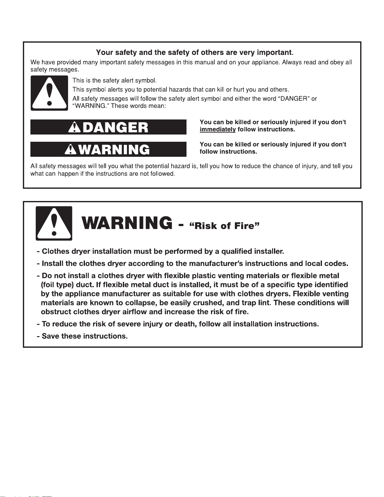
IMPORTANT SAFETY INSTRUCTIONS
WARNING: To reduce the risk of re, electric shock, or injury to persons when using the dryer, follow basic precautions,
including the following:
■ Read all instructions before using the dryer.
■ Do not place items exposed to cooking oils in your dryer.
Items contaminated with cooking oils may contribute to
a chemical reaction that could cause a load to catch re.
To reduce the risk of re due to contaminated loads, the
nal part of a tumble dryer cycle occurs without heat
(cool down period).
WARNING: Avoid stopping a tumble dryer before the end
of the drying cycle unless all items are quickly removed
and spread out so that the heat is dissipated.
■ Do not dry articles that have been previously cleaned
in, washed in, soaked in, or spotted with gasoline,
dry-cleaning solvents, other ammable, or explosive
substances as they give off vapors that could ignite or
explode.
■ Do not allow children to play on or in the dryer. Close
supervision of children is necessary when the dryer is
used near children.
■ Before the dryer is removed from service or discarded,
remove the door to the drying compartment.
■ Do not reach into the dryer if the drum is moving.
■ This appliance is not intended for use by persons
(including children) with reduced physical, sensory
or mental capabilities, or lack of experience and
knowledge, unless they have been given supervision
or instruction concerning use of the appliance by a
person responsible for their safety.
■ That adequate ventilation has to be provided to avoid
the back ow of gasses into the room from appliances
burning other fuels, including open res.
■ Do not dry unwashed items in the tumble dryer.
■ Items that have been soiled with substances such as
cooking oil, acetone, alcohol, petrol, kerosene, spot
removers, turpentine, waxes and wax removers should
be washed in hot water with an extra amount of
detergent before being dried in the tumble dryer.
■ Remove all objects from pockets such as lighters and
matches.
■ That exhaust air must not be discharged into a ue
which used for exhausting fumes from appliances
burning gas other fuel.
■ That the appliance must not be installed behind a
lockable door, a sliding door or a door with a hinge on
the opposite side to that of the tumble dryer, in such
a way that a full opening of the tumble dryer door is
restricted.
■ If the power supply cord damaged, it must replaced by
manufacturer or its service agent or similarly qualied
person in order to avoid a hazard.
■ Do not install or store the dryer where it will be
exposed to the weather.
■ Do not tamper with controls.
■ Do not repair or replace any part of the dryer
or attempt any servicing unless specically
recommended in this Use and Care Guide or in
published user-repair instructions that you understand
and have the skills to carry out.
■ Do not use fabric softeners or products to eliminate
static unless recommended by the manufacturer of the
fabric softener or product.
■ Do not use heat to dry articles containing foam rubber
or similarly textured rubber-like materials.
■ Clean lint screen before or after each load.
■ Keep area around the exhaust opening and adjacent
surrounding areas free from the accumulation of lint,
dust, and dirt.
■ The interior of the dryer and exhaust vent should be
cleaned periodically by qualied service personnel.
■ See installation instructions for grounding
requirements.
SAVE THESE INSTRUCTIONS
Specifications
Capacity: Maximum dry load size which can be treated in a
cycle, as declared by the manufacturer.
Rated Voltage
Rated Frequency
Rated Current
Max. drying capacity
(dry loads)
*IEC Capacity
*IEC Capacity is the maximum capacity of dry linens and textiles which the manufacturer declares can be treated in a specic cycle.
120 V
60 Hz
12 A
7.0 Kg
3.4 kg
3
Installation Instructions
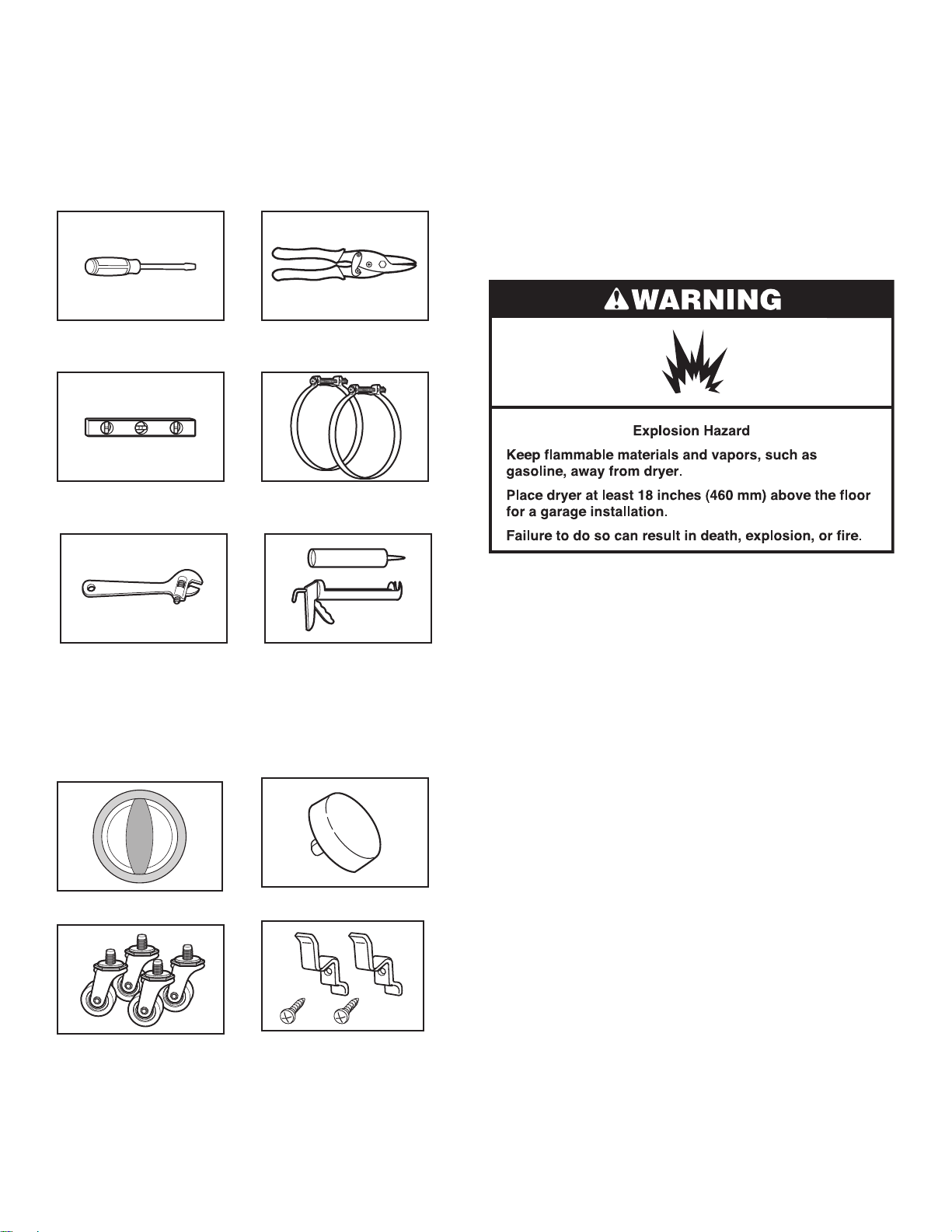
Tools and Parts
Tools needed
Gather the required tools and parts before starting installation.
Read and follow the instructions provided with any tools
listed here.
Flat-blade screwdriver Tin snips (new vent
installations)
Level Vent clamps
Parts needed
Check local codes, existing electrical supply and venting, and
see “Venting Requirements” and “Electrical Requirements” before
purchasing parts.
■ Mobile home installations require metal exhaust system
hardware.
■ Permanent installations require 4 dryer feet
For information on ordering, please refer to “Assistance or
Service” on the back cover. You may also contact the dealer from
whom you purchased your dryer.
Location Requirements
Adjustable wrench that opens
to 1" (25 mm) or hex-head
socket wrench
Caulking gun and compound
(for installing new exhaust vent)
Parts supplied
Remove parts package from the dryer drum. Check that all parts
listed are included.
Cycle control knob Start button
You will need
■ A location that allows for proper exhaust installation. See
“Venting Requirements.”
■ A 120 V, 60 Hz., AC only, 15 or 20 A circuit.
■ A grounded electrical outlet located within 2 ft (610 mm) of
either side of the dryer. See “Electrical Requirements.”
■ A sturdy oor to support the dryer weight (dryer and load)
of 115 lbs (52 kg). The combined weight of a companion
appliance should also be considered.
■ A level oor with a maximum slope of 1" (25 mm) under
entire dryer.
Do not operate your dryer at temperatures below 45ºF (7ºC). At
lower temperatures, the dryer might not shut off at the end of an
automatic cycle. Drying times can be extended.
The dryer must not be installed or stored in an area where it will
be exposed to water and/or weather.
Check code requirements. Some codes limit, or do not permit,
installation of the dryer in garages, closets, mobile homes, or
sleeping quarters. Contact your local building inspector.
Casters (4) Cord brackets (2) and
screws (2)
4
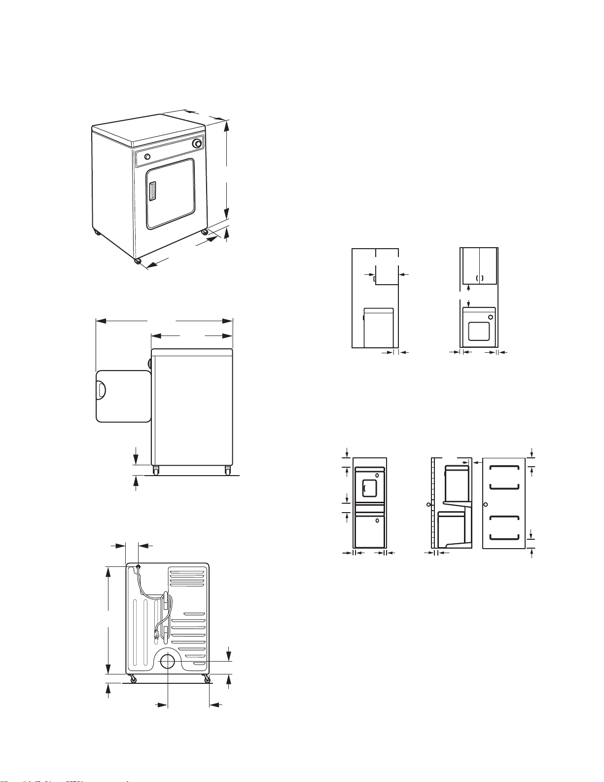
Installation Clearances
AB
(25 mm)
The location must be large enough to allow the dryer door to
open fully.
Dryer Dimensions
Front View
3
/4"*
20
(527 mm)
†
31"
(787 mm)
3
1
237/8"
(606 mm)
†Height with caster is 32½" (826 mm)
Side View
36"
(914 mm)
3
20
/4"
(527 mm)
/4"
(44 mm)
Minimum installation spacing for recessed
area and closet installation
The following dimensions shown are for the minimum spacing
allowed when the dryer is to be operated with, or without, the
Stack Stand Kit. To purchase a Stack Stand Kit, see “Assistance
or Service.”
■ Additional spacing should be considered for ease of
installation and servicing.
■ Additional clearances might be required for wall, door, and
oor moldings.
■ Additional spacing of 1" (25 mm) on all sides of the dryer is
recommended to reduce noise transfer.
■ For closet installation with a door, minimum ventilation
openings in the top and bottom of the door are required.
Louvered doors with equivalent ventilation openings
are acceptable.
■ Companion appliance spacing should also be considered.
Recessed or closet installation - Dryer only
14"*
(356 mm)
18"* (457 mm)
51/2"*
(140 mm)
1"
(25 mm)
1"
1
3
/2"
(89 mm)
1
/4"
29
(743 mm)
13/4"
(44 mm)
Back View
31/4"
(83 mm)
A. Side view - closet or confined area
B. Recessed area
*Most installations require a minimum 5½" (140 mm) clearance
behind the dryer for the exhaust vent with elbows. See “Venting
Requirements.”
Recessed or closet installation - Stacked
12"*
(305 mm)
12"*
(305 mm)
1"
(25 mm)
51/2"
(140mm)
DRYER
WASHER
1"*
1"
(25 mm)
(25 mm)
A B
48 in. *
(309.7 cm )
24 in. *
(154.8 cm )
3"*
(76 mm)
2
2
2
2
3"*
(76 mm)
C
A. Recessed area
B. Side view - closet or confined area
C. Closet door with vents
7
/8"
13/4"
(44 mm)
11
(303 mm)
5
Electrical Requirements
■ 120 V, 60 Hz, AC only, 15 or 20 A fused electrical supply is
required.
■ A time-delay fuse or circuit breaker is recommended.
Check that the fuse or circuit breaker matches the rating
of your line.
■ It is also recommended that a separate circuit serving only this
dryer be provided.
■ Do not use an extension cord.
Venting
Venting Requirements
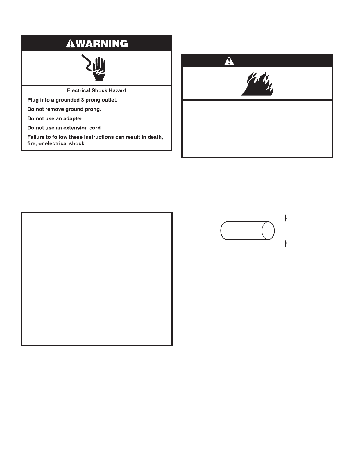
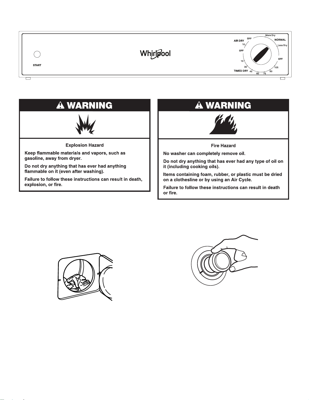
WARNING
Fire Hazard
Use a heavy metal vent.
Do not use a plastic vent.
Do not use a metal foil vent.
Failure to follow these instructions can result in death
or fire.
WARNING: To reduce the risk of re, this dryer MUST BE
EXHAUSTED OUTDOORS.
IMPORTANT: Observe all governing codes and ordinances.
Dryer exhaust must not be connected into any gas vent, chimney,
wall, ceiling, attic, crawlspace, or a concealed space of a
building. Only rigid or exible metal vent shall be used
for exhausting.
GROUNDING INSTRUCTIONS
■
For a grounded, cord-connected dryer:
This dryer must be grounded. In the event of malfunction or
breakdown, grounding will reduce the risk of electric shock
by providing a path of least resistance for electric current.
This dryer is equipped with a cord having an equipmentgrounding conductor and a grounding plug. The plug must
be plugged into an appropriate outlet that is properly
installed and grounded in accordance with all local codes
and ordinances.
WARNING: Improper connection of the equipment-
grounding conductor can result in a risk of electric shock.
Check with a qualied electrician or service representative
or personnel if you are in doubt as to whether the dryer is
properly grounded. Do not modify the plug provided with
the dryer: if it will not t the outlet, have a proper outlet
installed by a qualied electrician.
SAVE THESE INSTRUCTIONS
4"
(102 mm)
4" (102 mm) heavy metal exhaust vent
■ Only a 4" (102 mm) heavy metal exhaust vent and clamps
may be used.
■ Do not use plastic or metal foil vent.
Rigid metal vent:
■ Recommended for best drying performance and to avoid
crushing and kinking.
Flexible metal vent: (Acceptable only if it is accessible to
clean)
■ Must be fully extended and supported in nal dryer location.
■ Remove excess to avoid sagging and kinking that may result
in reduced airow and poor performance.
■ Do not install in enclosed walls, ceilings, or oors.
■ The total length should not exceed 7¾ ft. (2.4 m).
NOTE: If using an existing vent system, clean lint from entire
length of the system and make sure exhaust hood is not plugged
with lint. Replace plastic or metal foil vents with rigid metal
or exible metal vents. Review “Vent System Chart” and, if
necessary, modify existing vent system to achieve best drying
performance.
6
Exhaust hoods:
■ Must be at least 12" (305 mm) from ground or any object
that may obstruct exhaust (such as owers, rocks, bushes,
or snow).
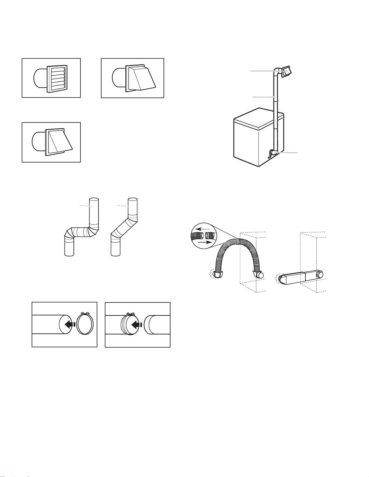
Recommended Style:
Louvered hood Box hood
Acceptable Style:
Angled hood
Elbows
45° elbows provide better airow than 90° elbows.
Good
Better
Plan Vent System
Choose your exhaust installation type
Recommended exhaust installations:
Typical installations vent the dryer from the rear of the dryer.
Other installations are possible.
A
B
C
A. Exhaust hood
B. Flexible metal or rigid metal vent
C. Elbow
Alternate installations for close clearances:
Venting systems come in many varieties. Select the type best
for your installation. Two close-clearance installations are shown.
Refer to the manufacturer’s instructions.
Clamps
■ Use clamps to seal all joints.
■ Exhaust vent must not be connected or secured with screws
or other fastening devices that extend into the interior of the
duct, because they can catch lint. Do not use duct tape.
A B
A. Over-the-top installation
(also available with one offset elbow)
B. Periscope installation
NOTE: The following kits for close clearance alternate
installations are available for purchase. Contact the place of
purchase for further assistance.
■ Over-the-Top Installation:
Part Number 4396028
■ Periscope Installation (for use with dryer vent to wall vent
mismatch):
Part Number 4396037 - for mismatch of 0" (0 mm) to
18" (457 mm)
Part Number 4396011 - for mismatch of 18" (457 mm) to
29" (737 mm)
Part Number 4396014 - for mismatch of 29" (737 mm) to
50" (1.27 m)
7
Determine vent path
■ Select the route that will provide the straightest and most
direct path outdoors.
■ Plan the installation to use the fewest number of elbows
and turns.
■ When using elbows or making turns, allow as much room
as possible.
■ Bend vent gradually to avoid kinking.
■ Use the fewest 90° turns possible.
Determine vent length and elbows needed for
best drying performance
■ Use the “Vent System Chart” below to determine type of vent
material and hood combinations acceptable to use.
NOTE: Do not use vent runs longer than those specied in
the Vent system chart. Exhaust systems longer than those
specied will:
■ Shorten the life of the dryer.
■ Reduce performance, resulting in longer drying times and
increased energy usage.
The “Vent System Chart” provides venting requirements that will
help to achieve the best drying performance.
Vent System Chart
Number of
90º turns or
elbows
0
1
2
Type of vent Box or
louvered
hoods
Rigid metal 36 ft (11 m) 26 ft (7.9 m)
Rigid metal 26 ft (7.9 m) 16 ft (4.9 m)
Rigid metal 16 ft (4.9 m) 6 ft (1.8 m)
Angled
hoods
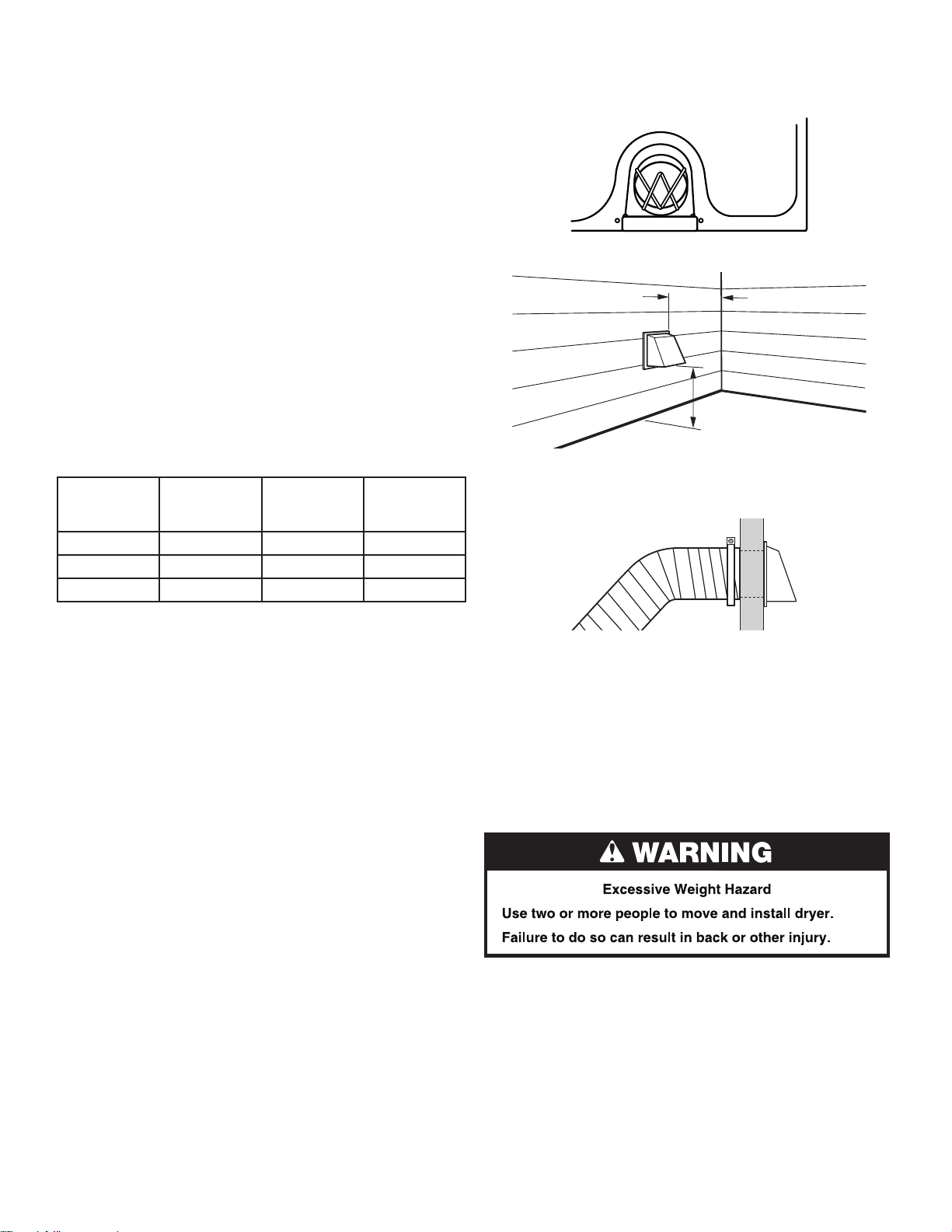
Install Vent System
1. Before installing the vent system, be sure to remove the wire
exhaust guard that is located at the exhaust outlet.
2. Install exhaust hood.
12" min.
(305 mm)
12" min.
(305 mm)
Install exhaust hood and use caulking compound to seal
exterior wall opening around exhaust hood.
3. Connect vent to exhaust hood.
Vent must t inside exhaust hood. Secure vent to exhaust
hood with 4" (102 mm) clamp. Run vent to dryer location.
Use the straightest path possible. See “Determine vent path”
in “Plan Vent System.” Avoid 90º turns. Use clamps to seal
all joints. Do not use duct tape, screws, or other fastening
devices that extend into the interior of the vent to secure vent,
because they can catch lint.
Install Cord Bracket and Casters
Do not move dryer into its nal location until the following steps
have been performed.
Install cord bracket
1. Remove tape from the power cord and the rear panel.
8
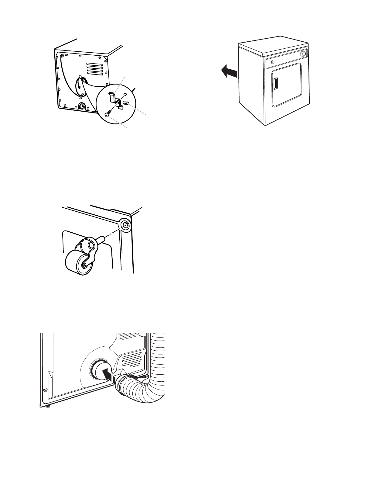
2. Insert cord brackets into slotted holes in rear panel and
B
C
secure with screws provided.
A
2. Move dryer into its nal location. Avoid crushing or kinking
the vent.
A .Cord bracket
B. Slotted hole
C. Screw
NOTE: Power supply cord may be wrapped around the brackets
for storage convenience when dryer is not in use.
Install casters
1. To avoid damaging oor, use a large at piece of cardboard
from dryer carton. Place cardboard under entire back edge
of the dryer.
2. Firmly grasp dryer body and gently lay dryer on cardboard.
3. Screw casters into dryer base at four corners and
tighten securely.
4. Set the dryer upright. In doing so, be certain that the dryer
does not roll away from you.
Connect Vent
1. Connect vent to exhaust outlet.
3. Once exhaust vent connection is made, remove cardboard.
Complete Installation
1. Check that all parts are now installed. If there is an extra part,
go back through the steps to see what was skipped.
2. Check that you have all of your tools.
3. Dispose of/recycle all packaging materials.
4. Check dryer’s nal location. Be sure vent is not crushed
or kinked.
5. Check that dryer is on a level surface.
6. Plug into a grounded 3 prong outlet.
7. Remove lm on the console and any tape remaining on dryer.
Remove tape from lint screen (located on inside back wall
of dryer).
8. Read “Using your Dryer.”
9. Wipe dryer drum interior thoroughly with a damp cloth to
remove any dust.
10. To test the dryer, set the dryer on a full heat cycle
(not an air cycle) for 20 minutes and start the dryer.
If the dryer will not start, check the following:
■ Controls are set in a running or “On” position.
■ Start button has been rmly pressed.
■ Dryer is plugged into a grounded 3 prong outlet.
■ Household fuse is intact and tight, or circuit breaker has
not tripped.
■ Dryer door is closed.
11. When the dryer has been running for 5 minutes, open the
dryer door and feel for heat. If you feel heat, cancel cycle and
close the door.
If you do not feel heat, check the following:
■ Controls are set on a heated cycle, not an air cycle.
NOTE: You may notice an odor when dryer is rst heated. This
odor is common when the heating element is rst used. The odor
will go away.
Using a 4" (102 mm) clamp, connect vent to exhaust outlet
in dryer. If connecting to existing vent, make sure the vent is
clean. Dryer vent must t over dryer exhaust outlet and inside
exhaust hood. Check that vent is secured to exhaust hood
with a 4" (102 mm) clamp.
9
Using Your Dryer
Starting Your Dryer
WARNING: To reduce the risk of re, electric shock, or injury to
persons, read the IMPORTANT SAFETY INSTRUCTIONS before
operating this appliance.
Before using your dryer, wipe the dryer drum with a damp cloth
to remove dust from storing and shipping.
1. Clean the lint screen before each load. See “Cleaning the
Lint Screen.”
2. Load clothes loosely into the dryer and close the door. Do not
pack the dryer. Allow space for clothes to tumble freely.
3. Turn the Cycle Control knob to the recommended cycle for the
type of load being dried. Use the Normal automatic cycle to
dry most heavyweight and medium weight loads. See “Drying,
Cycle, and Temperature Tips.”
4. Press the PUSH TO START button.
Stopping and Restarting
You can stop your dryer anytime during a cycle.
To stop your dryer:
Open dryer door or turn Cycle Control knob to OFF.
NOTE: The Cycle Control knob should point to an Off area when
dryer is not in use.
To restart your dryer:
1. Close the door.
2. Select a new cycle and temperature (if desired).
3. Press the PUSH TO START button.
10
 Loading...