

Whirlpool 780164 Instruction Sheet
INSTALLATION INSTRUCTIONS
for Compactor Motor Switch Kit #780164 and
Replacement Motor Kit
wWARNING
Electrical Shock Hazard
Disconnect power before servicing.
Replace all panels before operating.
Failure to do so can result in death or electrical shock.
These instructions are only applicable for repair of compactors manufactured after 1980.
1. Unplug compactor or disconnect power.
2. Remove motor from compactor.
Freestanding Models:
a. Remove the container drawer.
b. Lay the compactor on either of its sides, using a drop
cloth to protect the finish of the cabinet.
c. Remove the five (5) screws that hold the bottom pan
cover to the base and cabinet.
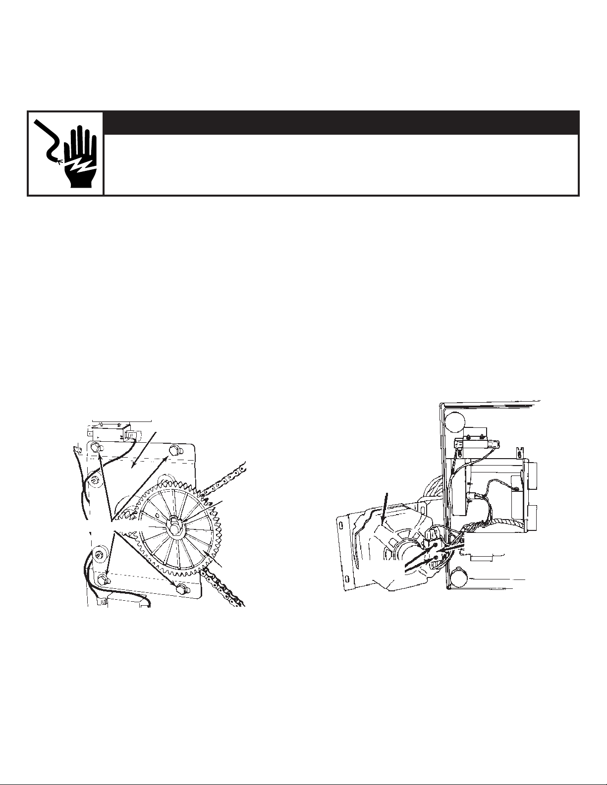
d. Loosen the four (4) bolts or screws that fasten the
drive mount assembly to the compactor frame.
See Figure 1.
e. Remove the clip ring from the drive mount plate shaft
(Figure 1).
Drive mount
assembly
f. Slide the motor mount plate forward and lift the driven
gear and sprocket from the drive mount plate shaft.
g. Remove the four (4) bolts or screws that fasten the
drive mount assembly.
h. The motor and drive mount plate can now be removed
so the switch can be replaced (Figure 2).
IMPORTANT: Do not let motor fall and damage switch
arms during removal.
Mounting bolts (4)
© Whirlpool Corporation 2001
(All Rights Reserved)
Figure 1
Clip ring
Driven gear
Drive
motor
Centrifugal
switch
Mounting
screws
Figure 2
(continued)
Instruction Sheet 675397 Rev. D 2/01
1
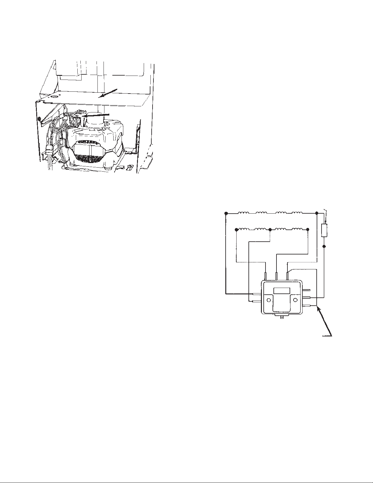
Undercounter Models:
NOTE: When servicing the switch or motor on undercounter
models, the motor backplate and motor cover can be
removed, as shown in Figure 3.
Motor
cover
Centrifugal
switch
Figure 3
3. Remove failed switch (if replacing motor, go
directly to step 5).
a. Disconnect motor and wiring harness leads from
switch terminals.
b. With motor removed, remove the two (2) switch
mounting screws.
4. Install new switch.
a. Mount the new motor switch to the end shield of the
motor with the two screws.
b. Connect motor leads to the new switch.
• Connect yellow lead to terminal “Y“
• Connect brown lead to terminal “4”
• Connect gray lead to terminal “3”
• Connect red lead to terminal “R”
• Connect blue lead to terminal “1”
• Connect white lead to terminal “W”
IMPORTANT: Jumper wire must be connected to
terminals “1” and “2”
c. Connect wire harness leads to the new switch.
• Connect yellow lead to terminal “Y
• Connect gray lead to terminal “3”
• Connect brown lead to terminal “4”
• Connect red lead to terminal “R”
• Connect blue lead to terminal “2”
• Connect white lead to terminal “W”
• Connect orange/black lead (if present) to
terminal “O/BK”
Protector
Red
Blue
Yellow
Gray
Start 1
Brown
Run
Start 2
Jumper
wire
3
Y
Switch
4
W
1R
O/
BK
2
NOTE: Leave jumper wire intact
White
(continued)
675397-D
2
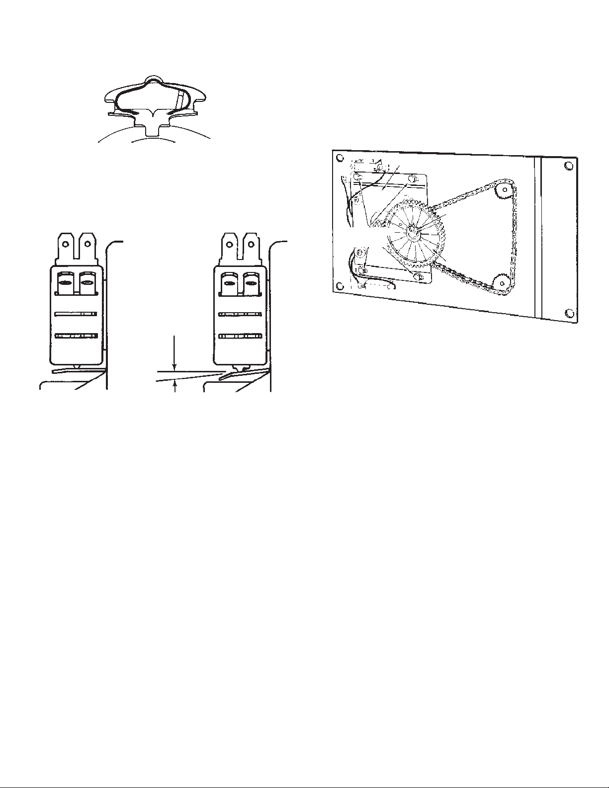
d. The actuating lever should remain seated evenly in the
motor end shield notches and the spring clip should
remain fixed in place in the notch provided in the end
shield. (See Figure 4.)
Figure 4
e. Check actuating lever positions as shown in Figures 5
and 6. With motor stopped, the lever should be in
position shown in Figure 5. With motor running, the
lever should be in position shown in Figure 6.
7. Reassemble compactor.
a. Reassemble compactor in reverse order.
b. Adjust chain tension as evenly as possible and still
allow room to rotate big gear 180°. Allow approximately
1
⁄4" deflection between any two (2) of the three (3)
sprockets. (See Figure 7.)
NOTE: When reassembling the driven gear to the driven
mount shaft, make sure the parts are placed on the drive
mount shaft in correct sequence.
Drive motor assembly
Clip ring
Mounting
nuts (4)
Driven gear
.010 minimum.
Figure 5. Motor idle Figure 6. Motor running
5. Remove old motor.
IMPORTANT: Do not let motor fall and damage switch
arms during removal.
6. Install new motor.
Refer to step 4, c for instructions on how to connect the
compactor’s wire harness to the motor switch.
Figure 7
(continued)
3
675397-D
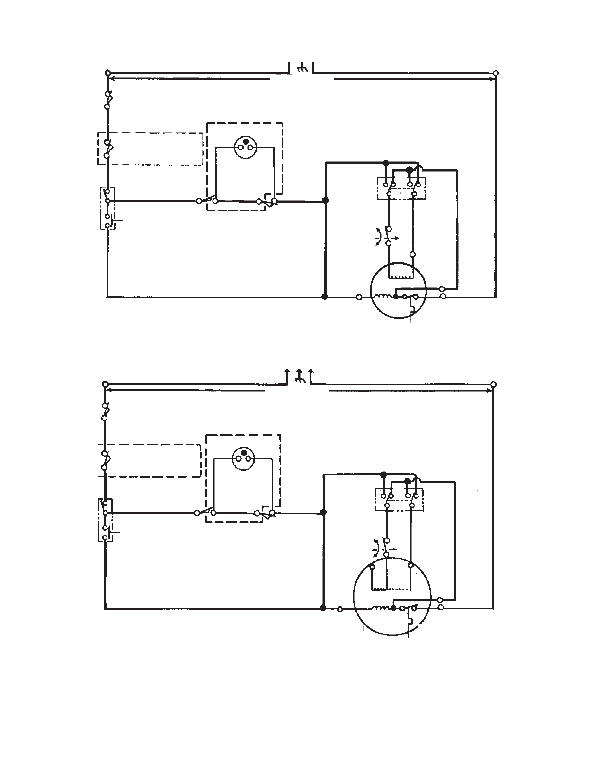
Diagram #1
One Start Winding with Two Reversing Switches
L1
BK
Drawer safety switch
Key lock
safety switch
Run switch
V
Start switch
Y
V
Restart light
BR Y
Top limit
switch
BR
Original motor
Line voltage
Drawer tilt
switch
N
W
Y
Directional
Y
switch
Y
BU
Y
GY
BU
Y
R
GY
Motor
Y
centrifugal
switch
BK
R
R
Start
Run
YY
Y
BU BU
WW
Drive motor
Motor protector
NOTE: Unit may or may not have features indicated by dotted lines. Wiring will be the same in either case.
Replacement motor
L1
BK
Drawer safety switch
Key lock
safety switch
Run switch
V
Start switch
Y
V
Top limit
switch
Restart light
BR
BR
Y
BR
Drawer tilt
switch
Line voltage
Y
#2
Y
#3
#4
GY
Y
BU
BU
Y
R
R
R
Y
Directional
Y
switch
Motor
centrifugal
Y
switch
N
W
675397-D
Remove jumper wire from
terminals 1 and 2 and discard.
Circuit showing unit at normal end of cycle.
Y
4
Y
Y
Drive motor
Run
Start
#1
BU
W
W
Motor protector
(continued)
 Loading...