

Whirlpool 761883306 User Manual
- --
/
n, /
/
-
761883306
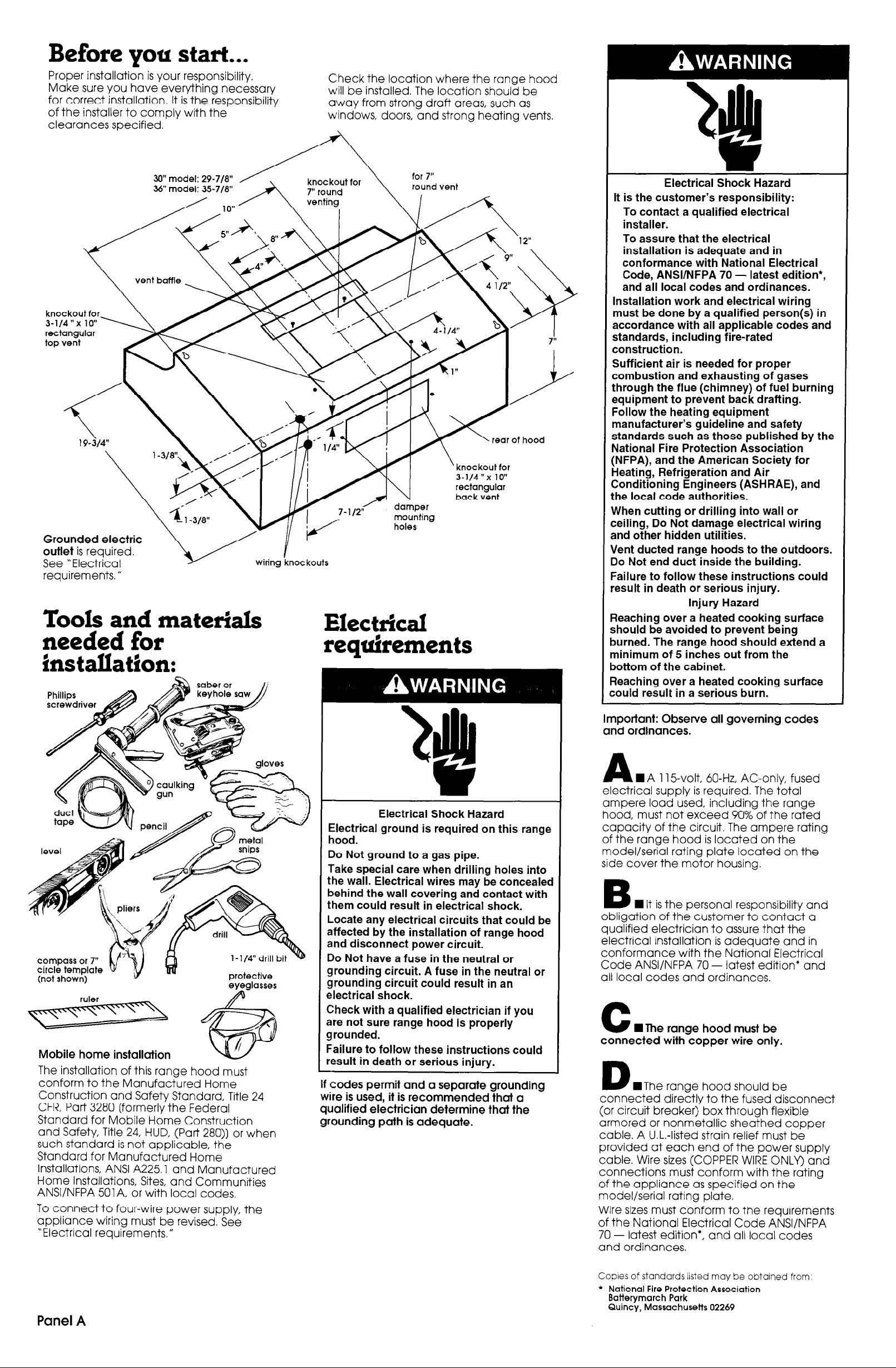
Before you start...
Proper installation is your responsibility.
Make sure you have everything necessary
for correct installation. It is the responsibility
of the installer to comply with the
clearances specified.
Check the location where the range hood
will be installed The location should be
away from strong draft areas, such as
windows, doors, and strong heating vents.
30” model: 29-7/8”
knockout for
\‘l-318”
Grounded electric
outlet is required.
See “Electrical
requirements. ”
/
wiring knockouts
Tools and materials
needed for
installation:
mounting
holes
Electrical requirements
Electrical Shock Hazard
It is the customer’s responsibility:
To contact a qualified electrical
installer.
To assure that the electrical
installation is adequate and in
conformance with National Electrical
Code, ANSVNFPA 70 - latest edition*,
and all local codes and ordinances.
Installation work and electrical wiring
must be done by a qualified person(s) in
accordance with all applicable codes and
standards, including fire-rated
construction.
Sufficient air is needed for proper
combustion and exhausting of gases
through the flue (chimney) of fuel burning
equipment to prevent back drafting.
Follow the heating equipment
manufacturer’s guideline and safety
standards such as those published by the
National Fire Protection Association
:NFPA), and the American Society for
Heating, Refrigeration and Air
Conditioning Engineers (ASHRAE), and
:he local code authorities.
When cutting or drilling into wall or
:eiling, Do Not damage electrical wiring
and other hidden utilities.
ilent ducted range hoods to the outdoors.
IO Not end duct inside the building.
-ailure to follow these instructions could
,esult in death or serious injury.
Injury Hazard
?eaching over a heated cooking surface
should be avoided to prevent being
turned. The range hood should extend a
ninimum of 5 inches out from the
Bottom of the cabinet.
qeaching over a heated cooking surface
:ould result in a serious burn.
I -3 \ A
compass or 7”
circle template w
(not shown)
Mobile home installation
The installation of this range hood must
conform to the Manufactured Home
Construction and Safety Standard, Title 24
CFR, Part 3280 [formerly the Federal
Standard for Mobile Home Construction
and Safety, Title 24, HUD, (Part 280)) or when
such standard is not applicable, the
Standard for Manufactured Home
Installations, ANSI A225 1 and Manufactured
Home Installations, Sites, and Communities
ANSVNFPA 501 A, or with local codes,
To connect to four-wire power supply, the
appliance wiring must be revised. See
“Electrical requirements.”
v flu
l-1/4” drill bit
protective
eyeglasses
Electrical Shock Hazard
Electrical ground is required on this range
hood.
Do Not ground to a gas pipe.
Take special care when drilling holes into
the wall. Electrical wires may be concealed
behind the wall covering and contact with
them could result in electrical shock.
Locate any electrical circuits that could be
affected by the installation of range hood
and disconnect power circuit.
v
Do Not have a fuse in the neutral or
grounding circuit. A fuse in the neutral or
grounding circuit could result in an
electrical shock.
Check with a qualified electrician if you
are not sure range hood is properly
grounded.
Failure to follow these instructions could
result in death or serious injury.
If codes permit and a separate grounding
wire is used, it is recommended that a
qualified electrician determine that the
grounding path is adequate.
Important: Observe all governing codes
and ordinances.
A
WA 115volt, 60-Hz, AC-only, fused
electrical supply is required. The total
ampere load used, including the range
hood, must not exceed 90% of the rated
capacity of the circuit. The ampere rating
of the range hood is located on the
model/serial rating plate located on the
side cover the motor housing.
n
B
obligation of the customer to contact a
qualified electrician to assure that the
electrical installation is adequate and in
conformance with the National Electrical
Code ANSVNFPA 70 - latest edition* and
all local codes and ordinances.
C
connected with copper wire only.
D
connected directly to the fused disconnect
(or circuit breaker) box through flexible
armored or nonmetallic sheathed copper
cable. A U.L.-listed strain relief must be
provided at each end of the power supply
cable. Wire sizes (COPPER WIRE ONLY) and
connections must conform with the rating
of the appliance as specified on the
model/serial rating plate.
Wire sizes must conform to the requirements
of the National Electrical Code ANSI/NFPA
70 - latest edition*, and all local codes
and ordinances.
It is the personal responsibility and
W The range hood must be
WThe range hood should be
Panel A
Copies of standards listed may be obtained from:
l
National Fire Protection Association
Batterymarch Park
Quincy, Massachuseits 02269

Venting requirements
Horizontal Wall Venting
Now start...
With range hood in kitchen.
’ f
f
I
Aib
Fire Hazard
Venting system must terminate to the
outside.
Do Not vent exhaust air into spaces
within walls or ceilings or into attics,
crawl spaces or garages.
Use metal duct only.
Do Not use four-inch laundry-type wall
caps.
Do Not use plastic ductwork.
Flexible metal duct is Not recommended.
If it is used, calculate each foot of flexible
metal duct as two feet of straight duct.
Flexible metal elbows count twice as
much as standard elbows.
Do Not use to exhaust hazardous or
explosive materials and vapors.
Failure to follow these instructions could
result in a fire.
3-l/&x 10”
throuah the wall
7” min. diameter
round ductwork
elbow
3-1/4”x 10” to round
ductwork transition
Figure 3
*I...
. -.-m..---l
: :‘I-’
I I*\
I I
‘.{ a.
:.--
l t
-:,,--’
A
.:
J
I cap
wall cap
l \
Slide cardboard or hardboard under range
before moving range across floor to
prevent damaging floor covering.
Cover countertop, cooktop or set-in range
with a thick, protective covering to prevent
damaging countertop.
1 Put on safety glasses and gloves.
I
n
2
range from cabinet opening to provide
easier access to upper cabinet and rear
wall. Put a thick, protective covering over
cooktop, set-in range or countertop to
protect from damage or dirt
3
(roof or wall venting or non-venting) you
need to use. This range hood is shipped for
non-vented installation.
If non-venting (recirculating) installation is
desired, follow instructions on Panel D.
Disconnect and move freestanding
H Determine which venting method
Vented installation
vent baffle
Ductwork needed for insfallofion is not
included. Wall or roof caps used must have
backdrafl damper.
Determine which outside venting method
needs to be used NOTE: If a non-vented
(recirculating) installation is desired, follow
instructions on Panel D.
The length of the ductwork and number of
elbows should be kept to a minimum to
provide efficient performance. The size of
the ductwork should be uniform. Do Not
install two elbows together. Use duct tape
to seal all joints in the ductwork system.
Ductwork can terminate either through the
roof or wall. Use caulking to seal exterior
wall or roof opening around exhaust hood.
For the most efficient and quiet operation, it
is recommended that the range be vented
vertically through the roof through 7” round
ductwork.
Figures l-4 show common venting methods
and what types of materials are needed.
Vertical Roof Venting
7” round
through t
roof
roof cap
Figure 4
Recommended ductwork length
Use 3-l /4” x 10” or 7” ductwork with a
m’aximum length of 26 feet for ductwork
system. For best performance, use no more
Wan three 90” elbows. To calculate the
length of system you need, add the
equivalent feet for each ductwork piece
used in the system. See the following
examples.
3- l/4” x 10” ductwork system
3 - 114” x 10”
elbow
H- 6 ft.
0 3 -7
u
Maximum 1 - 90” elbow IenLth
* ft’
8 feet straight
1 - wall cap
Length of
3- l/4” x 10” system
wall cap
= = 26 5ft feet
= 8ft.
= Oft.
= 13 ft.
Recommended standard fittings
.‘Q:,
F
W Remove screws from vent baffle on
4
top of range hood. Remove vent baffle.
top of range hood so that the word
“Vented” is facing up. Fasten vent baffle
with screws.
in
damper locatec?as far from hood
as possible
Figure 1
Vertical Roof Venting
3-114” x 10”
through the roof
ro/f cap
3-114” x 10”
damper
3-114” x 10” 90”
elbow = 5 ft.
3-114” x 10” flat 3-l/4” x 10” wail
elbow = 12 ft.
cap=oft.
7” ductwork system
/
3-1/4”x 10”
to 7”
transition
Maximum length
1 - transition
2 - 90” elbows
8 feet straight
1 - wall cap
Length of 7” system = 22.5 ft
= 26 feel
= 4,5 ft
=lO ft.
= 8 ft.
= 0 ft.
Recommended standard fittings
knockouts
n
6
opening (top or rear) to be used.
For rectangular venting, remove only the
3-l/4” x 10” rectangular opening knockout.
For round ductwork venting through roof,
remove both opening knockouts.
Remove knockout from the wiring
terminal
box
Panel B
Figure 2
3-114” x IO” to 3-114” x 10” to 7” 7” to 3-114” x 10”
7” = 4.5 ft. 90” elbow = 5 ft. 90” elbow = 9 ft.
90” elbow = 7” to 3-114”
5 ft.
xlO”=lft.
;“,“;lbow = I’;wtizll cap
. .
n
Remove terminal box cover
range hood
from
 Loading...