

Whirlpool 759105-U User Manual
IMPORIANr
Instai/er: Leave Instaiiat/oo Instructions
Homeowner. Keep insto,lotion instructions
Save !n.staliat,on lnstructions~for loco)
With the homeow.oer
lor future reference
electrical inspectors use.
InstallaHon Instructions
Part No. 759105-U
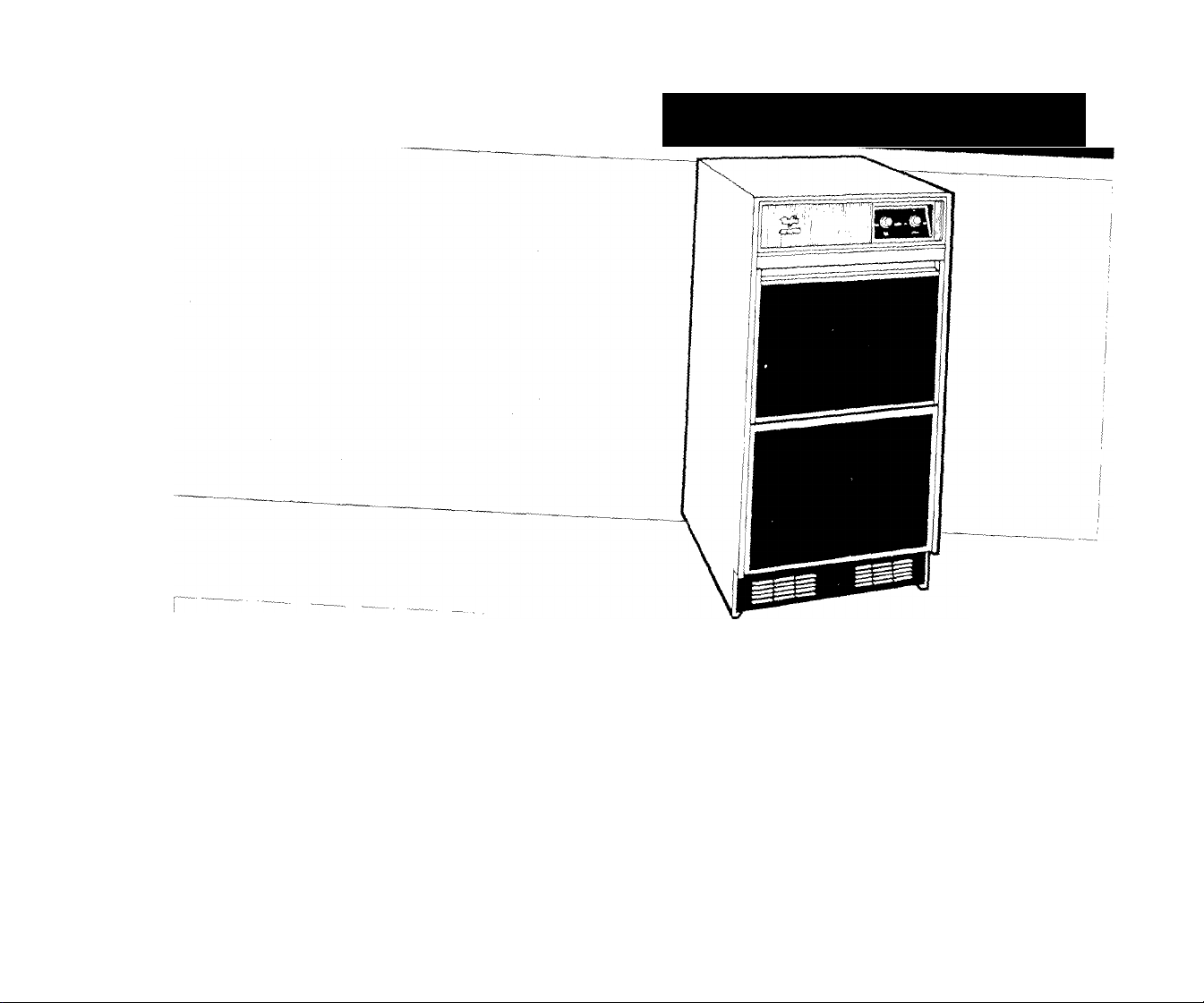
Ice Maker
WhirWoI
Before you start...
Proper insîallotion is your responsibility.
Make sure you have everything
necessary for correct installation, It
is the customer's responsibility to
contact a qualified installer to as
sure that the plumbing and electri
cal installations are adequate and
meet all local codes and ordinan
ces,
Proper electrical supply, water
supply lines, and floor drain or
sump pump must be available or
must be installed, as specified,
within the shaded area, (See
"Electrical", "Water", and "Drain re
quirements"' sections.) Plumbing
and wiring should not cross in front
of fhe ice maker motor. Wiring
should not pass through the drain
area.
Important: Observe all govern
ing codes and ordinances.
Electrical ground is required (See
"Electrical requirements".)
Do Not close in the front of the ice
maker. The ice maker cannot work
properly if the airflow to the front
of the ice maker is blocked.
Compliance with National Sanita
tion Foundation standards requires
that this type of product be
sealed to the floor at the bottom
rail in order to prevent contamina
tion from spills or vermin. Therefore,
we recommend that when install
ing this product you seal it to the
floor in accordance with those
standards. A silicone-type sealer is
recommended.
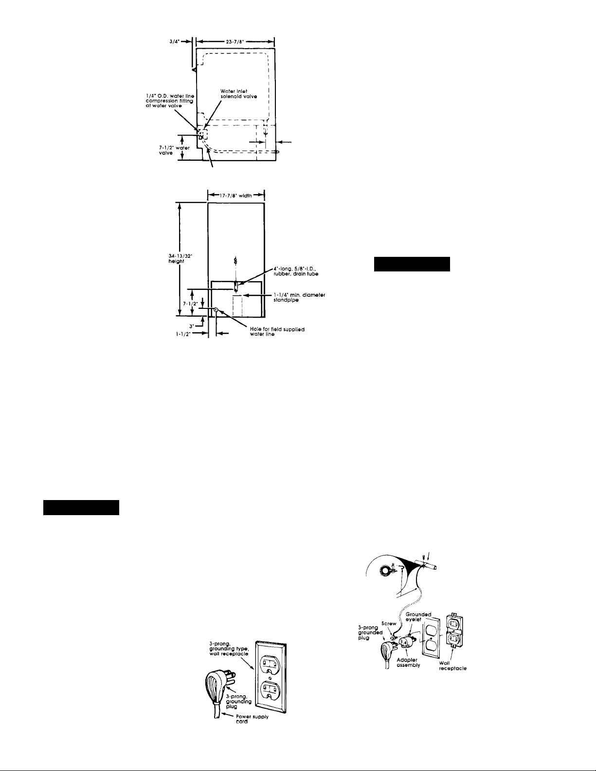
Right side view
Bend field supplied water line
to connect lo water valve fitting
Figure 1
Check the location where the ice maker
will be installed. The location must
provide;
• Easy access to water, electricity and
drainage lines,
• Protection from wind, weather,
dripping or spraying water, and other
harmful elements,
• Protection from cold temperatures to
prevent the water inlet valve and
drain from freezing,
• Good ventilation and unobstructed
airflow to the front of the ice maker.
• Room to fully open the ice maker
door.
• Room to move the cabinet forward for
servicing, it necessary.
The unit may be enclosed around the
sides, top and rear of ice maker.
Protection from weather: Do Not store or
operate the ice maker below 55‘^F or
above 1 IChF. For best results, operate
the ice maker at temperatures between
70°F to 90^F,
Drain system requires either a gravity,
floor-drain system or a drain pump (see
"Dram requirements'") to lift the water to
an existing drain, A 1-1/4" min, diameter
standpipe or 5/8" I.D, minimum drain
tube to an open drain is required.
^WARNING
Electrical Shock Hazard
Do Not let electrical wiring and
components contact the drain
hose or any plumbing materials.
Failure to follow these instructions
could result in fire, electrical
shock or other personal injury.
Read and follow the "Electrical
requiremehts", "Water requirements"
and "Drain requirements" sections
before installing the ice maker.
Shipboard installatior^s:
Ice makers installed in ships require a
water deflector (available from your
local authorized parts distributor).
The deflector keeps the water that
flows over the evaporator from
spilling into the storage bin area.
Install deflector according to the
instructions provided with the
deflector kit.
Electrical
requirements
AWARNING
Electrical Shock Hazard
• Electrical ground is required on
this appliance.
• Check with a qualified
electrician if you are in doubt as
to whether the appliance Is
properly grounded. Do Not
modify or remove the power
supply cord plug. If it will not fit
the outlet, have a proper outlet
Installed by a qualified
electrician.
• Improper connection of the
equipment-grounding
conductor can result in a risk of
electrical shock.
• Do Not use an extension cord
with this appliance.
• Do Not have a fuse in the neutral
or grounding circuit.
• Do Not connect to electrical
supply until appliance is
permanently grounded.
Failure to follow these instructions
could result in a fire, electrical
shock, or other personal injury.
A 120-volt, 60-Hz, AC only, 15-
ampere, fused, electrical supply is
required. Time-delay fuse or circuit
breaker is recommended, it is
Panel A
recommended that a separate
circuit serving only this appliance
be provided.
It the personal responsiPility and
obligation of the customer to
contact a qualified electrician to
assure that fhe electrical installation
is adequate and in conformance
with the National Electrical Code
ANSI/NFPA 70 latest edition, and all
local codes and ordinances.
Recommended grounding
method
For your personal safety, this
appliance must be grounded. This
appliance is equipped with a power
supply cord having q 3-prong,
grounding plug. To minimize possible
shock hazard, the cord must be
plugged into a mating, 3-prong,
grounding-type wall receptacle,
grounded in accordance with the
National Electrical Code ANSI/NFPA
70-latest edition, and local codes
and ordinances. (See Figure 2.)
If a mating wall receptacle is not
available, it is the personal
responsibility and obligation of the
customer to have a properly
grounded, 3-prong, wall receptacle
installed by a qualified electrician.
Figure 2
Temporary grounding method
If changing and properly grounding
the wall receptacle is impossible and
where local codes permit (consult
your electrical inspector), a
temporary adapter may be plugged
into the existing, 2-prong, wall
receptacle to mate with the
3-prong, power supply cord,
THIS, HOWEVER, IS NOT
RECOMMENDED.
If this is done, you must connect a
separate, copper, grounding wire
(No, 18 minimum) to a grounded,
cold water pipe’ by means of a
clamp and then to the external
grounding connector screw.
connect to a gas supply pipe or hot
water pipe.
(See Figure 3.)
Ground clamp
must be tight
on pipe
Ground wire
(# IBmInimum)
Power supply cord
Do Not
Ground assembly
(attach to grounded
cold water pipe)
\
Electrically
grounded cold
water pipe (remove
paint, etc.)
Figure 3
■ Grounded, cold water pipe must have
metal conrinuity to electrical ground and not
be interrupted by plastic, rubber, or other
electrical insulating connectors such as hoses,
fittings, washers or gaskets (including water
meter or pump). Any electrical insuiatinQ
connector should be jumped as shown with a
length of No, 4, copper wire securely
clamped to bare metal at both ends.
 Loading...