

Whirlpool 4PLSQ8000JQ Installation Instructions
Table of Contents
Introduction
Pages 2 - 3
Requirements
Page 4
Installation steps
Pages 5 - 8
Installation
Instructions
Part No. 8318506
Important:
Read and save these
instructions.
220-volt, 60-Hz
Washer
Important:
• Installer: Leave Installation Instructions with the
homeowner.
• Homeowner: Keep Installation Instructions for future
reference.
• Save Installation Instructions for local electrical inspector’s
use.
Home Appliances
®
2 - 3
4
5 - 8
220 60
:
• : .
• :
.
•
.
:
.
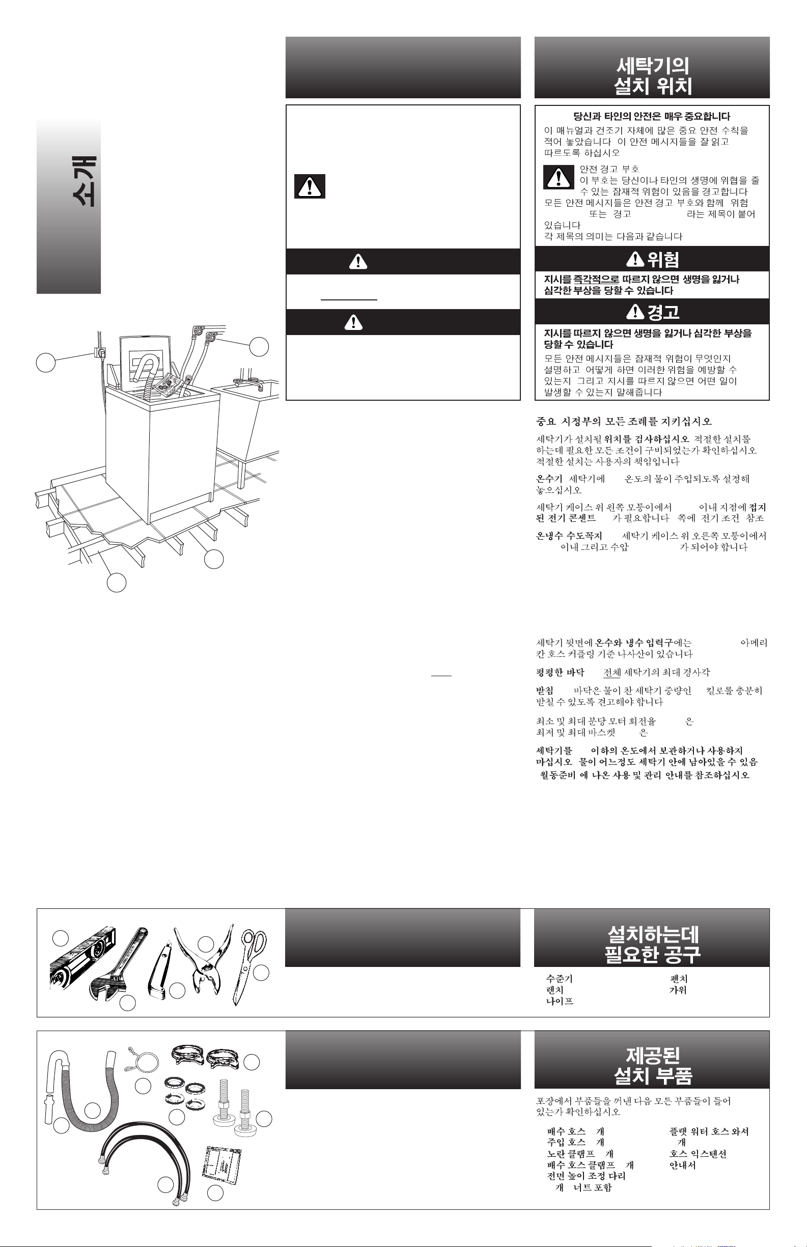
Parts supplied for installation
Tools needed
for installation
2
Location
of washer
Introduction.
A
A
A. level
B. wrench
C. utility knife
D. pliers
E. scissors
A. 1 drain hose
B. 2 inlet hoses
C. 1 yellow clamp
D. 2 drain hose clamps
E. 2 front leveling legs
with nuts
F. 4 flat water hose
washers
G. 1 hose extension
H. literature package
Important: Observe all governing codes and
ordinances.
Check location where washer will be installed. Make sure you
have everything necessary for correct installation. Proper
installation is your responsibility.
Water heater: Set to deliver 60°C (140°F) water to washer.
Earthed electrical outlet (A) is required within 152 cm
(5 feet) of upper left corner of washer cabinet. See “Electrical
requirements,” Page 4.
Hot and cold water faucets (B): Must be within 122 cm
(4 feet) of the upper right corner of the washer cabinet and
provide water pressure 34.5-689.6 kPa (5-100 psi).
B
Remove parts from packages. Check that all parts were included.
B
C
D
A
B
C
D
E
F
G
H
E
D
C
The hot and cold water inlets on the back of the washer have
3/4 — 11-1/2 American hose coupling standard threads.
Level floor (C): Maximum slope under entire
washer — 2.5 cm
(1 inch).
Support (D): Floor must be sturdy enough to support washer
weight (with water) of 143 kilograms (315 pounds).
The minimum and maximum motor rotation per minute (R.P.M.)
is 1140-1725 R.P.M. The minimum and maximum basket R.P.M.
is 423-640 R.P.M.
Do Not store or operate washer below 0°C (32°F) (some
water may remain in washer).
See Use & Care Guide for “Winterizing” information.
.
.
.
.
.
" "
(DANGER)
" " (WARNING)
.
:
.
.
,
,
.
Your safety and the safety of
others are very important.
We have provided many important safety messages in
this manual and on your appliance. Always read and obey
all safety messages.
WARNING
This is the safety alert symbol.
This symbol alerts you to potential hazards that
can kill or hurt you and others.
All safety messages will be preceded by the safety alert
symbol and the word “DANGER” or “WARNING”. These
words mean:
All safety messages will tell you what the potential hazard
is, tell you how to reduce the chance of injury, and tell
you what can happen if the instructions are not followed.
You can be killed or seriously injured if you
don’t immediately
follow instructions.
You can be killed or seriously injured if you
don’t follow instructions.
DANGER
: .
.
.
.
: 60°C
.
152cm
(A) . 4 “ ” .
(B):
122cm 34.5-689.6 kPa .
3/4 — 11-1/2
.
(C): — 2.5cm.
(D): 143
.
(R.P.M.) 1140-1725 R.P.M.
R.P.M. 423-640 R.P.M.
0°C
( ).
“
” .
A.
B.
C.
D.
E.
A. (1 )
B. (2 )
C. (1 )
D. (2 )
E.
(2 ) ( )
F.
(4 )
G.
H.
.
3
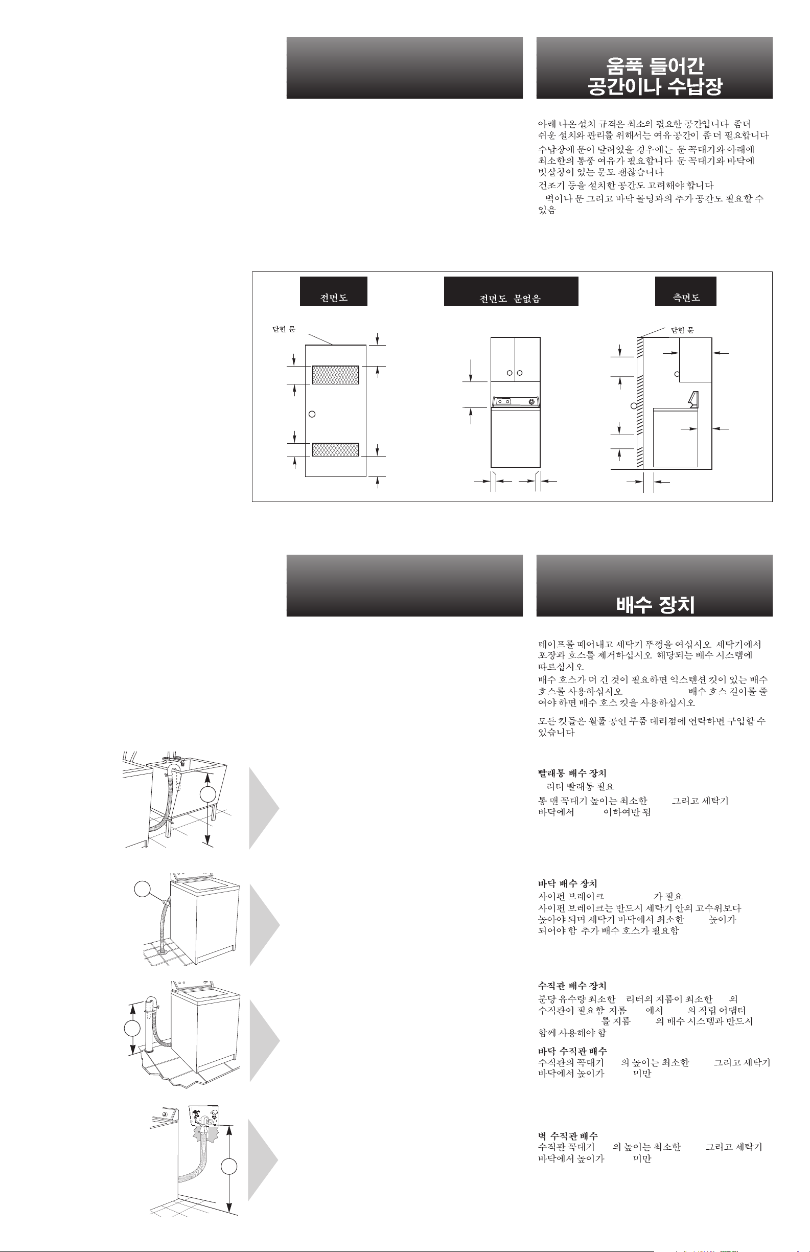
Front view (door not shown)
( )
Side view
The installation dimensions shown are the minimum spaces
allowable. Additional spacing should be considered for ease of
installation and servicing.
If closet door is installed, the minimum air openings in top and
bottom of door are required. Louvered doors with air openings in
top and bottom are acceptable.
Companion appliance spacing should be considered.
* Additional clearances for wall, door and floor moldings may be
required.
Front view
Untape and open washer lid. Remove packages and hoses from
washer. Follow directions for your type of drain system.
If a longer drain hose is needed, use drain hose extension kit
(Part No. 285702). If drain hose must be shortened, use drain
hose kit (Part No. 285442).
All kits are available from Whirlpool-authorized parts distributors.
Laundry tub drain system:
Needs a 76-liter (20-gallon) laundry tub.
Top of tub must be at least 86 cm (34 inches) high and no higher
than 183 cm (72 inches) from bottom of washer (A).
Standpipe drain system:
Needs a 5-cm (2-inch) minimum diameter standpipe with
minimum carry-away capacity of 64 liters (17 gallons) per
minute. A 5-cm (2-inch) diameter to 2.5-cm (1-inch) diameter
standpipe adapter, Part No. 3363920 must be used with 2.5-cm
(1-inch) diameter drain system.
Floor standpipe drain:
Top of standpipe (C) must be at least 99 cm (39 inches) high and
no higher than 183 cm (72 inches) from bottom of washer.
Floor drain system:
Requires a siphon break, Part No. 285320 (B). Siphon break
must be above high-water level in washer, at least 71 cm
(28 inches) from bottom of washer. Additional drain hose will be
needed.
Wall standpipe drain:
Top of standpipe (D) must be at least 99 cm (39 inches)high and
no higher than 183 cm (72 inches) from bottom of washer.
Recessed area
or closet
Drain system
closet door
7.6 cm (3")
7.6 cm (3")
155 cm
2
(24 in2)
310 cm
2
(48 in2)
*0 cm
(*0")
*0 cm
(*0")
43.2 cm (17")
closet door
310 cm
2
(48 in2)
35.6 cm
max.
(14" max.)
10.2 cm
(4") min.
155 cm
2
(24 in2)
2.5 cm min.
(1" min.)
A
B
C
D
.
.
,
.
.
.
*
.
.
.
.
(Part No. 285702).
(Part No. 285442).
.
:
76
.
86 cm (A)
183 cm .
:
64 5cm
. 5 cm 2.5 cm
(Part No. 3363920) 2.5 cm
.
:
(C) 99 cm
183 cm .
:
(siphon break) . Part No. 285320 (B).
71 cm
. .
:
(D) 99 cm
183 cm .
 Loading...