

Page 1
273 Branchport Avenue
Long Branch, NJ 07740 Thank you for using our products.
(800) 631-2148
www.wheelockinc.com
INSTALLATION INSTRUCTIONS
PAGING SPEAKERS WITH 25V/70V TRANSFORMER
Use this product according to this instruction manual. Please keep this instruction manual for future reference.
MODELS: ST-B4, ST-C8, ST-C8V, ST-C8M AND ST-C8MV
DESCRIPTION:
Wheelock Paging Speakers are ready to be installed assemblies consisting of a loudspeaker, round white grille, and a combination
25V/70V line matching transformer. ST-B4 includes a plastic surface mount housing. ST-C8, ST-C8V, ST-C8M and ST-C8MV
include a round flush grille. ST-C8V and ST-C8MV include a recessed volume control. ST-C8 refers to all models for specification
and installation purposes. The volume attenuation will reduce output by 20dB.
The ST-C8 models are 8" ceiling mount speakers, used primarily in office areas, hallways and other low to medium noise level areas.
The ST-B4 is a 4" surface wall mount speaker used in the same areas, when it is not convenient to mount ceiling speakers.
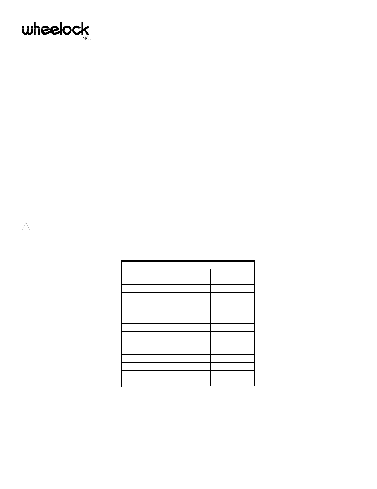
The areas ambient noise level will determine the speaker power (volume) tap chosen for a specific installation. Table 1 shows typical
noise levels in various locations.
WARNING: 1) THESE DEVICES ARE NOT INTENDED FOR USE IN HAZARDOUS LOCATIONS AS DEFINED BY
THE NATIONAL ELECTRICAL CODE (NEC) AND BY THE NATIONAL FIRE PROTECTION ASSOCIATION (NFPA).
2) THESE DEVICES ARE DESIGNED FOR INDOOR USE ONLY. DO NOT EXPOSE TO RAIN OR MOISTURE.
Table 1: Typical Noise Levels
Location dB
Assembly Line 75
Supermarket 75
Transportation - -- Waiting Room 75
Office (Noisy) 70
Shipping/Warehouse 70
Restaurant 70
Department Store 65
Bank (Public Area) 65
Office (Quiet) 55
Office/Doctors - -- Waiting Room 55
Hotel Lobby 55
Doctors Exam Room 55
NOTE: The power taps chosen should result in the paging level exceeding the areas ambient noise level by at least 6dB, and the
background music level exceeding the ambient noise level by at least 3dB.
Copyright 1999 Wheelock, Inc. All rights reserved.
P81832 J
Sheet 1 of 6
Page 2
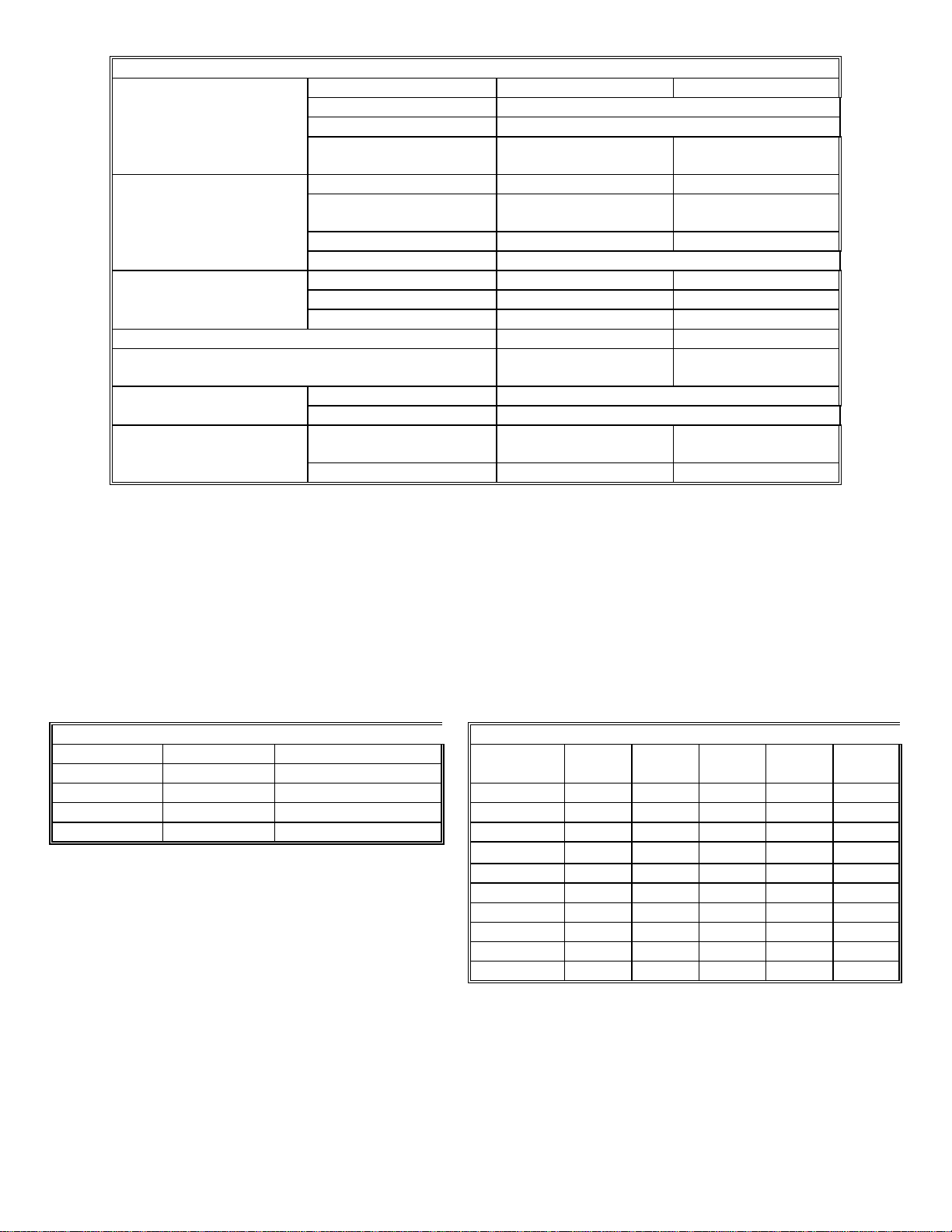
Table 2: Specifications
Cone Diameter ST-C8 Models ST-B4 - 4"
Voice Coil Impedance 8 Ohms
Speaker Magnet Weight & Material 5.3 oz. Ceramic
Power Handling Capacity 6 Watts Nominal 5 Watts Nominal
(Program Material) 10 Watts Maximum 8 Watts Maximum
Shape Round Rectangular
Grille Size 12 5/8” Dia. x 3"D 5"W x 7 1/4"H x 2
3/4"D
Finish White Ivory
Material Plastic/Metal
Sound Pressure Level 1 meter 94dB 86dB
(on axis, @ 1W, @ 1 KHz) 4 feet 92dB 84dB
10 feet 84dB 76dB
Frequency Response 200 Hz - 14,000 Hz 200 Hz - 10,000 Hz
Volume Control Attenuation 20dB at any wattage tap
Not Applicable
(ST-C8V only)
Line Voltage 25V/70V Combination
Transformer Power taps 4W, 2W, 1W, 1/2W, 1/4W, 1/8W
Optional Backbox Recessed Surface
Mounting CBB-8 (backbox not required)
Accessories Speaker Support Bridge SSB-8 Not Required
APPLICATION INFORMATION:
A. ST-C8 MODELS CEILING MOUNT SPEAKERS
Ceiling mounted speakers should be spaced at a distance equal to twice the ceiling height. Because of their cone shaped sound
projection (dispersion), ceiling speakers cover more area as the ceiling height increases. These factors are illustrated in Tables 3
and 4, and Figure 1.
Table 3: Ceiling Speaker Spacing and Coverage
Table 4: Speaker Coverage in Square Feet - Ceiling Height (Feet)
Ceiling Speaker Coverage Per Speaker Number Of
Height (Ft.) Spacing (Ft.) (Square Ft.) Speakers 8 9 10 11 12
8 16 250 1 250 325 400 485 575
10 20 400 2 500 650 800 970 1,150
12 24 575 3 750 975 1,200 1,450 2,300
4 1,000 1,300 1,600 1,930 2,875
5 1,250 1,625 2,000 2,410 3,450
6 1,500 1,950 2,400 2,890 4,025
7 1,750 2,275 2,800 3,370 4,600
8 2,000 2,600 3,200 3,850 5,175
9 2,250 2,925 3,600 4,330 5,750
10 2,500 3,250 4,000 4,810 6,325
Figure 1: Ceiling Speaker Spacing and Coverage Figure 2: Typical Ceiling Speaker Layout
P81832 J
Sheet 2 of 6
Page 3

Note that increasing volume results in the speaker being louder in its covered area, but does not increase the area covered by the
speaker.
The design goal of speaker placement is to allow people to hear just about the same volume from anywhere in the room. The goal is
accomplished with a symmetrical layout of the ceiling speakers which achieves edge-to-edge area coverage, as shown in Figure 2.
B. ST-B4 SURFACE WALL MOUNT SPEAKERS
Surface wall mounted speakers are used where it is not practical to mount ceiling speakers. Forward sound projection and spacing
are important, and Table 5 provides a guide line.
Table 5: Wall Speaker Forward Projection and Spacing
Mounting Height (Ft.) Forward Projection (Ft.) Spacing (Ft.)
8 30 20
12 35 25
Wall speakers should be mounted on the same wall, as long as they are not required to project sound more than shown in Table 5
above. Figure 3 is typical for a required 30 foot sound projection (speakers mounted 8 feet high).
Figure 3: Wall Speaker Layout
Speakers Mounted on One Wall
Figure 4: Wall Speaker Layout
Speakers Mounted on One Wall And Pillars
Figure 5: Wall Speaker Layout
Speakers Mounted on Opposing Walls
Whenever possible, wall mounted speakers should be aimed in the same direction, when required to project further than 30 or 35 feet.
Pillars or posts are often available to facilitate this type of installation. Although the pillar locations will vary, Figure 4 provides a
useful guide. Note that a stagger pattern should be maintained.
If pillars or posts are not available, then wall speakers can be mounted on opposing walls, and a stagger pattern must be maintained as
shown in Figure 5.
MOUNTING INFORMATION:
P81832 J
Sheet 3 of 6
Page 4

The ST-B4 is designed to mount on the surface of a wall. Remove the top cover by pushing the latch at the bottom of the housing
base with a small screwdriver, See Figure 6. Figure 7 is the mounting dimension for the mounting screw locations. Mount the
housing base to the wall with hardware appropriate for the mounting surface. Connect wires as specified in "WIRING
INFORMATION", and then snap cover back onto base.
Figure 6: ST-B4 Figure 7.
Mounting Screw Locations
Be sure that the base sides line up between
Figure 8.
(Template not to scale)
the cover sides and the 4 fingers on the cover sides, See Figure 8.
Figure 9.
The ST-C8 models are designed to mount flush in a hung tile ceiling. An optional installation method uses speaker support bracket,
(model number SSB-8) and/or backbox (model number CBB-8) as shown in Figure 9.
WIRING INFORMATION:
P81832 J
Sheet 4 of 6
Page 5

ST-C8 models are equipped with a constant voltage line matching transformer which matches the 8 ohm speaker to a 25V/70V line
(i.e., an amplifiers 25V or 70V output). It has six power taps for either voltage ranging from 4 watts down to 1/8 watt. The power tap
leads are 6" long and have a 3/8" strip for ease of field wiring. Table 6 shows the wire color codes and their power (wattage) tap
designations.
Table 6: Power (Wattage) Taps
Table 7: Typical Wattage Tap Selections
Wattage 25V Line 70V Line Ceiling Mount Speakers
4W Brown Yellow Quiet Office 1/2 Watt Tap
2W Red Green Noisy Office 1 Watt Tap
1W Orange Blue Surface Wall Mount Speakers
1/2W Yellow Violet Quiet Office 1/2-1 Watt Tap
1/4W Green Gray Noisy Office 1-2 Watt Tap
1/8W Blue White Quiet Office = 50-64dBA
Common Black Black Noisy Office = 65-75dBA
Typical wattage tap selections for ceiling mount and surface wall mount speakers is shown in Table 7.
Connect each speakers transformer to the 25V or 70V line as shown in Figure 10.
Figure 10: Speaker Connection To 25V/70V Line
INSTALLATION:
1. For each transformer, connect the one power tap wire chosen for the required wattage and line (See Table 6).
2. To insure proper speaker phasing, maintain a consistent color code connection to all speaker transformers. To simplify phasing,
use interconnecting cable with color coded wires.
A. Connect the same color wire (in the interconnecting cable) to the amplifier output terminal marked COM (Common), and to
the black "common" wire of all speaker transformers.
B. Connect one other color wire (in the interconnecting cable) to the amplifier output terminal marked 25V or 70V and to all of
the selected power tap wires at each speaker transformer.
C. If shielded cable is used, then connect the shield (in the interconnecting cable) to the amplifier output terminal marked GND
(Ground). The shield is
not connected to the speakers. The shield is made continuous using wirenuts (as shown in Figure 10,
above), and taped off at the last speaker on the cable run.
3. On ST-C8V and ST-C8MV only, adjust volume control as required, using a small screwdriver.
4. The total system wattage requirement should not exceed 85% of the system amplifiers rated output. The total system wattage
requirement is the summation of the wattage tap selections of all system speakers.
ANY MATERIAL EXTRAPOLATED FROM THIS DOCUMENT OR FROM WHEELOCK MANUALS OR OTHER
DOCUMENTS DESCRIBING THE PRODUCT FOR USE IN PROMOTIONAL OR ADVERTISING CLAIMS, OR FOR
ANY OTHER USE, INCLUDING DESCRIPTION OF THE PRODUCT'S APPLICATION, OPERATION, INSTALLATION
P81832 J
Sheet 5 of 6
Page 6

AND TESTING IS USED AT THE SOLE RISK OF THE USER AND WHEELOCK WILL NOT HAVE ANY LIABILITY
FOR SUCH USE.
Limited Warranty
Wheelock products must be used within their published specifications and must be PROPERLY specified, applied, installed, operated,
maintained and operationally tested in accordance with these instructions at the time of installation and at least twice a year or more
often and in accordance with local, state and federal codes, regulations and laws. Specification, application, installation, operation,
maintenance and testing must be performed by qualified personnel for proper operation in accordance with all of the latest National
Fire Protection Association (NFPA), Underwriters' Laboratories (UL), Underwriters’ Laboratories of Canada (ULC), National
Electrical Code (NEC), Occupational Safety and Health Administration (OSHA), local, state, county, province, district, federal and
other applicable building and fire standards, guidelines, regulations, laws and codes including, but not limited to, all appendices and
amendments and the requirements of the local authority having jurisdiction (AHJ). Wheelock products when properly specified,
applied, installed, operated, maintained and operationally tested as provided above are warranted against mechanical and electrical
defects for a period of three years from date of manufacture (as determined by date code). Correction of defects by repair or
replacement shall be at Wheelock's sole discretion and shall constitute fulfillment of all obligations under this warranty. THE
FOREGOING LIMITED WARRANTY SHALL IMMEDIATELY TERMINATE IN THE EVENT ANY PART NOT FURNISHED
BY WHEELOCK IS INSTALLED IN THE PRODUCT. THE FOREGOING LIMITED WARRANTY SPECIFICALLY
EXCLUDES ANY SOFTWARE REQUIRED FOR THE OPERATION OF OR INCLUDED IN A PRODUCT. WHEELOCK
MAKES NO REPRESENTATION OR WARRANTY OF ANY OTHER KIND, EXPRESS, IMPLIED OR STATUTORY
WHETHER AS TO MERCHANTABILITY, FITNESS FOR A PARTICULAR PURPOSE OR ANY OTHER MATTER.
USERS ARE SOLELY RESPONSIBLE FOR DETERMINING WHETHER A PRODUCT IS SUITABLE FOR THE USER'S
PURPOSES, OR WHETHER IT WILL ACHIEVE THE USER'S INTENDED RESULTS. THERE IS NO WARRANTY AGAINST
DAMAGE RESULTING FROM MISAPPLICATION, IMPROPER SPECIFICATION, ABUSE, ACCIDENT OR OTHER
OPERATING CONDITIONS BEYOND WHEELOCK'S CONTROL.
SOME WHEELOCK PRODUCTS CONTAIN SOFTWARE. WITH RESPECT TO THOSE PRODUCTS, WHEELOCK DOES
NOT WARRANTY THAT THE OPERATION OF THE SOFTWARE WILL BE UNINTERRUPTED OR ERROR-FREE OR
THAT THE SOFTWARE WILL MEET ANY OTHER STANDARD OF PERFORMANCE, OR THAT THE FUNCTIONS OR
PERFORMANCE OF THE SOFTWARE WILL MEET THE USER'S REQUIREMENTS. WHEELOCK SHALL NOT BE LIABLE
FOR ANY DELAYS, BREAKDOWNS, INTERRUPTIONS, LOSS, DESTRUCTION, ALTERATION, OR OTHER PROBLEMS
IN THE USE OF A PRODUCT ARISING OUT OF OR CAUSED BY THE SOFTWARE.
THE LIABILITY OF WHEELOCK ARISING OUT OF THE SUPPLYING OF A PRODUCT, OR ITS USE, WHETHER ON
WARRANTIES, NEGLIGENCE, OR OTHERWISE, SHALL NOT IN ANY CASE EXCEED THE COST OF CORRECTING
DEFECTS AS STATED IN THE LIMITED WARRANTY AND UPON EXPIRATION OF THE WARRANTY PERIOD ALL
SUCH LIABILITY SHALL TERMINATE. WHEELOCK IS NOT LIABLE FOR LABOR COSTS INCURRED IN REMOVAL,
REINSTALLATION OR REPAIR OF THE PRODUCT BY ANYONE OTHER THAN WHEELOCK OR FOR DAMAGE OF ANY
TYPE WHATSOEVER, INCLUDING BUT NOT LIMITED TO, LOSS OF PROFIT OR INCIDENTAL OR CONSEQUENTIAL
DAMAGES. THE FOREGOING SHALL CONSTITUTE THE SOLE REMEDY OF THE PURCHASER AND THE EXCLUSIVE
LIABILITY OF WHEELOCK.
IN NO CASE WILL WHEELOCK'S LIABILITY EXCEED THE PURCHASE PRICE PAID FOR A PRODUCT.
Limitation of Liability
WHEELOCK'S LIABILITY ON ANY CLAIM OF ANY KIND, INCLUDING NEGLIGENCE AND BREACH OF WARRANTY,
FOR ANY LOSS OR DAMAGE RESULTING FROM, ARISING OUT OF, OR CONNECTED WITH THIS CONTRACT, OR
FROM THE MANUFACTURE, SALE, DELIVERY, RESALE, REPAIR OR USE OF ANY PRODUCT COVERED BY THIS
ORDER SHALL BE LIMITED TO THE PRICE APPLICABLE TO THE PRODUCT OR PART THEREOF WHICH GIVES RISE
TO THE CLAIM. WHEELOCK'S LIABILITY ON ANY CLAIM OF ANY KIND SHALL CEASE IMMEDIATELY UPON THE
INSTALLATION IN THE PRODUCT OF ANY PART NOT FURNISHED BY WHEELOCK. IN NO EVENT SHALL
WHEELOCK BE LIABLE FOR ANY CLAIM OF ANY KIND UNLESS IT IS PROVEN THAT OUR PRODUCT WAS A
DIRECT CAUSE OF SUCH CLAIM. FURTHER, IN NO EVENT, INCLUDING IN THE CASE OF A CLAIM OF
NEGLIGENCE, SHALL WHEELOCK BE LIABLE FOR INCIDENTAL OR CONSEQUENTIAL DAMAGES. SOME STATES
DO NOT ALLOW THE EXCLUSION OR LIMITATION OF INCIDENTAL OR CONSEQUENTIAL DAMAGES, SO THE
PRECEDING LIMITATION MAY NOT APPLY TO ALL PURCHASERS.
6/99
P81832 J
Sheet 6 of 6
 Loading...