

Page 1
SP4-LOC
SAFEPATH4
REMOTE MICROPHONE AND LOCAL
OPERATOR CONSOLE
INSTALLATION AND OPERATION MANUAL
MASS NOTIFICATION SYSTEM
Part Number: P84767 Rev. A
Copyright 2006 Cooper Wheelock, Inc. All rights reserved.
Page 2

2
Page 3

Introduction
Thank you for using our products. Use this product according to this instruction manual.
Please keep this instruction manual for future reference.
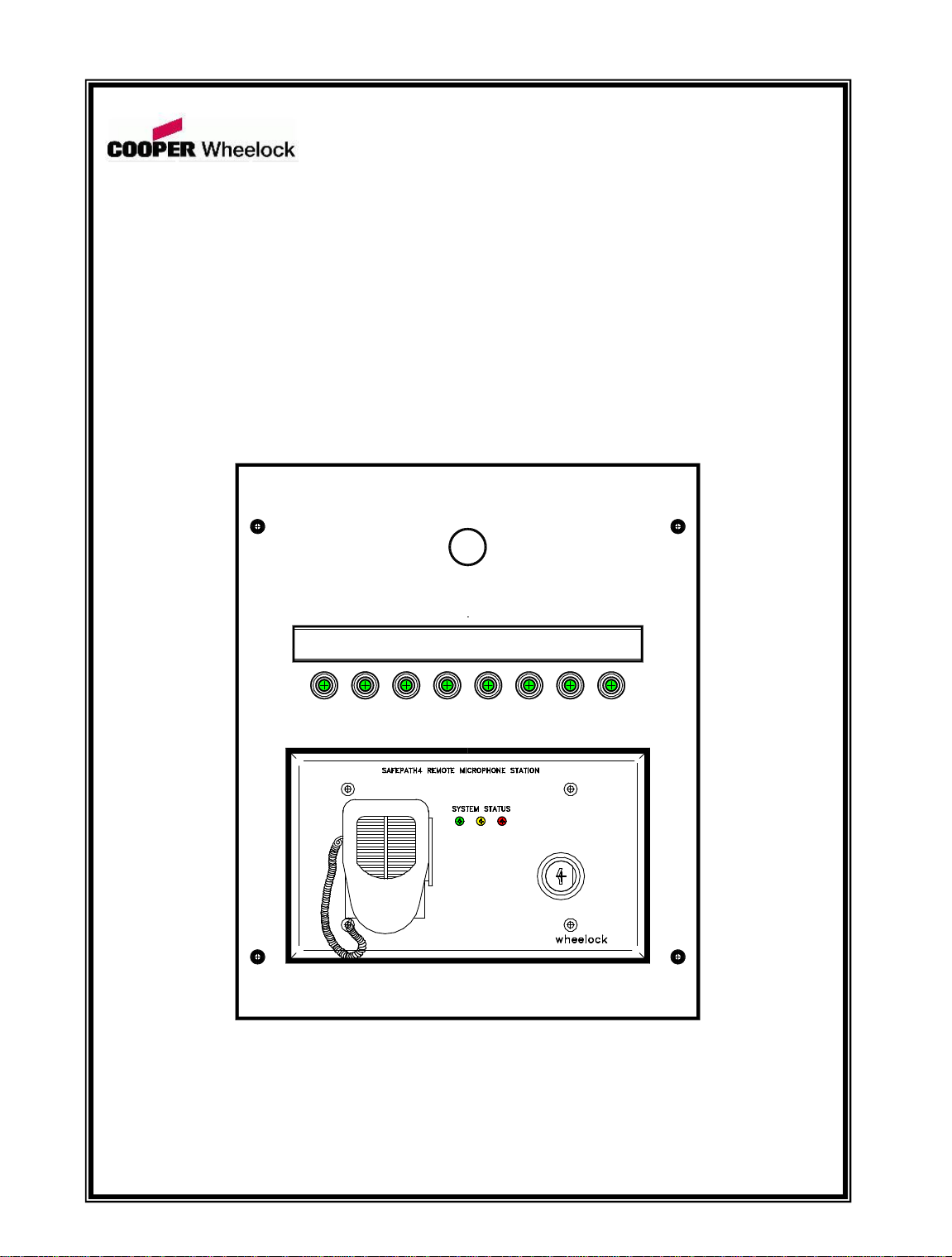
The SP4 –LOC Remote Microphone and Local Operator Console is designed to be used
with the Facility Communications System using the SafePath4 SP40/2 and the SP40S
panels. It contains the SafePath4 SPRM Remote Microphone Module and eight black
Push On /Push Off buttons which provide a contact closure to activate the SP40/2 or the
SP40S digital messages in the Push On position. These buttons change color from black
in the OFF position to green in the ON position. A message name plate holder is located
above the pushbuttons. An optional red mushroom type, cutoff pushbutton is available for
HVAC emergency shutoff.
The Remote Microphone (SPRM) incorporates a Push-To-Talk (PTT) microphone and
system status LED indicators. The SPRM provides a microphone override for any tone
generation, digital voice module prerecorded message, background music, or telephone
paging. It is equipped with a keyed lock that, when activated allows the use of the
module. The key can not be removable in the ON position. The SPRM is fully supervised
from the SP40/2 or SP40S panel and contains front panel LED’s for remote indications of
System Normal, System Trouble and Alarm conditions. Voice frequency response shall
be 275 Hz - -6.5 kHz +/- 2.4 dB. Power requirements shall be 24VDC and will be
supplied by the SP40/2 or SP40S. Input current for standby mode shall be 26mA and
38mA in the alarm mode. Shielded 6-wire cable shall be used. Approvals for the system
shall include; UL Standard 864, UL Standard 1711, FCC Part 15, and CSFM. The panel
shall be OSHA 1910.165 and ADA compliant
The SP4-LOC is available in two models. The flush mount model has a 1/2 inch skirt
around the door section, while the surface mount model door section is flush with the
back box. Both models use the same white 4 inch deep backbox with three 1/2 inch/ 3/4
inch double knockouts, one each in the back center, and top and bottom of the backbox.
The flush mount door section has exterior dimensions of 15-1/2 inches wide and 16-1/4
inches high. The surface mount model has dimensions of 14-1/2 inches wide, 15-1/2
inches high and 4 inches deep. Both models have a pull slam latch to open the continuous
hinged door. Both models are available in white.
The SP4-LOC can be installed up to 2,000 feet from the SP40/2 or SP40S panel using 1418 AWG wiring. Shielded wire is only required for the 1Vrms output from the SPRM.
3
Page 4
Notation Conventions
This manual uses the following notation conventions:
INDICATES A POTENTIALLY HAZARDOUS SITUATION THAT, IF NOT
AVOIDED, COULD RESULT IN SERIOUS PERSONAL INJURY OR DEATH
TO YOU AND OR OTHERS.
Indicates a potentially hazardous situation that, if not avoided, could result in minor or
moderate injury. It may also be used to alert against unsafe practices.
Safety
De-energize all electrical circuits and equipment associated with installing the SP4-LOC.
If the HVAC Pushbutton option is being added, the circuit can contain high voltage that
can cause serious injury or death to the installer.
Additional copies of this manual may be obtained from www.cooperwheelock.com in the
Technical Support section, or from:
Cooper Wheelock, Inc.
273 Branchport Ave.
Long Branch, N.J. 07740
Tel: (732) 222- 6880
Fax: (732) 222- 2588
E-mail: info@cooperwheelock.com
4
Page 5

Technical Specifications
Dimensions (H x W x D)
See Figure 1.
Backbox: 15 1/4 x 14 1/2 x 4 in.
Surface Front: 15 1/4 x 14 1/2 x 1/8 in.
Flush Front: 16 1/4 x 15 1/2 x 1/8 in.
Weight
8 lb.
Finish
White
Mounting
Indoor surface mount
Indoor flush mount
Wiring
Entry
Top, bottom and back knockouts (1/2”
and 3/4”) (3 total)
Door Lock
Pull slam latch with 1/8” security tamper
indicator installation holes
PC Boards
SPRM
Operating Temperature
0 to 49 °C (32 to 120 °F)
Storage Temperature
-20 to 70 °C (-4 to 158 °F)
Humidity, Non-condensing
85±5% at 30±2 °C (86 4 °F)
Pushbutton switch rating
30 VDC at ½ Amp (15 Watts)
HVAC mushroom pushbutton
230VAC at 3 Amps.
SPRM from the SP40S
Maximum distance from SP40S
is 2,000 feet using 14–18 AWG
shielded wire.
6 wire
Input Voltage 24VDC at .038 Amps
1Vrms audio output to SP40S.
Contact closure to SP40S.
Mechanical
Environmental
Electrical
5
Page 6

MASS NOTIFICATION
SYSTEM
15.50"
14.50"
16.25"
15.25"
BACKBOX OUTLINE
TRIM RING 1/2"
PANEL DOOR
Figure 1. Outside Dimensions for the SP4-LOC Front
Mounting
COMPLY WITH ALL OF THE LATEST APPLICABLE CODES, REGULATIONS, LAWS,
STANDARDS, AND GUIDELINES.
1. Remove the FRONT DOOR ASSEMBLY from the backbox by removing the eight (8)
nuts holding the assembly in place.
2. Remove the INNER DOOR ASSEMBLY (Figure 2) and terminal block from the
backbox.
6
Page 7

MASS NOTIFICATION SYSTEM
SAFEPATH4 REMOTE
MICROPHONE (SPRM)
EIGHT (8) PUSH ON/PUSH OFF
BUTTON SWITCHES (WHEN THE
GREEN PUSH SWITCH IS PUSHED
TO THE ON POSITION, THE COLOR
CHANGES TO BLACK.)
MESSAGE NAMEPLATE
HOLDER
MOUNTING HOLE FOR
OPTIONAL HVAC
EMERGENCY CUTOFF
PUSHBUTTON
#8-32 TRUSS HEAD SCREWS FOR
MOUNTING THE INNER DOOR
Figure 2. Inner Door Assembly
2. Mount the backbox assembly. See Figure 3 for mounting holes. Insure that the
orientation label inside the backbox is pointing “UP” and that the studs for mounting
the terminal block are on the left side.
NOTE: All mounting holes are laser cut as knockouts. Punch out the holes required for
either flush or surface mounting.
7
Page 8

14.50"
15.25"
9.25"
11.00"
SURFACE
MOUNT
HOLES (4)
FLUSH
MOUNT
HOLES (8)
1/4"x1/2"
DOUBLE KNOCKOUT (3)
TOP, BOTTOM, AND BACK
1/2"/3/4"
TERMINAL BLOCK
MOUNTING STUDS
#8-32
Figure 3. Mounting Holes for Mounting the Backbox, Flush and Surface
3. Connect conduit fittings to the desired cable knockouts, and run the appropriate
pushbutton and SPRM wiring into the backbox.
If the optional HVAC pushbutton is installed, run the HVAC wiring through a separate
conduit away from the push button and remote microphone wiring. This will prevent
electrical interference and false troubles from appearing on the SP40S.
NOTE: If the SP4-LOC is being flush mounted and finish work on the location has to be
completed, stop here and complete the work before connecting and mounting the
inner and outer doors.
8
Page 9

Installing and Wiring the Inner Door
MASS NOTIFICATION SYSTEM
_
_
+
_
+
+
TB7
IN1
IN2
IN3
IN4
_
+
_
+
_
+
IN5
IN6
SP40/2
SP4-3MEM
_
_
+_+
+
TB1
24V
S1 S2 S3 S4 S5 S6 S7 S8
SP4-LOC HARNESS WIRING
S1
S2
S8
S7
S6
S5
S4
S3
4. Place the terminal block with the wire harness pointing down, onto the terminal block
studs.
5. Connect the wire tie around the harness and to the bottom terminal block stud.
6. Using the washers and nuts, fasten the terminal block to the backbox..
7. If applicable, mount and wire the optional HVAC Emergency Shutoff pushbutton.
8. Connect the pushbutton wiring to the terminal block as shown in Figure 4 (SP40/2) and
Figure 5 (SP40S).
Figure 4. Wiring Diagram SP4-LOC to SP40/2
NOTE: The SP40/2 requires a 9 to 31VDC input in order to initiate a digital message.
9
Page 10

MASS NOTIFICATION SYSTEM
S1 S2 S3 S4 S5 S6 S7 S8
SP4-LOC HARNESS WIRING
S1
S2
S8
S7
S6
S5
S4
S3
_
_
+
_
+
+
TB7
_
+
IN1
IN2
IN3
IN4
_
_
+
_
+
+
TB8
_
+
IN5
IN6
IN7
IN8
SP40S
Figure 5. Wiring Diagram SP4-LOC to SP40S
NOTE: The SP40S inputs can be supervised by placing a 10K Ohm resistor across each
pair of input terminals on the SP4-LOC terminal block and by switching ON the
DIP switches on switch block SW7 positions 1 through 8.
9. Connect the SPRM to the SP40. Figure 6 shows the proper wiring connections for the
SPRM to the SP40/2. Figure 7 shows the proper wiring connections for the SPRM to
the SP40S.
10
Page 11

REMOTE MICROPHONE
SP40/2 PANEL
AUDIO OUT
AUX IN
CC/NAC
+
-
+
-
TB6
24VDC
RM AUDIO
STATUS (CC)
-
+
-
+
654321
+
-
+
-
+
+
+
-
-
IN
BAT
24V
Figure 6. Wiring Diagram SPRM to SP40/2
REMOTE MICROPHONE
SP40S PANEL
24V OUT
AUX
CC/NAC
+
-
+
-
TB6
24VDC
RM AUDIO
STATUS (CC)
-
+
-
+
654321
+
-
+
-
This wiring is power limited.
Figure 7. Wiring Diagram SPRM to SP40S
This wiring is power limited.
10. Mount the INNER DOOR to the backbox using the four #8-32 truss head screws and
plastic washers.
11. Mount the FRONT DOOR to the backbox using the eight washers and #8-32 nuts in
the locations shown in Figure 11.
NOTE: Figure 8 shows a diagram of a surface mount FRONT DOOR with a dotted line
indicating the trim ring for a flush mount door.
11
Page 12

MASS NOTIFICATION
SYSTEM
1/8" SECURITY
WIRE HOLES
SLAM LATCH
#8-32 X 3/4" STUDS (8)
ON BACK OF FRONT RING
1/2" TRIM RING ON FLUSH
MOUNT MODEL FRONT RING
Figure 8. Front Door Layout
_
_
+
_
+
+
TB6
AUX
IN
AUX
CC/NAC
AUX IN
NAC
CC
W5
W4
SW4
100V
70V
25V
1V
AUDIO OUT
AUXILIARY INPUT SELECTION
JUMPER J4. SELECT 1V POSITION
CC/NAC SWITCH SW4
PLACE IN CC POSITION
AUXILIARY INPUT SUPERVISION
JUMPER W5. REMOVE FOR
SUPERVISION.
Operating Instructions:
SP40/2 Panel
Figure 9. Switch locations on the SP40/2 for SPRM Operation
12
Page 13

Figure 9 shows the locations of the switches and LED’s on the SP40/2 that are required
_
_
+
_
+
+
TB6
AUX
CC/NAC
24V OUT
CC/NAC
SW6
100V
70V
25V
1V
J4
AUX
IN
AUX
SUP
JP4
SP40S
CC/NAC SWITCH SW6
PLACE IN CC POSITION
AUXILIARY INPUT SELECTION
JUMPER J4. SELECT 1V POSITION
AUXILIARY INPUT SUPERVISION
JUMPER JP4. REMOVE FOR
SUPERVISION.
for SPRM operation.
1. Set the NAC/CC switch (SW4) on the SP40/2 PC board to the CC position.
2. Set the AUX IN jumper J2 to the 1V position.
3. Remove AUX SUP jumper (W5).
4. Install a UL Listed 10K Ohm End of Line Resistor (EOLR) on the AUX IN of
SP40/2.
SP40S Panel
Figure 10. Switch and Jumper locations on the SP40S for SPRM Operation
See Figure 10 for switch and jumper locations.
1. Set the NAC/CC Switch (SW6) on the SP40S PC board to the CC position.
2. Set the AUX IN jumper J4 to the 1V position.
3. Remove AUX SUP jumper (JP4)
Testing
1. Energize the SP40/2 or SP40S Panel. Install the backup batteries.
2. Test each pushbutton circuit to insure the SP4-LOC is operational.
3. Insert key and turned to the ON position for the controls to function. (The key is
removable only in the OFF position.)
13
Page 14

HVAC
SHUTOF F
1
2
1
2
3
5
4
3
MASS NOTIFICATION SYSTEM
4
INNER PANEL
BACK BOX
FRONT DOOR ASSEMBLY
5
6
6
7
7
(SURFACE AND FLUSH)
8
SYSTEM
MASS NOTIFICATION
8
PARTS LEGEND:
ELECTRICAL CONDUIT AND FIELD WIRES.
(1/2" AND 3/4" KNOCKOUTS PROVIDED ON
TOP, BOTTOM AND BACK FACE.)
SP4-LOC BACKBOX
ORIENTATION LABEL
#8-32 TRUSS HEAD (4) INNER PANEL
MOUNTING SCREW
TERMINAL STRIP AND WIRING HARNESS
1/4" DIAMETER HOLE (6) TO ACCEPT #8-32
STUDS FROM FRONT DOOR PANEL. #8-32
SEMS NUT (6) PROVIDED.
OPTIONAL "HVAC SHUTOFF" LABEL AND
MUSHROOM HEAD PUSHBUTTON SWITCH
1/8" HOLES (2) FOR SECURITY TAMPER
INDICATOR
Figure 11. Exploded View of the Sp4-LOC
14
Page 15

Warranty
Limited Warranty
Cooper Wheelock, Inc. products must be used within their published specifications and
must be PROPERLY specified, applied, installed, operated, maintained, and
operationally tested in accordance with these instructions at the time of installation and at
least twice a year or more often in accordance with local, state and federal codes,
regulations and laws. Specification, application, installation, operation, maintenance, and
testing must be performed by qualified personnel for proper operation in accordance with
all of the latest National Fire Protection Association (NFPA), Underwriters' Laboratories
(UL), Underwriters’ Laboratories of Canada (ULC), National Electrical Code (NEC),
Occupational Safety and Health Administration (OSHA), local, state, county, province,
district, federal and other applicable building and fire standards, guidelines, regulations,
laws and codes including, but not limited to, all appendices and amendments and the
requirements of the local authority having jurisdiction (AHJ). Cooper Wheelock, Inc.
products when properly specified, applied, installed, operated, maintained, and
operationally tested as provided above are warranted against mechanical and electrical
defects for a period of three years from date of manufacture (as determined by date code).
Correction of defects by Cooper Wheelock, Inc providing repairs or a replacement shall
be at Cooper Wheelock, Inc.'s sole discretion and shall constitute fulfillment of all
warranty obligations.
The foregoing limited warranty shall immediately terminate in the event any part not
furnished by Cooper Wheelock, Inc. is installed in the product. The foregoing limited
warranty specifically excludes any software required for the operation of or included in a
product. COOPER WHEELOCK, INC. MAKES NO REPRESENTATION OR
WARRANTY OF ANY OTHER KIND, EXPRESS, IMPLIED OR STATUTORY
WHETHER AS TO MERCHANTABILITY, FITNESS FOR A PARTICULAR
PURPOSE OR ANY OTHER MATTER.
Users are solely responsible for determining whether a product is suitable for the user's
purposes, or whether it will achieve the user's intended results. There is no warranty
against damage resulting from misapplication, improper specification, abuse, accident, or
other operating conditions beyond Cooper Wheelock, Inc.'s control.
Some Cooper Wheelock, Inc. products contain software. With respect to those products,
Cooper Wheelock, Inc. does not warranty that the operation of the software will be
uninterrupted or error-free or that the software will meet any other standard of
performance, or that the functions or performance of the software will meet the user's
requirements. Cooper Wheelock, Inc. shall not be liable for any delays, breakdowns,
interruptions, loss, destruction, alteration, or other problems in the use of a product
arising out of or caused by the software.
The liability of Cooper Wheelock, Inc. arising out of the supplying of a product, or its
use, whether based on warranty, negligence, or otherwise, shall not in any case exceed
the cost of correcting defects as stated in the limited warranty and upon expiration of the
warranty period all such liability shall terminate. Cooper Wheelock, Inc. is not liable for
labor costs incurred in removal, reinstallation, or for damage of any type whatsoever,
including but not limited to, loss of profit or incidental or consequential damages. The
15
Page 16

foregoing shall constitute the sole remedy of the purchaser and the exclusive liability of
Cooper Wheelock, Inc.
In no case will Cooper Wheelock, Inc.'s liability exceed the purchase price paid for a
product.
Limitation of Liability
Cooper Wheelock, Inc.'s liability on any claim of any kind, including negligence, breach
of warranty, or otherwise, for any loss or damage resulting from, arising out of, or
connected with any contract, or from the manufacture, sale, delivery, resale, repair or use
of any product shall be limited to the price applicable to the product or part thereof which
gives rise to the claim. Cooper Wheelock, Inc.'s liability on any claim of any kind shall
cease immediately upon the installation in the product of any part not furnished by
Cooper Wheelock, Inc. In no event shall Cooper Wheelock, Inc. be liable for any claim
of any kind unless it is proven that our product was a direct cause of such claim.
FURTHER, IN NO EVENT, INCLUDING IN THE CASE OF A CLAIM OF
NEGLIGENCE, SHALL COOPER WHEELOCK, INC. BE LIABLE FOR
INCIDENTAL, INDIRECT, SPECIAL OR CONSEQUENTIAL DAMAGES. Some
states do not allow the exclusion or limitation of incidental or consequential damages, so
the preceding limitation may not apply to all purchasers.
16
 Loading...