

Page 1
Fast-Track Set-up Guide for
SAFEPATH4 SP40S/SP40SE Panel
This guide has been created to provide you with a fast track setup to get your SP40S or SP40SE panel up and
running using the digital voice messaging and live voice modes of operation. Other modes, which include night
ring, telephone paging and background music and other features, are discussed in the technical manual. This guide
is not to take the place of the Installation, Testing, Operation and Maintenance Manual, which you received in this
package. When in doubt, refer to the Manual for additional information. Always Obey All Safety Precautions
and Warnings.
1. Inventory
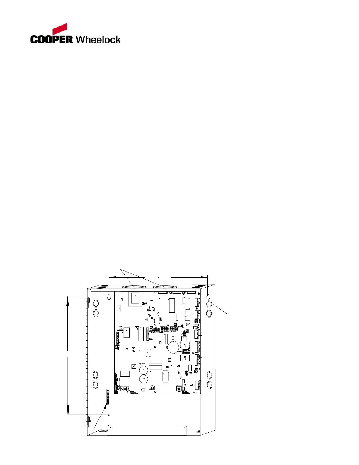
2. Mounting
MAKE SURE THAT ALL EXTERNAL WIRING IS REMOVED, AND ALL ELECTRICAL
COMPONENTS ARE CLEAR BEFORE DRILLING MOUNTING HOLES AND MOUNTING THE
SP40S/SP40SE PANEL.
1. Open the front cover and dead front panel.
2. Mount the Panel in the desired location-using Figure 1 for hole configuration.
When you receive your new Panel, check to see that you have the following items:
• SP40S or SP40SE Panel.
• Package of test EOLRs (End of Line Resistors)
• Operation and Installation Manual
• 2 UL Listed 10K Ohm EOLRs.
• Hardware Kit containing Battery connection wires
2" - 2 1/2" - 3" Conduit
Knockouts (2 Places)
14.00"
TB
AU
24
SP
3/4" - 1" Conduit
Knockouts (18 Places)
AU
CC/
24V
17.00"
Grounding
Terminal
Block
Figure 1
1
Page 2
3. Connect conduit fittings and conduit to the Panel through the conduit entrances shown on Figure 1 as
necessary. Wire the Power input on the left bottom of the Panel, and input and output wiring on the right
side of the Panel.
4. Install field wiring in conduit as required.
5. Connect the Panel to earth ground at grounding stud shown on Figure 1.
6. Make sure that all debris is cleared from the enclosure.
7. For more details refer to Chapter 3 of the SP40S or SP40SE Installation, Testing, Operation and Maintenance
Manual.
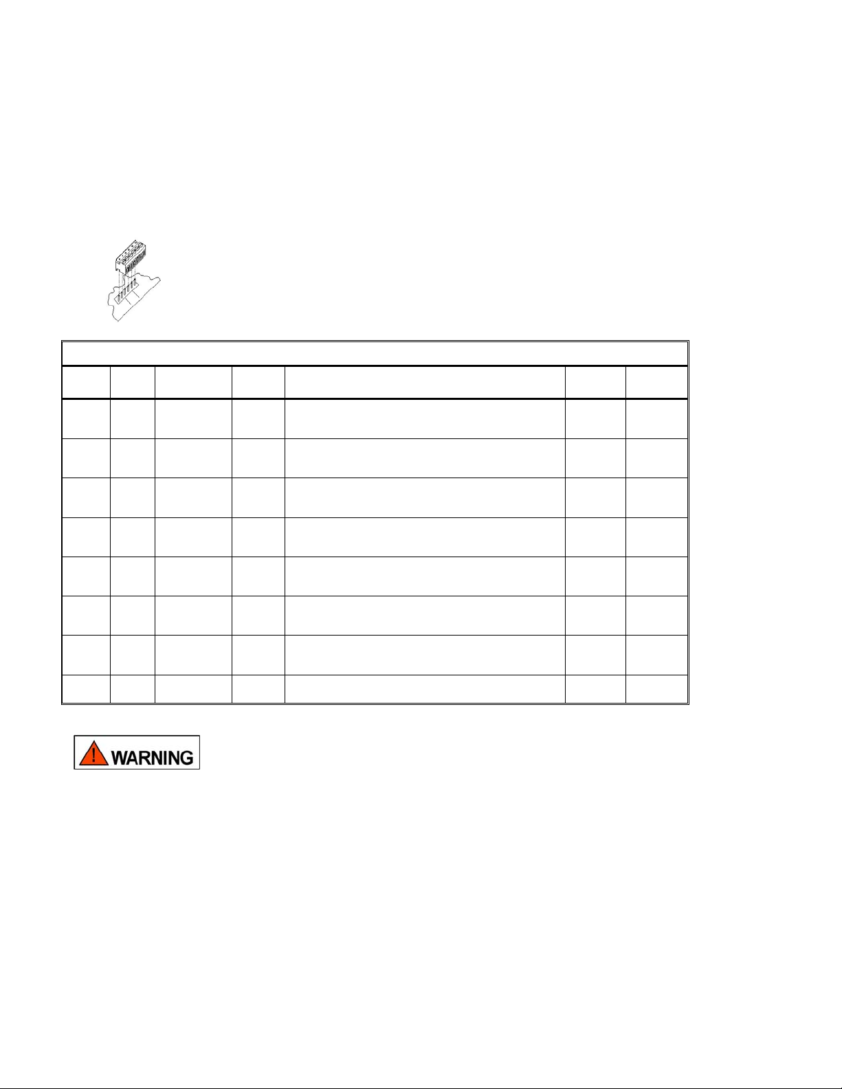
3. Wiring
The terminal blocks on the SP40S/E are removable. Lift the terminal block from the circuit
board, attach wires to the desired connections, and then plug the terminal block back on
the board.
Table 1 Standard Messages for the SP40S/SP40SE
Message # Priority # `Type of
IN1
IN2 4 Fire (do not use
IN3 5 Fire Male “May I have your attention please! A fire emergency has been
IN4 6 Emergency Female “May I have your attention please! An emergency has been reported
IN5 7 Emergency Male “May I have your attention please! An emergency has been reported
IN6 8 Weather Male “May I have your attention please! The National Weather Service
IN7 9 All Clear Male “May I have your attention please! The building emergency has
IN8 10 Test Male “May I have your attention please! This is a test of the Cooper
3 Fire (do not use
Message
elevators)
elevators)
Voice
Type
Male “May I have your attention please! A fire emergency has been
Female “May I have your attention please! A fire emergency has been
Message Script
reported in the building. While this is being verified, please leave
the building by the nearest exit. Do not use the elevators.”
reported in the building. While this is being verified, please leave
the building by the nearest exit. Do not use the elevators.”
reported in the building. While this is being verified, please leave
the building by the nearest exit.”
in the building. While this is being verified, please leave the
building and report to the designated assembly are for your group.”
in the building. While this is being verified, please leave the
building and report to the designated assembly are for your group.”
has issued a severe weather warning for our area.”
ended. An all clear has been given. Please resume normal activities.”
Wheelock evacuation system, repeat, this is only a test.”
Pre-Tone Post Tone
Three (3)
rounds of
code 3 tone
Three (3)
rounds of
code 3 tone
Three (3)
rounds of
code 3 tone
Three (3)
rounds of
code 3 tone
Three (3)
rounds of
code 3 tone
Eight (8)
seconds of
1KHz tone
Eight (8)
seconds of
1KHz tone
No Tone No Tone
Three (3)
rounds of
code 3 tone
Three (3)
rounds of
code 3 tone
Three (3)
rounds of
code 3 tone
Three (3)
rounds of
code 3 tone
Three (3)
rounds of
code 3 tone
Eight (8)
seconds of
1KHz tone
Eight (8)
seconds of
1KHz tone
ALWAYS APPLY AC POWER BEFORE CONNECTING BATTERY BACKUP. ALWAYS
DISCONNECT BATTERY BACKUP BEFORE DISCONNECTING AC POWER.
IMPROPER CONNECTIONS CAN CAUSE DAMAGE TO THE EQUIPMENT AND
PERSONAL INJURY.
2
Page 3

Connect the wiring to the proper terminals in the order shown in Figure 2.. Table 1 shows the factory installed
messages for each of the inputs (IN1 through IN8)
ALM
NONCC NONCC
TB1
DV
1
1
TB2
SW3
4 5 6 7
2 3
4 5
2 3
STROBE ACTIVATION
SW3
NONCC NONCC
9-MIC
10-AUX
10
8 9
6 7
8 9 10
TRB
NO NC C
SW7
6 7 8 9
1
4 5
2 3
IN CC
ON
SUPERVISION
1
4 5 6 7
2 3
SW7
SP40S/E
AC TRB
NONCC
TB3
TB4
AUD OUT
24V OUT
SPB SUP
TB5
NR
TEL
BGM
MIC
J3
TB6
AUX
CC/NAC
24V OUT
TB7
IN1
IN2
AUX TO
10
10
8 9
TB10
BAT
IN3
IN4
TB8
IN5
IN6
IN7
IN8
TB12
STB OUT
RET
STB IN
1. WIRE THE SPEAKER CIRCUIT
TO THE AUD OUT TERMINALS.
25/70VRMS @ 40 WATTS AUDIO OUT
REQUIRES A UL LISTED 10K OHM
EOLR AT END OF CIRCUIT
(THE OUTP U T VOLTAGE IS F ACTO R Y
SET AT 70VRMS. CHANGING THE
VOLTAGE TO 25VRMS IS DESCRIBED
IN CHAPTER 4 OF THE MANUAL.)
AUX TO
10
IN CC
SUPERVISION
SW7
ON
1
2 3
1
2 3
4 5 6 7
6 7
4 5
8 9
8
10
9
2. WIRE THE DIGITAL VOICE MESSAGE
INIT IATIN G CIR CUIT ( S) TO IN1 THRU
IN8 AS D ESIR E D.
INPUTS 1 THRU 8 REQUIRES CONTACT
CLOSURE. SUPERVISE THE INPUTS BY
PLACING A UL LISTED 10K OHM EOLR AT
THE CONTACT CLOSURE SOURCE AND
TURN ON THE CORRESPONDING
MESSAGE SWITCH ON DIP SWITCH
BLOCK SW7.
DV
1
4 5
2 3
1
4 5
2 3
STROBE ACTIVATION
SW3
6 7
6
7 8
8
9-MIC
10-AUX
10
9
9
10
3. WIRE THE STROBE CIRCUIT TO THE
STB OUT TERMINALS.
24VDC @ 2AMPS STROBE OUT REQUIRES
A UL LISTED 10K OHM EOLR AT END OF
CIRCUIT. IF STROBE CIRCUIT IS NOT USED
TURN OFF CORRESPONDING MESSAGE DIP
SWITCH ON DIP SWITCH BLOCK SW3
BLACK WHITE
GREEN
115VAC AT 2.15 AMPS/230VAC AT 1.4 AMPS
4. CO ECT THE AC WIRES
NN
TO THE INPUT TERMINALS.
TURN ON THE AC CIRCUIT.
5. CONNECT THE BA TTER
TO THE BACKUP BATTE
BATTERY CONNECTION 24VDC @ 7 TO 33
AMPHOURS. BATTERIES LARGER THAN
12 AMPHOURS REQUIRE AN EXTERNAL
BATTERY BOX (BATC).
WIRING KIT CONTAINS A BLA RED
WIRE USED TO ATTACH THE TTERIES TO
THE BATTERY TERMINALS. IT LSO CONTAINS
A YELLOW WIRE USED TO CO NECT THE TWO
BATTERIES TOGETHER IN SE ES.
Y TERMINALS
RIES
CK AND A
BA
A
N
RI
YELLOW BATTERY WIRE
_
+
E
T
T
A
B
C
D
V
2
1
+
_
T
T
A
B
C
D
V
2
1
Y
R
Figure 2
Y
R
E
3
Page 4

4. Checkout
The following is the checkout procedure to insure proper operation. If any steps in the checkout procedure produce
a yellow SYSTEM TROUBLE or AC TROUBLE LED on the keypad (See Figure 3), and an audible tone on the
SP40S circuit board, refer to Chapter 8 “Troubleshooting” in the Installation, Testing, Operation and Maintenance
Manual. To turn off the tone, momentarily depress the “Trouble Silence” pushbutton on the keypad.
POWER ON
TROUBLE
SILENCE
RECORD
SYSTEM
TROUBLE
MESSAGES
AC
TROUBLE
ALARM
ACTIVE
Fire (Do not use elevators)
Male Voice
Fire (Do not use elevators)
Female Voice
Fire
Male Voice
Emergency
Female Voice
Emergency
Male Voice
Weather
Male Voice
All Clear
Male Voice
Test
Male Voice
Figure 3
STROBE
ACTIVE
1. Using the push on / push off buttons
on the keypad, push on the button that
corresponds to the message(s) selected
on the PC board. Push off the button to
stop the message.
2. Test the microphone circuit by
removing the microphone from its
holder and speaking into it while
depressing the push to talk button.
(For best results hold the microphone
within one-half inch from your mouth.)
3. Initiate each selected digital message
at the remote source, such as the
FACP, and verify operation.
4. Close the dead front panel and
close the front cover.
5. Congratulations
Congratulations! You have now completed the basic installation of the SP40S or SP40SE Panel. We trust it will
give you years of trouble free operation. Should a problem arise, refer to your Installation, Testing, Operation and
Maintenance Manual. If problems persist, contact the Technical Support Engineering Department at Cooper
Wheelock Inc. (800) 631-2148.
Copyright 2007 Cooper Wheelock Inc. All rights reserved. P84743 B
273 Branchport Avenue,
Long Branch, NJ 07740-6899
Ph: (800) 631-2148
Fax: (732) 222-2588
www.cooperwheelock.com
E-Mail:
info@cooperwheelock.com
4
 Loading...