

Page 1
AC
TB7
L
N
F2
TB1
+
IN
_
_
+
BAT
24V
_
+
W1
AC
BAT
D37
D11
AC
GRN
SAFEPATH4
F1
SW2
SP40/2
U8
RECORD
D34
D22
D36
ON
D35
4
2 3
1
D9
DV
MIC
AMP
W2
D10
STB
SHORT
P/N 108985
SW1
D39
SW3
D13
STB
OPEN
ON
TBL
YEL
1
1
2
2 3
P/N 109928
MIC1
W8
W3
BGM
STB
RED
D14
R
3
4
TEL
Installation, Testing,
CC
W5
W4
D58
D54
AUDIO
OPEN
SW4
AUDIO
SHORT
D49
D60
TONE
AUX
IN
GF
E-Mail: info@wheelockinc.com
Assembly A84162-001 Rev. D
Part Number P84116 Rev. J
AUX
DV
1V
J2
25V
70V
100V
NAC
Operation, and Maintenance
W7
Manual
273 Branchport Avenue, Long Branch, NJ 07740-6899 Ph: (732) 222-6880 Fax: (732) 222-2588
Toll Free 800-631-2148 Web Site: www.wheelockinc.com
P84014 REV
100V
70V
J4
25V
J3
STB OUT
TB2
TB3
TB4
TEL
BGM
TB5
AUDIO OUT
CC/NAC
AUX IN
TB6
W6
E1
RET
STB IN
A
NO
L
NC
M
COM
NO
T
NC
R
B
COM
IN3
IN2
IN1
NR
+
_
+
_
+
_
+
_
+
_
+
_
+
_
+
_
+
_
+
_
+
_
+
_
Page 2

Intentionally Blank
ii
Page 3

Typographical Notation Conventions
Thank you for using our products. Use this product according to this instruction manual. Please
keep this instruction manual for future reference.
ANY MATERIAL EXTRAPOLATED FROM THIS DOCUMENT OR FROM WHEELOCK
MANUALS OR OTHER DOCUMENTS DESCRIBING THE PRODUCT FOR USE IN
PROMOTIONAL OR ADVERTISING CLAIMS, OR FOR ANY OTHER USE, INCLUDING
DESCRIPTION OF THE PRODUCT'S APPLICATION, OPERATION, INSTALLATION AND
TESTING IS USED AT THE SOLE RISK OF THE USER AND WHEELOCK WILL NOT HAVE
ANY LIABILITY FOR SUCH USE.
Certain information contained in this manual has been extracted from the NFPA 72 Manual (1999
Edition) and the Life Safety Code 101™ Manual (2000 Edition).
Notation Conventions
This manual uses the following notation conventions:
WARNING: INDICATES A POTENTIALLY HAZARDOUS SITUATION THAT, IF NOT
AVOIDED, COULD RESULT IN PROPERTY DAMAGE AND SERIOUS PERSONAL INJURY
OR DEATH TO YOU AND OR OTHERS.
CAUTION: Indicates a potentially hazardous situation that, if not avoided, could result in
minor or moderate injury. It may also be used to alert against unsafe practices.
Part Number: P84116 Rev. J
Copyright 2005 Wheelock, Inc. All rights reserved.
iii
Page 4

Intentionally Blank
iv
Page 5

Table of Contents
Typographical Notation Conventions…………………………………………………………… iii
Table of Contents…………………………………………………………………………………. v
Table of Figures…………………………………………………………………………………… vii
Table of Tables……………………………………………………………………………………. viii
Chapter 1 – Safety Precautions…………………………………………………………………. 1-1
Section 1-1 – Read This Manual…………………………………………………………. 1-1
Section 1-2 – Operational Safety………………………………………………………… 1-1
Section 1-3 – Compliance with Applicable Codes, Regulations, Laws, Standards,
And Guidelines……………………………………………………………. 1-2
Section 1-4 – Property Insurance Recommendation………………………………….. 1-2
Section 1-5 – Audio Output Considerations……………………………………………. 1-2
Section 1-6 – RF Interference…………………………………………………………… 1-3
Section 1-7 – General…………………………………………………………………….. 1-3
Chapter 2 – Overview and Features……………………………………………………………. 2-1
Section 2-1 - Description…………………………………………………………………. 2-1
Section 2-2 – Enclosure and Configuration…………………………………………….. 2-3
Section 2-3 – Nominal Electrical Data………………………………………………….. 2-3
Section 2-4 – Operation Modes…………………………………………………………. 2-4
Chapter 3 – Installation and Setup……………………………………………………………… 3-1
Section 3-1 – Introduction………………………………………………………………… 3-1
Section 3-2 – Fire Alarm Control Panel Wiring Applications…………………………. 3-1
Section 3-3 – General Installation Instructions………………………………………… 3-1
See warning concerning BGM source on page 3-7.
Section 3-5 – Mounting…………………………………………………………………… 3-14
Section 3-6 – System Checkout…………………………………………………………. 3-16
Section 3-7 – Ground Fault Detection Sensitivity Adjustment……………………….. 3-20
Section 3-8 – Battery Care and Backup Battery Calculations………………………... 3-20
Section 3-9 – AC Power and Battery Installation Procedures…………………...…… 3-21
Chapter 4 – Operation…………………………………………………………………………… 4-1
Section 4-1 – Introduction……………………………………………………………….. 4-1
Section 4-2 – Operator’s Console………………………………………………………. 4-1
Section 4-3 – Supervision……………………………………………………………….. 4-1
Section 4-4 – Actions That Initiate Alarms…………………………………………….. 4-2
Chapter 5 – Operational Procedures………………………………………………………….. 5-1
Section 5-1 – Operator Instructions……………………………………………………… 5-1
Section 5-2 – To Make Live Announcements………………………………………….. 5-1
Section 5-3 – To Record Digital Voice Messages……………………………………… 5-1
v
Page 6

Chapter 6 – Periodic Testing and Maintenance………………………………………………. 6-1
Section 6-1 – Introduction………………………………………………………………… 6-1
Section 6-2 – Periodic Testing…………………………………………………………… 6-1
Section 6-3 – Faulty Equipment…………………………………………………………. 6-1
Section 6-4 – Qualified Personnel………………………………………………………. 6-1
Section 6-5 – Miscellaneous Hardware Testing………………………………………. 6-1
Chapter 7 – Troubleshooting……………………………………………………………………. 7-1
Section 7-1 Introduction………………………………………………….………………. 7-1
Section 7-2 Troubleshooting………………………………….……………..…………… 7-1
Section 7-3 SP40/2 Panel Wiring Diagram……………….……………………………. 7-7
Chapter 8 – Technical Data…………………………………………………………………….. 8-1
Section 8-1 – Mechanical……………………………………………………………….. 8-1
Section 8-2 – Environmental……………………………………………………………. 8-1
Section 8-3 – Electrical………………………………………………………………….. 8-1
Chapter 9 – Module Descriptions…………………………………………………….………… 9-1
Section 9-1 – Introduction………………………………………………..………………. 9-1
Section 9-2 SP40/2 Motherboard ……………………….………………………………. 9-3
Chapter 10 – Warranty……………………………………….………………………………….. 10-1
Battery Backup Calculation Sheet……………………………………….……………………… 11
vi
Page 7

List of Figures
Figure 2-1 Basic Capabilities of the SP40/2 Panel………………………………………….……..… 2-4
Figure 2-2 Layout of a SP40/2 Panel…………………………………………………………… 2-5
Figure 3-1 Location of Wire Connections………………………………………………………. 3-2
Figure 3-2 Removable Terminal Block………………………………………………………….. 3-4
Figure 3-3 Strobe Input and Output Connections……….…………………………………… 3-5
Figure 3-4 Audio Output Connections…………………………………………………………. 3-5
Figure 3-5 Digital Voice Initiating Connections………….……………………………………… 3-6
Figure 3-6 Ancillary Audio Input Connections…………………………………………………. 3-7
Figure 3-7 Alarm and Trouble Connections………………………….………………………… 3-8
Figure 3-8 Wiring Diagram for Visual Only Notification Appliances………………………... 3-11
Figure 3-9 Wiring Diagram for Combination Audio/Visual Notification Appliances………… 3-11
Figure 3-10 Wiring Diagram for Audio Only Notification Appliances………………………… 3-11
Figure 3-11 Alarm Relay Contacts……….……………………………………………………… 3-13
Figure 3-12 Trouble Status Relay Contacts……………….……………………………………. 3-13
Figure 3-13 Input Power and Battery Connection Locations……………….…………………. 3-14
Figure 3-14 SP40/2 Panel Mounting and Grounding Location.………..………….………… 3-15
Figure 3-15 Jumper/Switch/Variable Resistor Location……….……………………………. 3-16
Figure 3-16 120VAC Input connection……………………………………….………………… 3-22
Figure 3-17 Battery Wire Connections…………………………………………………………. 3-23
Figure 3-18 Battery Alignment and Jumper Connection………………………………..……. 3-24
Figure 5-1 Digital Voice Section…………………………………………………………………. 5-3
Figure 5-2 SP40/2 Panel Operator Console………………..…….……………………………. 5-4
Figure 7-1 Trouble LED and Fuse Locations………………….…………………………….… 7-2
Figure 7-2 SP40/2 Panel Wiring Diagram….………………………………………………….. 7-8
Figure 9-1 SP40/2 Motherboard………………………………………………………………… 9-2
vii
Page 8

LIST OF TABLES
Table 3-1 Terminal Connection Definitions……………………………………………………. 3-3
Table 3-2 Jumper/Switch/Variable Resistor Functions…………….……………………… 3-17
Table 3-3 Digital Voice Message Tests………………………………………………………… 3-19
Table 4-1 Alarm Conditions and Results……………………………………………………….. 4-2
Table 6-1 Miscellaneous Hardware Tests………………………………………..……………. 6-2
Table 7-1 Trouble LED Procedure Cross Reference…………………………………………. 7-3
Table 8-1 Input Activation……………………………………………………………………….. 8-2
Table 8-2 Outputs…………………………………………………………………………………. 8-2
viii
Page 9

Chapter 1 - Safety Precautions
Section 1-1 - Read This Manual
Personnel properly qualified in the application and use of life safety equipment ("qualified personnel") shall
read this manual carefully before performing any actions to specify, apply, install, maintain and
operationally test SP40/2 products in accordance with the instructions in this manual.
This manual shall be kept with the SP40/2 panel for reference during the life of the system. This manual
shall be made available to all qualified personnel who operate, test, maintain, or service SP40/2 products.
It is strongly recommend that such personnel read and understand the entire manual.
Section 1-2 - Operational Safety
WARNING: IF SAFETY PRECAUTIONS, INSTALLATION AND TESTING INSTRUCTIONS ARE
NOT PERFORMED PROPERLY, THE SP40/2 PANEL MAY NOT OPERATE IN AN EMERGENCY
SITUATION WHICH COULD RESULT IN PROPERTY DAMAGE AND SERIOUS INJURY OR DEATH TO
YOU AND/OR OTHERS.
WARNING: IF THE PROTECTIVE SIGNALING SYSTEM SOUNDS AND/OR FLASHES, IT IS A
WARNING THAT A POSSIBLE SERIOUS SITUATION REQUIRES IMMEDIATE ATTENTION.
CAUTION: SP40/2 printed circuit boards are sensitive to static electricity and have delicate
components mounted on it. Discharge any static electricity from your body by touching a grounded object,
such as a metal screw, which is connected to earth ground. Handle the board by its edges and be careful
not to twist or flex it. The SP40/2 panel is to be installed in a static free area, and the user is to properly
attach grounded wrist straps before touching any static sensitive areas. After handling SP40/2 printed
circuit board, the panel should be tested in accordance with Section 3-5 “System Checkout” of this manual
to verify that it is functioning properly.
NOTE:
In areas prone to lighting strikes, using a surge protection device is recommended. Reference
TESAN number S002-99 for recommended manufacturers of surge protection equipment.
This TESAN (Technical Engineering Support Application Notice) is available from the Wheelock website,
www.wheelockinc.com , and is found under the Technical Support tab.
This SP40/2 panel will not work without power. The SP40/2 panel is powered by 120VAC. 24VDC rechargeable batteries provide back-up power. If both sources of power are cut off for any reason, the
SP40/2 panel will not operate.
DO NOT assume any installation, operation and testing details not shown in this manual.
The SP40/2 panel shall only be operated with the dead front panel properly in place.
Notification equipment cannot last forever. Even though SP40/2 is expected to last up to ten years,
any of its parts or components could fail before then. Therefore testing of the entire protective
signaling system, including the SP40/2
panel, all notification equipment, as well as all messages and
their output channel, and priority assignment, shall be conducted at least twice each year, or more
often as required by local, state and federal codes, regulations and laws, by qualified personnel. If
the notification equipment is not working properly, immediately contact the installer and have all/any
problems corrected immediately. Malfunctioning components should be replaced immediately. Do
not attempt to repair malfunctioning components. Malfunctioning components should be returned for
factory repair or replacement. In the event you cannot contact the installer, contact the manufacturer.
1-1
Page 10

WARNING: FOR PROPER OPERATION IN LIFE SAFETY APPLICATIONS, THE SP40/2
PANEL SHALL BE CONNECTED TO A LISTED COMPATIBLE AND PROPERLY OPERATING
CONTROL PANEL, WHICH CONTROLS ITS ACTIVATION. ALL EQUIPMENT SHALL BE
PROPERLY INTERCONNECTED AND OPERATING. THE INSTALLER SHALL CHECK
COMPATIBILITY OF ALL EQUIPMENT PRIOR TO INSTALLATION, OTHERWISE THE SP40/2
PANEL AND/OR THE CONTROL PANEL MAY BE DAMAGED AND/OR FAIL TO OPERATE IN AN
EMERGENCY SITUATION.
WARNING: CERTAIN HARDWARE FUNCTIONS ON THE SP40/2 PANEL ARE NOT
SUPERVISED. IF ANY SUCH HARDWARE FUNCTIONS FAIL, THE SP40/2 PANEL MAY NOT
PROVIDE THE INTENDED WARNING AND/OR NOT INDICATE A TROUBLE CONDITION.
Section 1-3 - Compliance with Applicable Codes, Regulations,
Laws, Standards, and Guidelines
COMPLY WITH ALL OF THE LATEST APPLICABLE CODES, REGULATIONS, LAWS,
STANDARDS, AND GUIDELINES.
WARNING: FOR EMERGENCY, LIFE SAFETY, AND FIRE PROTECTIVE SIGNALING, SYSTEM
APPLICATIONS USING THE SP40/2, INSTALLATION, TESTING AND MAINTENANCE SHALL BE
PERFORMED BY QUALIFIED PERSONNEL IN ACCORDANCE WITH ALL THE LATEST NATIONAL
FIRE PROTECTION ASSOCIATION (NFPA), UNDERWRITER’S LABORATORY (UL), NATIONAL
ELECTRIC CODE (NEC), OCCUPATIONAL SAFETY AND HEALTH ADMINISTRATION (OSHA),
STATE, COUNTY, LOCAL, PROVINCE, DISTRICT, FEDERAL, AND OTHER APPLICABLE BUILDING
AND FIRE STANDARDS, GUIDELINES, REGULATIONS, LAWS, AND CODES INCLUDING, BUT NOT
LIMITED TO, ALL APPENDICES AND AMENDMENTS AND REQUIREMENTS OF THE LOCAL
AUTHORITY HAVING JURISDICTION (AHJ).
It is recommended that the local AHJ inspect and approve the proposed placement of all the
notification appliances.
NOTE: WHEN INSTALLED IN NYC, THE BACKGROUND MUSIC FEATURE IS NOT PERMISSIBLE.
NOTE: WHEN INSTALLED IN NYC, THE TELEPHONE PAGING FEATURE IS NOT PERMISSIBLE
Section 1-4 - Property Insurance Recommendation
The SP40/2 panel is not a substitute for insurance. All users should have adequate levels of life and
property insurance
.
Section 1-5 - Audio Output Considerations
WARNING: AUDIBLE SIGNALS MAY MASK MEDICAL EQUIPMENT MONITORING ALARMS.
WHERE MEDICAL EQUIPMENT MONITORING ALARMS ARE IN USE, DO NOT USE AUDIBLE
SIGNALS; PROVIDE VISUAL NOTIFICATION APPLIANCES IN HIGHLY VISIBLE LOCATIONS.
1-2
Page 11

CAUTION: The output of the audio system may not be heard in all cases. Sound can be blocked
or reduced by walls, doors, carpeting, wall coverings, furniture, insulation, bed coverings, and other
obstacles that may temporarily or permanently impede the output of the audio system. Sound is also
reduced by distance and masked by background noise. The output of the audio system may not be
sufficient to alert all occupants, especially those who are asleep, those who are hearing-impaired,
those who are wearing devices that plug or cover the ears, and those who have recently used drugs
or alcohol. The output of the audio system may not be heard by an alert person if the output device is
placed in an area which is isolated by a closed door, or is located on a different floor from the person
in a hazardous situation or is placed too far away to be heard over ambient noise such as, but not
limited to, running water, traffic, air conditioners, machinery or musical appliances
If live microphone announcements, audible tones and/or voice messages cannot be readily heard and
understood clearly within the protected areas as intended, it will be necessary to increase the number
and/or sound output intensity of speakers within those areas so that they are heard and understood
clearly when activated
.
.
Section 1-6 - RF Interference
The SP40/2 panel has been tested and found to comply with the limits for a Class A digital device,
pursuant to Part 15 of the FCC Rules. These limits are designed to provide reasonable protection
against harmful interference when the equipment is operated in a commercial environment. This
equipment generates, uses, and can radiate radio frequency energy and, if not installed and used in
accordance with the instruction manual, may cause harmful interference to radio communications.
Operation of this equipment in a residential area is likely to cause harmful interference in which case
the user will be required to correct the interference at his own expense.
Section 1-7 - General
Each manufacturer's fire alarm control panel and notification appliances operate differently and have
different features. Before specifying, installing, operating, testing, maintaining or servicing a system,
carefully read the installation, operation and testing manual for each piece of equipment and
applicable codes.
Additional copies of this manual may be obtained from:
Wheelock, Inc.
273 Branchport Ave.
Long Branch, N.J. 07740
Tel: (732) 222- 6880
Fax: (732) 222- 2588
E-mail: info@wheelockinc.com
1-3
Page 12

Intentionally Blank
1-4
Page 13

Chapter 2 - Overview and Features
Section 2-1- Description
General
The SP40/2 panel is a stand alone, single channel, 40 watt, supervised voice evacuation/emergency
message system with additional features of a Telephone Page Input, Night Ring Input and Background
Music Input. Figure 2-1 illustrates the basic capabilities.
The control panel that activates the SP40/2 panel must provide a Notification Appliance Circuit with a
voltage ranging from 9 to 31VDC.
The SP40/2 panel does
system that does sense such conditions. The SP40/2 panel, when activated, provides a pre-recorded voice
message(s) to speaker notification appliances. When used as part of a protective signaling system, the
SP40/2 panel must be properly connected to a compatible control panel that has been approved by a
nationally recognized testing laboratory ("LISTED") and to LISTED compatible notification appliances for
proper operation.
THE SP40/2 PANEL MUST BE PROPERLY INSTALLED, PROGRAMMED, AND CONNECTED TO A
COMPATIBLE FIRE ALARM CONTROL PANEL TO FUNCTION IN A VOICE EVACUATION SYSTEM.
not sense an emergency condition or hazards such as fire; it is only a part of a
WHEELOCK EXPRESSLY DISCLAIMS ALL LIABILITY FOR THE CONTENT, CLARITY AND
LANGUAGES OF, AND OUTPUT CHANNEL AND PRIORITY LEVEL ASSIGNED TO, ANY AND ALL
MESSAGES. IT IS ESSENTIAL THAT YOU HAVE MESSAGE CONTENT AND LANGUAGE,
SEQUENCE, OUTPUT CHANNEL AND PRIORITY ASSIGNMENTS REVIEWED AND APPROVED BY
QUALIFIED LEGAL AND SAFETY ADVISORS, QUALIFIED REPRESENTATIVE(S) OF OWNER(S) AND
USER(S), AND AUTHORITIES HAVING JURISDICTION.
Standard Features
• One strobe NAC output section.
• 24VDC @ 2 Amps Maximum.
• Requires separate NAC Circuit (9 to 31VDC) input or can be programmed to operate when Digital
Voice messages are played.
• Return allows pass through for Wheelock synchronized strobes, remote SP40/2 panels, additional
strobe appliances or EOLR.
• Synchronized output when using Wheelock’s Synchronized strobe products.
• Supervised with 10K Ohm EOLR.
• Trouble LEDs for Open and Short conditions.
• 40 Watt Audio Amplifier section.
• Selection of 25Vor 70V speaker output.
• Supervised with 10K Ohm EOLR.
• Trouble LEDs for Open and Short Conditions
2-1
Page 14

• A Digital Voice Section.
• Capable of playback and record.
• Digital Voice Message Chip contains the recording program and memory for 3 message sections.
• Memory in 3 sections with corresponding inputs.
• Section 1/ IN1; 21 seconds
• Section 2/ IN2; 18 seconds
• Section 3/ IN3; 18 seconds
• Activated by one of three NAC (9 to 31VDC) inputs (IN1, IN2, or IN3).
• Capable of selecting the strobe NAC output for each input.
• Audio Processing Section
• 3 Priority ordered audio inputs
Hand held, push-to-talk (PTT) microphone, Priority One. For live, emergency voice announcements
and instructions. The microphone overrides (mutes) any voice message or tones in progress.
Auxiliary Input (AUX IN, CC/NAC)
• Priority Two
• CC or NAC initiates AUX IN audio
• CC is supervised. NAC is not supervised.
• For use with SAFTPATH 4 – Remote Microphone Expander (SP4-RMX) or SAFTPATH 4 –
Remote Microphone (SPRM)
Digital Voice Section inputs (IN1, IN2, IN3).
• IN1, IN2, and IN3 have priorities 3, 4, and 5 respectively.
• IN1, IN2, and IN3 are not supervised.
• Polarized for compatibility with standard reverse polarity supervision of circuit wiring.
Night Ring (NR), Priority 6.
• Contact closure activated.
• Will not operate if the panel is on Battery.
Telephone Page (TEL), Priority 7
• Accepts a Telephone Page Port Input.
• Will not operate if the panel is on Battery.
Background Music (BGM), Priority 8
• Line Level Input
• Will mute when any other input is used.
• Will not operate if the panel is on Battery.
NOTE: WHEN INSTALLED IN NYC, THE BGM FEATURE IS NOT PERMISSIBLE.
2-2
Page 15

NOTE: WHEN INSTALLED IN NYC, THE TELEPHONE PAGING FEATURE IS NOT PERMISSIBLE.
NOTE: Night Ring, Telephone Page, and Background music will not operate when the SP40/2 is in the
alarm condition.
• Power Supply Section.
120VAC, 2.15A 50 - 60Hz input (IN)
24VDC, 12Ah Battery Backup (BAT +/-)
24VDC, 0.5A output terminals (24V +/-)
• Ground Fault Detection Section.
Monitors Inputs and outputs for 600K Ohms minimum in relation to ground.
• A dual-tone tone generator with 2 field selectable sounds (Code 3 Tone, Slow Whoop) that sound when
there is a Digital Voice Section Failure in alarm condition.
• Full supervision with on-board diagnostics and trouble reporting circuits for:
Audio NAC circuit wiring open and short conditions
Ground Fault detection
Strobe NAC circuit wiring open and short conditions
PTT Microphone open or not installed condition
Amplifier operation
Digital Voice Section
Input voltage/low battery
• Form C relay trouble contacts for external notification.
• Built in sounder to indicate trouble, with a trouble silence switch to silence it. If the trouble is not
corrected in 20 minutes, the sounder will reactivate. (Trouble Silence Switch does not change the state
of the Form C Trouble relay.)
• Remote reporting via output contacts for system trouble or alarm activation.
Section 2-2 - Enclosure and Configuration
See Chapter 8 for Technical Specifications
Section 2-3 - Nominal Electrical Data
See Chapter 8 for Technical Specifications.
2-3
Page 16
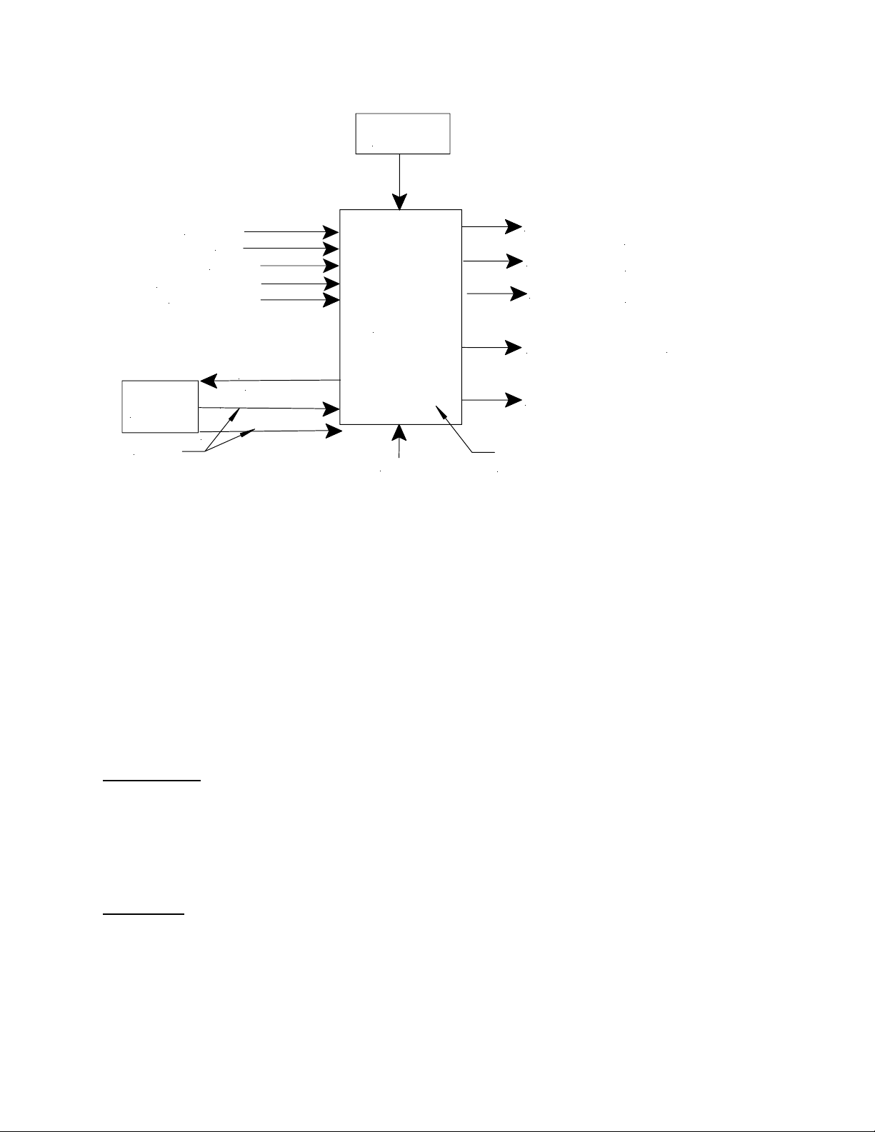
MICROPHONE
TELEPHONE PAGE PORT
BACKGROUND MUSIC
CONTROL
SYSTEM
9 TO 31VDC
AUX IN
NIGHT RING
TROUBLE
RELAY
STROBE NAC INPUT
UP TO 3 NAC CIRCUIT INPUTS
BATTERY
STANDBY
SPEAKER CIRCUIT
STROBE CIRCUIT
STROBE RETURN
SP40/2
PANEL
CONSTANT 24VDC AT 0.5A
ALARM RELAY FORM C
DIGITAL VOICE MESSAGE CHIP ALLOWS RECORDING 3 MESSAGE
SEGMENTS AT THE PANEL. THE PANEL COMES WITH 3 STANDARD
120VAC
Figure 2-1
Basic Capabilities of the SP40/2 Panel
PRE-RECORDED MESSAGES. TAILORED MESSAGES CAN BE
RECORDED AT WHEELOCK.
CENTRAL AMPLIFIED
(40 WATT, SELECTABLE
25V or 70.7V)
POWER LIMITED
24VDC AT 2A MAX.
POWER LIMITED
FOR CONTINUATION OF
STROBE CIRCUIT OR EOLR.
POWER LIMITED
Section 2-4 - Operation Modes
The SP40/2 has two operation modes in the Voice Evacuation Modes:
1. Standby
2. Alarm
Standby Mode
Standby is the normal mode. The SP40/2 panel supervises the connections and internal components to
maintain proper operation. All strobes and speaker appliances are off.
The SP40/2 can also be used as a paging system with background music and night ring.
Alarm Mode
Alarm mode occurs when an emergency signal is initiated by the Fire Alarm Control Panel (FACP) or
control equipment.
NOTE: Telephone paging is not available when the SP40/2 is in the alarm mode.
2-4
Page 17
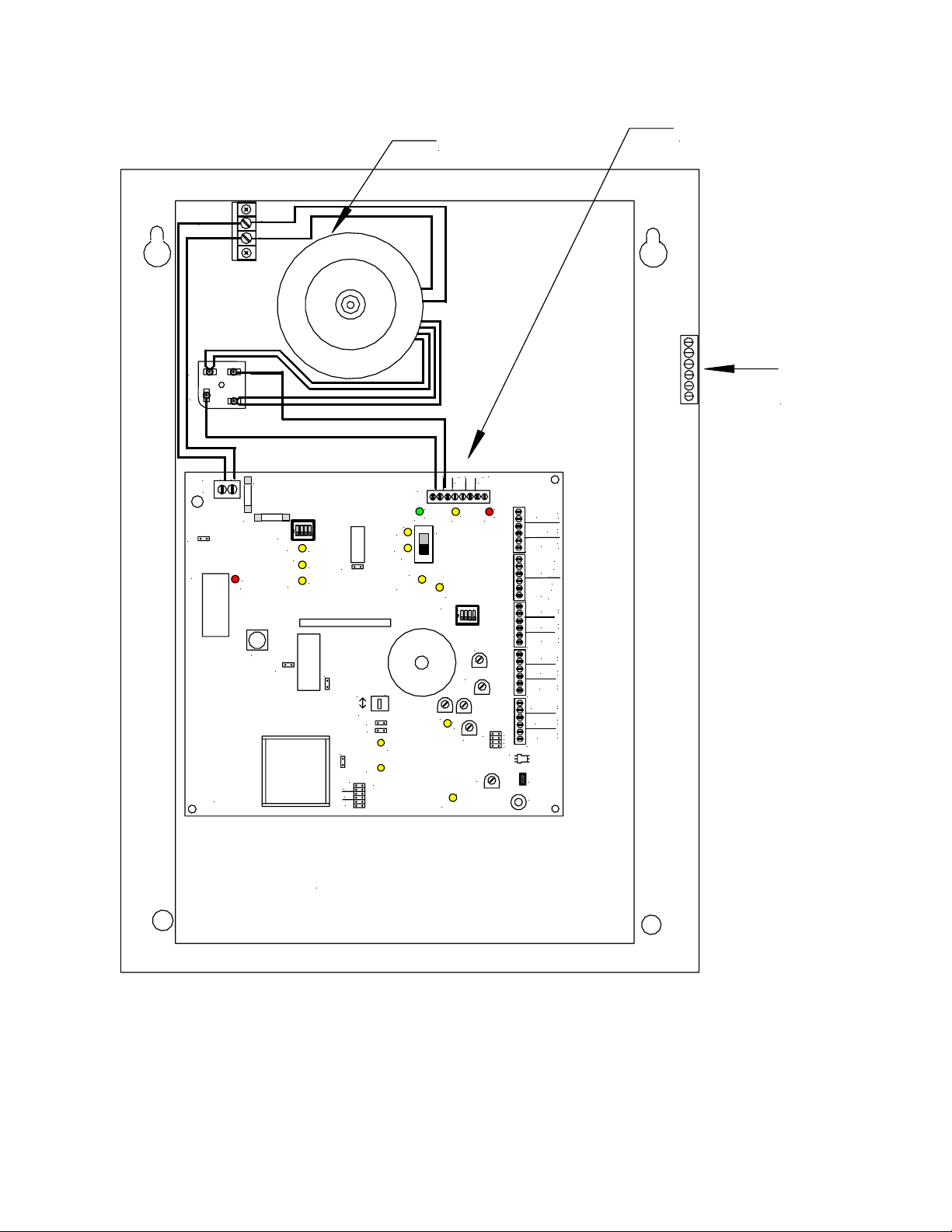
Transformer
Motherboard
L
N
Grounding
AC
+
_
_
_
+
+
24V
BAT
STB
TBL
YEL
RED
D13
D14
D39
STB
OPEN
R
1
2 3
SW3
4
2 3
1
ON
TEL
BGM
TONE
D49
AUX
IN
GF
D60
1V
J2
25V
AUX
70V
100V
J3
DV
TB2
TB3
TB4
TB5
AUDIO OUT
CC/NAC
TB6
W6
E1
STB OUT
STB IN
A
L
M
T
R
B
IN3
IN2
IN1
NR
TEL
BGM
AUX IN
+
_
+
RET
_
+
_
NO
NC
COM
NO
NC
COM
+
_
+
_
+
_
+
_
+
_
+
_
+
_
+
_
+
_
D9
D10
STB
SHORT
+
IN
TB1
AC
GRN
D11
AC
SW1
BAT
D37
L
N
AC
TB7
W1
U8
P84014 REV
F1
RECORD
D34
MIC1
F2
4
2 3
1
ON
SW2
D22
DV
D35
MIC
W2
AMP
D36
W8
W3
SW4
NAC
CC
W5
W4
D54
AUDIO
W7
SHORT
D58
AUDIO
J4
OPEN
100V
70V
25V
Te r mi n a l
Block
Battery Compartment
Figure 2-2.
Layout of SP40/2 Panel
2-5
Page 18

Intentionally Blank
2-6
Page 19

Chapter 3 - Installation and Setup
Section 3-1 - Introduction
The lives of people depend upon your safe and proper installation of the SP40/2 panel. Please read,
understand and carefully follow the specific installation instructions set forth below to avoid damage to the
SP40/2 panel and equipment connected to it. Only qualified personnel in accordance with the procedures
in this manual should conduct installation.
WARNING: SHUT OFF ALL POWER BEFORE STARTING THE INSTALLATION. ELECTRICAL
SHOCK CAN CAUSE DEATH OR SERIOUS INJURY.
WARNING: DO NOT CONNECT AC POWER OR BATTERY BACKUP POWER UNTIL SYSTEM
WIRING HAS BEEN CONNECTED, MODULES HAVE BEEN INSTALLED, AND FIELD WIRING HAS
BEEN INSPECTED.
CAUTION: The SP40/2 printed circuit board is sensitive to static electricity and has delicate
components mounted on it. Before handling the board or any component on it, discharge any static
electricity from your body by touching a grounded object such as a metal screw, which is connected to
earth, ground. The SP40/2 panel is to be installed in a static free area and the user is to properly attach
grounded wrist straps before touching any static sensitive areas.
The installer, prior to installation should consult with the authorities having jurisdiction (AHJ).
Section 3-2 - Fire Alarm Control Panel Wiring Applications
The SP40/2 Digital Voice Section inputs and the strobe input require an 9 to 31VDC. The Fire Alarm
Control Panel (FACP) NAC Circuit of 12VDC or 24VDC will initiate these circuits. The strobe input NAC
can be operated separately from the Digital Voice NAC circuits.
“TROUBLE”, Form C relay terminals and an internal sounder are available for monitoring the condition of
the SP40/2 panel.
Section 3-3 - General Installation Instructions
Refer to Figure 3-1 on Page 3-2, which shows the location of wiring connections used in the installation of
the SP40/2 panel. Table 3-1 on Page 3-3 explains the functions of the different wiring connections.
3-1
Page 20
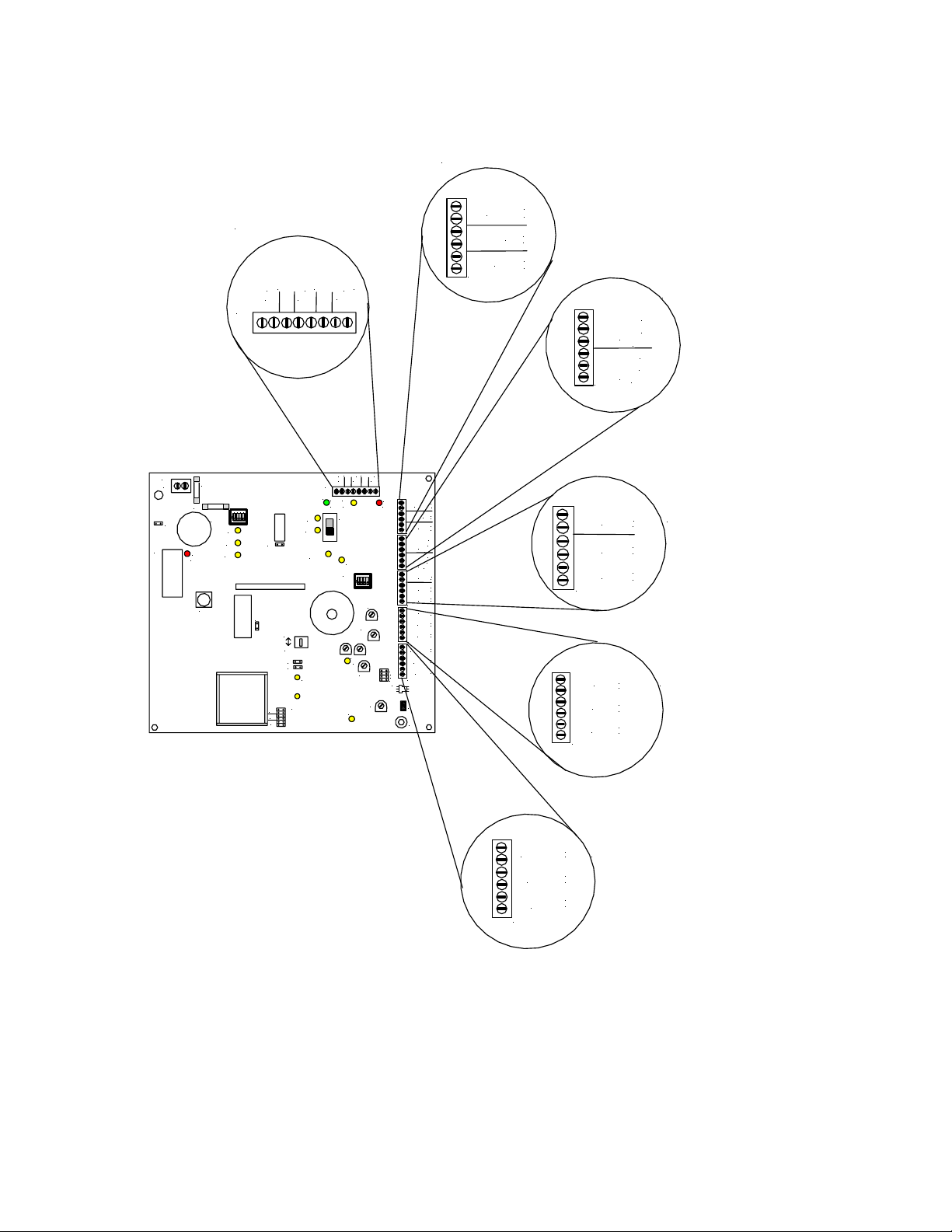
Section 2
Strobe Connections
Section 1
Power Input Connections
_
_
+
+
BAT
IN
24V
_
+
TB1
_
_
+
L
N
AC
F2
TB7
F1
W1
U8
RECORD
D31
4
2 3
1
ON
SW2
DV
MIC
W2
AMP
MIC1
W3
100V
70V
25V
TB1
D11
AC
BAT
STB
SHORT
NAC
CC
W5
W4
AUDIO
SHORT
AUDIO
OPEN
+_+
24V
BAT
IN
TBL
AC
GRN
STB
YEL
SW1
STB
OPEN
3
R
1
2
SW3
4
2 3
1
ON
TEL
BGM
TONE
AUX
IN
AUX
GF
STB OUT
RED
STB IN
TB2
A
L
M
T
R
B
TB3
IN3
IN2
IN1
TB4
NR
TEL
BGM
TB5
AUDIO OUT
CC/NAC
1V
AUX IN
25V
70V
TB6
100V
J3
DV
W6
E1
TB2
+
_
+
RET
_
+
_
NO
NC
COM
NC
NO
COM
+
_
+
_
+
_
+
_
+
_
+
_
+
_
+
_
+
_
STB OUT
RET
STB IN
+
_
+
_
+
_
Section 3
Alarm and Trouble Connections
A
NO
L
NC
M
COM
NC
T
R
NO
B
COM
TB3
Section 4
Internal Digital Voice
+
Module Input Connections
_
+
_
+
_
TB4
IN3
IN2
IN1
Section 5
Night Ring, Telephone Page,
+
NR
TEL
BGM
TB5
Background Music Connections
_
+
_
+
_
Section 6
Audio Output Connections
+
AUDIO OUT
CC/NAC
AUX IN
Auxiliary Input Connections
_
+
_
+
_
TB6
Figure 3-1
Location of Field Wiring Connections
3-2
Page 21

Table 3-1
Terminal Connection Definitions
TB1
TB2
TB3
TB4
TB5
TB6
TB7
Symbol Full Name Definition
IN 28VDC Input Connection 28VDC Connection from Rectifier Module
BAT Battery Input Connection 24VDC, 12AH Battery Input Connection
24V 24VDC 0.5A Output 24VDC, 0.5A Continuous Output Connection, Power Limited auxiliary power
STB OUT Strobe Output 24VDC, 2A Maximum Strobe NAC Output Supervised with UL Listed 10K
RET Return Strobe Input Return for connecting additional strobe circuits, or UL Listed
STB IN Strobe Input 9-31VDC Strobe NAC Input. Triggers Strobes in Alarm Condition
ALM ALARM CONNECTIONS Alarm Form C relay changes state in Audio Alarm Conditions. These
NO Normally Open Alarm Relay contact open to Common (COM) in non alarm condition.
NC Normally Closed Alarm Relay contact closed to Common (COM) in non alarm condition.
COM Common Alarm Relay Common (COM)
TRB TROUBLE CONNECTIONS Trouble Form C relay changes state in panel trouble condition. Contacts are
NO Normally Open Trouble Relay contact open to Common (COM) in non alarm condition
NC Normally Closed Trouble Relay contact closed to Common (COM) in non alarm condition
COM Common Trouble Relay Common (COM)
IN3 Input 3 Digital Voice initiating connection for message #3. (9-31VDC). Input 3 is a
IN2 Input 2 Digital Voice initiating connection for message #2. (9-31VDC). Input 2 is a
IN1 Input 1 Digital Voice Initiating Connection for message #1. (9-31VDC). Input 1 is a
NR Night Ring Contact Closure Input initiates chime sound for Night Ring. Non-supervised.
TEL Telephone Page Input Telephone Page Input from a telephone Page Port. Non-Supervised.
BGM Background Music Input Line Level, 600 Ohm Background Music Input. Automatically mutes when
AUDIO OUT Audio Output Audio Output for 25V or 70V speakers. Supervised using UL Listed 10K
CC/NAC Contact Closure/NAC Contact closure or NAC will initiate AUX IN Audio. CC is supervised.
AUX IN Auxiliary Input Audio Line Level Audio Input from RMX or Remote MIC
AC AC Monitor Input Monitors the AC input voltage and senses when the voltage is too low or not
Terminal Block 1 (Section 1)
Terminal Block 2 (Section 2)
Terminal Block 3 (Section 3)
Terminal Block 4 (Section 4)
Terminal Block 5 (Section 5)
Terminal Block 6 (Section 6)
Terminal Block 7
source
Ohm, ½ W EOLR. (Power limited)
10K Ohm, ½ W EOLR.
conditions are: Push-to-talk Button on MIC depressed. AUX initiated via CC
or NAC, and IN1, IN2, and IN3 inputs present. Contacts are rated at 24VDC,
2A. Resistive load.
rated at 24VDC, 2A. Resistive load.
Priority 5 circuit. Reverse polarity.
Priority 4 circuit. Reverse polarity.
Priority 3 circuit. Reverse polarity.
Night Ring does not operate without 120VAC input and the Panel is
operating on Battery.
Telephone Page does not operate without 120VAC input and the Panel is
operating on Battery.
any other input is in use. Non-Supervised. Background Music input does not
operate without 120VAC input and the panel is operating on Battery
Ohm, ½ W EOLR. Power Limited.
Connects to RMX or Remote MIC
present and energizes the battery circuit. See Figure 7-2 (Page 7-8)
NOTE: All Outputs (Strobe Output, Audio Output, and 24VDC Auxiliary Power Source) are
power limited circuits.
3-3
Page 22

Prepare a System Wiring Diagram
Using Section 3-4 (Page 3-8), prepare a complete system-wiring diagram.
Keep a copy of the system-wiring diagram with the SP40/2 manual as a permanent record of the
system wiring.
Unpack and Inventory
Carefully unpack the SP40/2 panel and make sure each item described on the packing slip is present
and undamaged.
Mounting
1. Mount the SP40/2 panel and optional expansion modules in the desired locations as described in
Section 3-5 (Page 3-13).
2. Mount any additional wiring boxes or junction boxes needed to interconnect field wiring.
3. Connect conduit fittings or bushings as needed through the knockouts provided on the top and
bottom of the SP40/2 panel.
Field Wiring Connections
NOTE: The terminal blocks on the SP40/2 are removable. To remove a terminal block, pull the block
straight up from the circuit board, as shown in Figure 3-2. Attach wires to the desired connections,
then plug the terminal block back on the board being careful to match the pins.
Figure 3-2
Removable Terminal Block
NOTE: For power limited circuits all input power sources (Alarm and Trouble relay
connections, NAC inputs, and auxiliary inputs) must be power limited.
NOTE: The AC Power input wiring is non-power limited and shall be routed on the left side of the
enclosure. All power limited inputs and outputs shall be routed on the right side of the enclosure.
Install field wiring in conduit when required, following the most current National Electrical Code
(NFPA-70) and local codes for the type of system being installed. Make all necessary connections at
any additional wiring or junction boxes.
CAUTION: Provide proper strain relief for all wiring not in conduit.
NOTE: Shielded wire is not required on any circuit. If shielded wire is used, connect the shields to
the ground terminal strip as shown in Figure 3-14 on Page 3-14.
3-4
Page 23

Strobe Appliance Circuit Connections
The strobe appliance circuit consists of a NAC (9 to 31VDC) input and a supervised NAC (24VDC)
Output. As described in Table 3-1 on Page 3-3, the strobe output provides a synchronized output for
compatible Wheelock, Inc. synchronized strobes. When a synchronized signal from a previous
module is used open Jumper W2 (See Figure 3-15, Page 3-15). This also allows for pass through of
the synchronized NAC Circuit on the RET connections. See Figure 3-1, Section 2 on Page 3-2 for
location. Figure 3-3, below, is an enlarged picture of the referred area.
Section 2
+
STB OUT
RET
STB IN
TB2
Figure 3-3
Strobe Input and Output Connections
1. Connect strobe appliance circuit to Strobe NAC Circuit output STB OUT connection on TB2.
Observe correct polarity. See Figure 3-1, Section 2 (Page 3-2) for location. Figure 3-3 is an
enlarged picture of the referred area. The Strobe Appliance Output NAC Circuit is supervised. A
UL Listed 10K Ohm, ½ W EOLR is required at the end of the circuit for proper supervision.
Strobe Connections
_
+
_
+
_
NOTE: The strobe output circuit can be activated two ways. If the strobe output is to be
activated when one or all the digital voice messages are initiated, operate DIP switch SW2 as
explained in Table 3-2 on Page 3-16. The second way is to connect a NAC circuit input from
an FACP to STB IN as described in step 8 below
2. Connect Strobe NAC Circuit input (9 to 31VDC) from the FACP or other UL Listed control panels
to the Strobe Input circuit (STB IN) connection on TB2. Observe correct polarity. See Figure 3-1,
Section 2 for location. Figure 3-3 is an enlarged picture of the referred area.
3. Connect the FACP EOLR, additional appliances or additional SP40/2 panels to RET connection
on TB2. See Figure 3-1, Section 2 for location. Figure 3-3 is an enlarged picture of the referred
area.
Audio Output and Auxiliary Circuit Connections
CC/NAC
AUX IN
+
_
+
_
+
_
AUDIO OUT
TB6
Section 6
Audio Output Connections
Auxiliary Input Connections
Figure 3-4
Audio Output and AUX Input Connections
3-5
Page 24

1. Connect Audio Appliance Circuit to Audio Output (AUDIO OUT) connection on TB6. See Figure
3-1, Section 6 (Page 3-2) for location. Figure 3-4, above, is an enlarged picture of the referred
area. The Audio Output is supervised. A UL Listed 10K Ohm, ½ W EOLR is required at the end
of the circuit for proper supervision.
2. Select the proper output voltage (25V or 70V) using the Audio Output Select Jumper J4. See
Figure 3-15 (Page 3-15) for location.
3. Refer to Remote MIC or RMX Installation Manual for proper connections from AUX IN and
CC/NAC to these products.
Audio Input Connections
The SP40/2 panel has 8 inputs. The highest priority input is the on board push-to-talk Microphone. It
overrides all other audio inputs. The second highest priority input is the AUX. This could be a
Remote MIC or RMX. Next are the IN1, IN2 and IN3 respectively, followed by Night Ring (NR),
Telephone Page (TEL), and Background Music (BGM). Background Music will be muted when any
other audio input is initiated. Night Ring (NR), Telephone Page (TEL), and Background Music (BGM)
operate only when the panel has 120VAC applied.
Digital Voice Initiating Connections
The Digital Voice Initiating Connections (IN1, IN2, IN3) provide the initiation of the stored messages
in the Digital Voice Section of the SP40/2 panel. Each initiation circuit requires a NAC (9 to 31VDC)
input to trigger the respective voice message. Each Initiating circuit is polarized for compatibility with
standard reverse polarity supervision of circuit wiring. Additional information can be found in Table 31 on Page 3-3.
The Digital Voice Initiating Connections (IN1, IN2, IN3) can also initiate the strobe NAC output circuit.
Using DIP Switch SW2 (Strobe Select Sync/Non-Sync Select), strobes can be initiated by IN1, IN2,
and/or IN3. (See Figure 3-15 on Page 3-15). Positions 1, 2, and 3 control the strobe initiation for
inputs IN1, IN2, and IN3 respectively. Positioned in the ON or up position causes the strobes to
operate during message playback. Position 4 (OFF) selects the Wheelock Sync Mode.
+
IN3
_
+
IN2
_
Section 4
+
IN1
_
TB4
Internal Digital Voice
Module Input Connections
Figure 3-5
Digital Voice Initiating Connections
While observing correct polarity, connect the Digital Voice Initiating connections (IN1, IN2, IN3) to the
connections on TB4 as desired. Connect FACP EOLR across desired IN1 through IN3. See Figure 31, Section 4 on Page 3-2 for location. Figure 3-5, on Page 3-6, is an enlarged picture of the referred
area.
Ancillary Audio Input Connections
The SP40/2 panel has three ancillary audio inputs. Listed in order of priority, they are Night Ring
(NR), Telephone Page (TEL), and Background Music (BGM). These inputs will not operate when
the SP40/2 is in the alarm condition or when the input voltage (120VAC) is not applied and the
SP40/2 is on battery backup. These inputs are not supervised. The Telephone Page input requires
input from a Telephone Page Port. The Night Ring input requires a dry contact closure. The
Background Music input requires a line level, 600 Ohm, 1Vrms signal.
3-6
Page 25

NOTE: Amplifier noise can be reduced by placing a jumper wire between the positive (+) and
negative (-) terminals of the Background Music Input (BGM) and/or the Telephone Page Input (TEL)
when these inputs are not in use. If the BGM is being used and the TEL is not, place a jumper wire on
the TEL input. If the TEL is being used and the BGM is not, place a jumper wire on the BGM input.
1. Connect Telephone Page Input (TEL) to TB5. See Figure 3-1, Section 5 on Page 3-2 for location.
Figure 3-6, below is an enlarged picture of the referred area.
2. Connect Night Ring Input (NR) to TB5. See Figure 3-1, Section 5 on Page 3-2 for location.
Figure 3-6, below, is an enlarged picture of the referred area.
NOTE: The Night Ring (NR) input requires a contact closure from the phone system to activate. The
NR must be connected to the phone line in the same room.
+
NR
_
+
TEL
_
+
BGM
TB5
_
Section 5
Night Ring, Telephone Page,
Background Music Connections
Figure 3-6
Ancillary Audio Input Connections
3. Connect Background Music Input (BGM) to TB5. See Figure 3-1, Section 5 on Page 3-2 for
location. Figure 3-6, above, is an enlarged picture of the referenced area.
WARNING: EXCESSIVE BGM VOLTAGE INPUT CAN CAUSE AMPLIFIER FAILURE. THE
PREFERRED AUDIO SOURCE OUTPUT FOR THE BGM INPUT OF THE SP40/2 (CD PLAYER, TUNER,
EQUILIZER, ETC.) SHALL BE A FIXED LINE LEVEL VOLTAGE LESS THAN 2.5V PEAK TO PEAK OR
300mV RMS. AUDIO SOURCES MARKED “LINE LEVEL OUTPUT” WILL TYPICALLY BE WITHIN
THIS LIMIT. AUDIO SOURCES WITH OTHER THAN FIXED LINE LEVEL OUTPUTS (I.E.,
ADJUSTABLE SPEAKER OUTPUTS, ETC.) REQUIRE THAT THE AUDIO SOURCE BE ADJUSTED
USING A MULTIMETER ACROSS THE OUTPUT OF THE SIGNAL SOURCE (SEE PROCEDURE
BELOW). ONCE THE LEVEL HAS BEEN SET PROPERLY, SECURE THE ADJUSTABLE AUDIO
SOURCE SO THAT THE LEVEL CANNOT BE INADVERTENTLY CHANGED. FAILURE TO SET
ADJUSTABLE AUDIO SOURCES APPROPRIATELY OR FAILURE TO SECURE AUDIO ADJUSTABLE
SOURCES CAN LEAD TO FAILURE OF THE AMPLIFIER SECTION OF THE SP40/2. THIS FAILURE,
IN TURN, COULD RESULT IN PROPERTY DAMAGE AND SERIOUS INJURY OR DEATH TO YOU
AND/OR OTHERS.
NOTE: WHEN INSTALLED IN NYC, THE BGM FEATURE IS NOT PERMISSIBLE.
NOTE: WHEN INSTALLED IN NYC, THE TELEPHONE PAGING FEATURE IS NOT PERMISSIBLE.
Setting Adjustable Audio BGM Sources for the SP40/2
NOTE: Use a good multimeter that provides true RMS readings in the AC voltage scale and
calculates the results through average sampling. Some multimeters can select instant or average
sampling readings. This adjustment shall always be done in the averaging mode. Most digital
multimeters use the average sampling method in the “AC Volts RMS” setting.
1. Insure that power is disconnected from the SP40/2.
2. Set Audio Source volume control to minimum setting.
3. Connect the Audio Source output to the BGM input terminals on the SP40/2.
3-7
Page 26

4. Set the multimeter to the AC Volts scale, which is capable of reading 300mV RMS.
5. Connect the multimeter across the BGM terminals on the SP40/2.
6. Adjust the output control of the audio source to obtain a reading of 300mV RMS on the
multimeter.
7. Secure the output control of the audio source so that it cannot be inadvertently changed.
8. Disconnect multimeter. The output of the Audio Source is now correctly set for the SP40/2 BGM
input.
Alarm and Trouble Output Connections
The Alarm Form C relay contacts change state when certain audio inputs are in alarm. The Trouble
Form C relay contacts change state when the panel goes into any trouble condition. See Table 3-1
on Page 3-3 for additional information.
A
NO
L
NC
M
COM
NO
T
R
NC
B
COM
TB3
Section 3
Alarm and Trouble Connections
Figure 3-7
Alarm and Trouble Connections
1. Connect External alarm circuit to the proper Alarm (ALM) connections. See Figure 3-1, Section 3
on Page 3-2 for location. Figure 3-7, above, is an enlarged picture of the referred area.
2. Connect External Trouble circuit to the proper Trouble (TRB) connections. See Figure 3-1,
Section 3 on Page 3-2 for location. Figure 3-7, above, is an enlarged picture of the referred area.
3. Connect the SP40/2 panel to earth ground, following the National Electrical Code and local codes
for the type of system being installed. Wire gauge selection of the earth ground wiring should
involve consideration of all factors, including maximum allowable wire resistance and length. The
panel is tied to earth ground by connecting the ground terminals to an earth ground. The location
of the ground terminals within the panel is shown in Figure 3-16 on Page 3-21.
CAUTION: Do not connect input voltage to any equipment until the field wiring has been tested,
inspected and approved.
4. Check the integrity of all field wiring. Confirm that the specified cable is installed, and that there is
continuity between required points (no open circuits), with no unwanted shorts to other
conductors, chassis, or earth ground.
a. Verify that the field wiring complies with the instructions of this manual and the detailed wiring
diagram prepared for this installation.
b. Ensure that no unwanted voltages are present on circuit conductors and ground.
c. Test all ungrounded connectors for electrical isolation from ground.
d. Measure and record the resistance of each NAC circuit. Conduct this test reversing polarity.
5. Perform Ground Fault Installation Procedure as described in Section 3-7 (Page 3-19).
6. Calculate and Install properly sized backup batteries as described in Section 3-8 (Page 3-19) and
3-9 (Page 3-21). The SP40/2 is UL approved for 24VDC at 12AH.
3-8
Page 27

WARNING: TWO DIFFERENT SOURCES OF POWER MAY BE CONNECTED TO THIS UNIT.
DISCONNECT BOTH SOURCES OF POWER BEFORE SERVICING. FAILURE TO DISCONNECT
BOTH POWER SOURCES BEFORE SERVICING COULD RESULT IN PROPERTY DAMAGE,
SERIOUS INJURY, OR DEATH TO YOU AND/OR OTHERS.
WARNING: ALWAYS APPLY AC VOLTAGE BEFORE APPLYING BATTERY BACKUP
VOLTAGE. FAILURE TO DO SO MAY CAUSE DAMAGE TO THE SP40/2 PANEL.
7. Perform System Checkout Procedures as described in Section 3-6 System Checkout on Page
3-14.
Section 3-4 – Prepare a System Wiring Diagram
Wiring Guidelines
Although the SP40/2 panel incorporates signal verification and noise filtering circuitry on their inputs,
induced voltages or noise on the input wiring can cause improper operation. Therefore, use shielded
twisted pair wire for all dry contact input wiring.
The shield of each cable should be connected only at one end. Each shield of each cable that
connects to the SP40/2 panel is to be connected to the grounding points provided near the
knockout locations on the chassis (see Figure 3-14 on Page 3-14).
The National Electrical Code defines two types of circuits for protective signaling systems: powerlimited circuits and non-power limited circuits. All SP40/2 outputs (STB OUT, AUDIO OUT, and
±24VDC auxiliary power source) are power-limited circuits.
WARNING: ALL SP40/2 AUDIO WIRING SHOULD BE ROUTED AWAY FROM ANY HIGH
VOLTAGE OR HIGH CURRENT WIRING (SUCH AS AC OR DC POWER WIRING, AUDIO POWER
WIRING, AND MOTOR OR RELAY ACTUATION WIRING). FAILURE TO DO SO MAY CAUSE
ELECTRICAL SHOCK RESULTING IN PROPERTY DAMAGE AND SERIOUS INJURY OR DEATH
TO YOU AND/OR OTHERS.
CAUTION: The National Electric Code limits the maximum number of conductors that can be
installed in conduit and wiring boxes depending on the size of the conduit, the volume of the boxes,
and the gauge of the wire used. Make sure that wiring used for SP40/2 installation complies with the
latest NEC, NFPA, Local, State, County or Province requirements.
Field Wiring Connections
All SP40/2 wiring terminals are designed to accept #12 AWG through #22 AWG wiring for one
wire per terminal or #16 AWG to #22 AWG for two wires per terminal. Proper wire gauge
considerations for the Notification Circuit must take into account current requirements versus length
of run.
NOTE: Only speakers with DC blocking capacitors will provide for proper speaker
supervision.
3-9
Page 28

Prepare System Wiring Diagram
Prepare a system-wiring diagram to include all Notification Appliances, and internal connections and
power sources as required.
NOTE: Separate input power wiring from the other input and output wiring. Wire the input
power to the left side of the motherboard (Figure 3-16, Page 3-21) and the other input and
output wiring to the right.
Visual Notification Appliance Output Wiring
● Wire gauge selection involves consideration of all factors including, wire loop length, maximum
current draw of each appliance, number of appliances, and maximum voltage drop allowable.
● Strobe NAC has a 24VDC, 2.0 amps maximum output.
● Strobe NAC meets Class B supervision requirements for notification appliance circuits.
● The strobe output circuit shall have a UL Listed 10K Ohm, ½ W EOLR installed across the last
visual notification appliance. If the output is unused, a UL Listed 10K Ohm, ½ W EOLR shall be
placed across the output terminals.
Speaker Notification Appliance Output Wiring
Wire gauge may vary for each audio appliance output on the panel. When:
● Speaker (with transformer) appliances are used with supervised audio amplifier module. Wire
gauge selection should involve consideration of all factors including, wire length, appliance power
ratings, and the number of appliances.
● The amplified output is either a selectable 25 or 70.7Vrms audio output, rated for 40 watts
maximum.
● The output meets Class B supervision requirements for notification appliance circuits.
● The audio output circuit shall have a UL Listed 10K Ohm, ½ W EOLR installed across the last
notification appliance. If the output is unused, it shall have a UL Listed 10K Ohm, ½ W EOLR
across the output terminals.
3-10
Page 29

Wiring Diagrams for Audio/Visual Notification Appliances
STB OUT
connection.
connection.
+
_
TB2-1, 2
UL Listed
10K Ohm
EOLR
Figure 3-8
Wiring Diagram for Visual Only Notification Appliances
CAUTION: Do not loop wire under terminals. Break wire run to provide supervision of
STB OUT
TB2-1,2
AUDIO OUT
TB6-1,2
+
_
+
_
UL Listed
10K Ohm
EOLR
UL Listed
10K Ohm
EOLR
Figure 3-9
Wiring Diagram for Combination Audio/Visual Notification Appliances
CAUTION: Do not loop wire under terminals. Break wire run to provide supervision of
AUDIO OUT
TB6-1,2
+
_
UL Listed
10K Ohm
EOLR
Figure 3-10
Wiring Diagram for Audio Only Notification Appliance Output
CAUTION: Do not loop wire under terminals. Break wire run to provide supervision of
connection.
3-11
Page 30

Strobe Appliance Circuit Input Wiring
The Strobe Appliance Circuit Input consists of a NAC (9 to 31VDC) input and a Return (RET) that
can be used for additional appliances or FACP end of line resistor. The output is a supervised
NAC (24VDC) Circuit. As described in Table 3-1 on Page 3-3 this output can provide a
synchronized output for compatible Wheelock, Inc. synchronized strobes. When a synchronized
signal from a previous module is used open Jumper W2 (Figure 3-15, Page 3-15).
Auxiliary Input Wiring
Refer to RMX (P84557) or Remote MIC (P84207) Installation Manual for proper wiring to these
products. CC Input is supervised by the SP40. AUX IN connection is supervised by the RMX or
Remote MIC.
Digital Voice Initiating Input Wiring
The Digital Voice Initiating Connections (IN1, IN2, IN3) provide the initiation of the stored
messages in the Digital Voice Section of the SP40/2 panel. Each initiation circuit requires a NAC
(9 to 31VDC) input to trigger the respective voice message. Each initiating circuit has a blocking
diode that allows supervision of the input wiring. Additional information can be found in Table 3-1
on Page 3-3.
The Digital Voice Initiating Connections can also be used to initiate the strobe circuit when the
voice message is initiated. DIP Switch SW2 controls the strobe circuit for one or all voice
messages.
Ancillary Audio Input Wiring
The SP40/2 panel has three ancillary audio inputs. Listed in order of priority, Night Ring (NR),
Telephone Page (TEL), and Background Music (BGM). These inputs are not supervised. The
Night Ring input requires a dry contact closure. The Telephone Page input requires an input from
a Telephone Page Port. The Background Music input requires line level, 600 Ohm, 1Vrms signal.
NOTE: WHEN INSTALLED IN NYC, THE BGM FEATURE IS NOT PERMISSABLE.
NOTE: WHEN INSTALLED IN NYC, THE TELEPHONE PAGING FEATURE IS NOT PERMISSABLE.
Alarm and Trouble Output Wiring
The Alarm Form C relay contacts change state when certain audio inputs are in alarm. The
Trouble Form C relay contacts change state when the panel goes into any trouble condition. See
Table 3-1 on Page 3-3 for additional information.
WARNING: IT IS IMPORTANT THAT THE WIRING USED FOR INPUT VOLTAGE WIRING IS LARGE
ENOUGH TO CARRY THE MAXIMUM CURRENT REQUIRED BY THE SP40/2 PANEL WITHOUT
EXCESSIVE VOLTAGE DROP. IF VOLTAGE DROPS FROM AC POWER LINE LOADING AND WIRING
RESISTANCE IS NOT WITHIN THE SPECIFIED OPERATING VOLTAGE RANGE, THE SP40/2 PANEL
WILL NOT FUNCTION PROPERLY.
Alarm Output Contact Wiring
The location of the Alarm Output Connections is shown in Figure 3-1 Section 3 (Page 3-2). A
magnified view of this area on the Mother Board is shown in Figure 3-7 on Page 3-7.
• Wire gauge selection of the Alarm Status output contact wiring should involve consideration of
all factors including, wire loop length, maximum current capacity, and maximum voltage drop
allowable.
• The Alarm Status output contact is Form C, rated for 2.0 amps at 24VDC, resistive load.
• For terminal connection details of the Alarm Status output contact (shown in the non-alarm
mode) see Figure 3-11, below.
• An external 24VDC or the internal 24VDC connection (TB1) can be used to power non-
supervised Alarm appliances. See Figure 3-1, Section 1 (Page 3-2) for location of TB1.
3-12
Page 31

TB3
NO
A
NC
L
M
COM
Figure 3-11
Alarm Relay Contacts
Trouble Output Contact Wiring
• The locations of the Trouble Status Output Connections are shown in Figure 3-1 Section 1
(Page 3-2). A magnified view of this area on the Mother Board is shown in Figure 3-7 on
Page 3-7.
• Wire gauge selection of the system Trouble Status output contact wiring should involve
consideration of all factors including, wire length, maximum current capacity, and
maximum voltage drop allowable.
• The system Trouble Status output contact is Form C, rated for 2.0 amps at 24VDC,
resistive load.
• For a detail of the system Trouble Status output contact terminal connections (shown in
the trouble position), see Figure 3-12 below.
• An external 24VDC or the internal 24VDC connection (TB1) can be used to power
Trouble indicating appliances. See Figure 3-1, Section 1 (Page 3-2) for location of TB1.
TB3
NO
T
NC
R
B
COM
Figure 3-12
Trouble Status Relay Contacts
POWER CONNECTION REQUIREMENTS
The SP40/2 contains a 24VDC Power Supply and a Battery Charger for the battery backup.
Connections for the input power and batteries are shown in Figure 3-1, Section 1 (Page 3-2). A
magnified view of this area on the Mother Board is shown in Figure 3-13, below. TB1 is for
battery connection. TB1 has a 24VDC, 0.5A, power limited, auxiliary power source. Calculate
proper backup battery requirements using Section 3-8 – Battery Care and Backup Battery
Calculations.(Page 3-19). Section 3-9 on Page 3-21 is the AC and battery installation
procedures.
3-13
Page 32

Section 1
Power Input Connections
+
BAT
_
+
24V
_
TB1
_
+
IN
Figure 3-13
Input Power and Battery Connection Locations
Proceed to Step 2 in Section 3-3 – General Installation Instructions (Page 3-4).
Section 3-5 - Mounting
Location
The SP40/2 panel shall be mounted in a location within the environmental limits specified in the
latest UL Standard 864 for indoor control panels. The SP40/2 panel shall not be located in a
hazardous area.
CAUTION: In order to comply with the latest NFPA and UL requirements for interconnection
of fire alarm control equipment, the SP40/2 must be located in the same room, and within 20 feet
of, a listed compatible fire alarm control panel. Wiring shall be enclosed in conduit and properly
connected to such control panel.
1. See Figure 3-14 on Page 3-14 for SP40/2 panel mounting hole layout.
2. Mark and drill mounting holes for appropriate screws and anchors to ensure secure
mounting to the type of surface at the selected location.
3. Prevent dust and dirt contamination of the SP40/2 panel during installation. This
contamination can interfere with the operation and reduce the life of the equipment.
4. Open the door and remove the dead front panel, and mount the SP40/2 panel at the
selected location. Use care to avoid damage to the module during installation. Do not
apply excessive pressure to the PC board or its components, including field wiring terminals
and connectors.
5. Proceed to step 4 in Section 3-3 – General Installation Instructions (Page 3-4).
3-14
Page 33

14.00"
Ground
Terminals
Conduit Entrances (Top and Bottom)
Figure 3-14
SP40/2 Panel Mounting and Grounding Location
17.00"
3-15
Page 34

Section 3-6 - System Checkout
Refer to NFPA 72 (1999 Edition) for guidelines on testing notification systems.
System Control Settings
Figure 3-15 on Page 3-15 shows the location of the controls used to configure the SP40/2 Table
3-2, Page 3-16, explains the functions of the different jumpers, switches, and variable resistors.
The following procedure is a basic setup for the panel:
SW1 Trouble Acknowledge
Switch
NAC
CC
SW4
W5
W4
AUDIO
SHORT
AUDIO
OPEN
D11 POWER LED
(Green)
_
+
BAT
IN
TB1
D11
AC
GRN
STB
SHORT
SW1
SW3
STB
OPEN
TONE
GF
AUX
IN
AC
BAT
_
_
+
+
24V
TBL
YEL
3
R
1
2
4
2 3
1
ON
TEL
BGM
AUX
DV
SW2 DV/Strobe Select
Sync/nonSync Select
W1 DV Record
D34 Record LED
DV Record
Microphone
W8 Future Use
W3 Internal Tone
Select
SW4 NAC/Contact
L
N
AC
TB7
W1
U8
F1
RECORD
D34
MIC1
F2
4
2 3
1
ON
SW2
DV
MIC
W2
AMP
W8
W3
W7
100V
70V
25V
Closure Select
W5 Contact Closure
Supervision
W7 Non Alarm
Disabl e
W4 Audio Short
Disabl e
J4 Audio Output
Select
Figure 3-15
Jumper/Switch/Variable Resistor Locations
1. Ensure that the AC and Battery Power are not connected.
2. Plug in the Microphone.
3. Select the proper audio output (25V or 70V) by using the two jumpers on J4 Audio Output
Select.
4. Connect the speaker circuit to terminal block TB6 AUDIO OUT. Verify that the speaker
circuit has a UL Listed 10K Ohm, ½ W EOLR.
5. If applicable, connect the strobe circuit to TB2 STB OUT. Verify that the strobe circuit has
a UL Listed 10K Ohm, ½ W EOLR.
6. If Strobe synchronization is to be defeated, remove Jumper W2 Strobe Synchronization
Defeat.
7. If the Ground Fault feature is not desired, remove Jumper W6 Ground Fault Disable.
Table 3-2
D13 TROUBLE LED (Yellow)
D14 STROBE ALARM LED (Red)
STB
RED
J2
1V
25V
70V
100V
J3
TB2
TB3
TB4
TB5
AUDIO OUT
CC/NAC
TB6
W6
STB OUT
STB IN
A
L
M
T
R
B
IN3
IN2
IN1
NR
TEL
BGM
AUX IN
RET
COM
COM
+
_
+
_
+
_
NO
NC
NO
NC
+
_
+
_
+
_
+
_
+
_
+
_
+
_
+
_
+
_
E1
W2 Strobe Synchronization
Defeat
SW3 Digital Voice
Control DIP Switch
R89 Telephone Page
Vol ume Co nt r ol
R128 Background Music
Volume Control
R126 Tone Control Bass
R129 Tone Control Treble
R158 AUX IN Volume Control
AUX IN Select
J3 Microphone Jack
W6 Ground Fault Disable
Grounding Terminal
R193 Digi tal Voice
Vol ume Co nt r ol
3-16
Page 35

Jumper/Switch/Variable Resistor Functions
Jumpers Name Description
W1 DV Record Jumper in place – DV is in the Playback only mode.
Jumper removed – DV is in the Record and Playback
mode.
W2 Strobe Synchronization Defeat Jumper in place – Wheelock Strobe Sync activated.
Jumper removed – Strobe Synchronization defeated.
Allows for Strobe Sync by a master unit and pass
through on RET connection.
W3 Internal Tone Select Jumper in place – Code 3 Tone
Jumper removed – Slow Whoop Tone
W4 ----------------- Not Used - Jumper shall remain in place .
W5 CC Supervision Disable Jumper in place – CC Supervision Disabled
Jumper removed – CC Supervision Enabled
W6 Ground Fault Disable Jumper in place – Ground Fault Circuit Enabled.
Jumper removed – Ground Fault Circuit Disabled.
W7 Shorted Audio Output Non
Emergency Defeat
W8 ----------------- For future use.
J2 AUX IN Select Select AUX IN Level. Set jumper to IV for use with
J4 Audio Output Select Selects 25V or 70.7V for Audio Output (AUDIO OUT)
Switches Name Description
SW1 Trouble Acknowledge Spring loaded. When depressed, silences the internal
SW2 DV/Strobe Select, Sync/Non-Sync
Select
SW3 Digital Voice Selector Switch Four position DIP Switch. Positions 1, 2, and 3 allow
SW4 NAC/CC Selector Switch Set to CC when using RMX or Remote MIC
Variable
Resistors
R89 (TEL) Telephone Page Volume Control Adjusts Telephone Page Volume
R128 (BGM)
R126 (TONE) Tone Control Treble Adjusts Audio Amplifier Tone (Treble)
R129 (TONE) Tone Control Bass Adjusts Audio Amplifier Tone (Bass)
R158 (AUX) Auxiliary Input Volume Control Adjusts Auxiliary Input Volume
R193 (DV) Digital Voice Volume Control Adjusts Digital Voice Output Volume
Name Description
Background Music Volume
Control
Jumper in place – Telephone Page, BGM, NR
disabled.
Jumper removed – Telephone Page, BGM, NR
enabled
RMX or SPRM
by moving two jumpers.
trouble sounder.
Four position DIP Switch. Positions 1, 2, and 3 allow
strobe activation when IN1, IN2, and/or IN3 are
initiated respectively.
Position 4 controls Wheelock Sync (OFF) or Non-Sync
(ON) mode for Switch SW2 only.
playback of the three messages when Jumper W1 is in
place.
Position 4 controls record mode when Jumper W1 is
removed.
Adjusts Background Music Volume
3-17
Page 36

Checkout Procedure.
CAUTION: Connect the AC power source before connecting the battery backup power.
Disconnect the battery backup power before disconnecting the AC power source.
NOTE: All switches, jacks and jumpers are illustrated in Figure 3-15 on Page 3-15.
1. Connect AC power, then connect battery backup.
NOTE: When the AC power source is applied to the panel, the battery voltage check
circuitry is activated. If batteries are not connected within 20 seconds the panel trouble
circuit will be activated. The battery voltage check circuitry will re-check for batteries
every 2 minutes. If the batteries are installed during the 2 minute period, the panel will
remain in trouble until the next re-check.
D11 AC LED (Green) should be “ON” to indicate normal operation. If LED D11 is “OFF”, LED
D13 TROUBLE LED (Yellow) is “ON”, and the internal sounder is operating, a trouble condition is
indicated. STOP TESTING
problem before you resume testing. See Figure 3-15 on Page 3-15 for location of LEDs.
Perform the following tests:
NOTE: Adjust tone to the desired level by turning potentiometers R126 (treble) and R129
(bass) to the desired levels.
Microphone Test
. Refer to Chapter 7 of this manual, troubleshoot and correct the
2. Press the push-to-talk Button on the microphone and speak into the Mic. Insure voice can be
heard on the output speaker circuit.
Auxiliary Test
3. If a Remote MIC or RMX is being used initiate a Remote MIC and speak into the MIC. Insure
voice can be heard on the output speaker circuit.
Digital Voice Message Test
Message 1
4. Switch DIP switch SW3 (Digital Voice Selector Switch), Position 1 “ON”. Message should be
heard on output speaker circuit.
5. The strobe circuit associated with the first message can also be tested by switching DIP
switch SW2 (DV/Strobe Select), position 1 “ON”. The STB LED (Red) will turn “ON”. If the
strobe circuit is attached to TB2, strobes will flash. (See Figure 3-3 on Page 3-5.)
NOTE: If SW2 (DV/STROBE SELECT) switch has positions 1, 2, and/or 3 in the “ON”
position (Figure 3-15, Page 3-15) and the associated digital voice message input (IN1, IN2,
or IN3) is activated, D37 (STB SHORT) LED will illuminate during that alarm condition.
Unless D13 TROUBLE LED is illuminated, there is no trouble condition.
Page 7-2 for location of these LEDs.
See Figure 7-1 on
6. Turn SW3 Position 1 OFF. The message will play to completion. If DIP switch SW2
(DV/Strobe Select), position 1 is ON the strobe circuit will be ON until the message is
complete.
7. Turn DIP switch SW2, position 1 OFF.
3-18
Page 37

8. Apply 24VDC from TB1 (Figure 3-13 on Page 3-13 ) to TB4 (IN1) connection (Figure 3-5 on
Page 3-6 ). Message should be heard from output speaker circuit.
9. The strobe circuit associated with the first message can also be tested by switching DIP
switch SW2 (DV/Strobe Select), position 1 “ON”. The STB LED (Red) will turn “ON”. If the
strobe circuit is attached to TB2, strobes will flash.
10. Remove the 24VDC from TB4 (IN1). The message will play to completion. If DIP switch SW2
(DV/Strobe Select), position 1 is “ON” the strobe circuit will be ON until the message is
complete.
11. Turn DIP switch SW2, position 1 OFF.
12. Perform Steps 3 through 10 on Messages 2 and 3. Use Table 3-1 below.
Table 3-3
Digital Voice Message Tests
Message
Number
TB4
SW3 Digital Voice
Selector Switch
SW2 DV/Strobe
Select
Message 1 IN1 Position1 Position 1
Message 2 IN2 Position 2 Position 2
Message 3 IN3 Position 3 Position 3
Strobe Circuit Test
13. If Strobe circuit is being used separately, apply 24VDC from TB1 (Figure 3-13 on Page 3-13)
to STB IN connection TB2 (Figure 3-3 on Page 3-5 ). Strobes on Strobe Output Circuit
should flash. LED D9 STROBE ALARM (RED) shall be lighted. Remove Voltage
Night Ring Test
14. Test Night Ring by shorting NR connection TB5 (Figure 3-6 on page 3-7). The chime sound
should be heard from the output speaker circuit.
Telephone Page Test
15. If the Telephone Page circuit is used, make a telephone page from the phone system. The
page should be heard from the AUDIO OUT speaker circuit.
Background Music Test
16. If the Background Music circuit is used, energize the music source. The music source output
should be heard from the output speaker circuit.
17. Installation and Checkout procedure is complete. Make and check final connections, replace
dead front panel.
WARNING: ALL PROTECTIVE SIGNALING SYSTEMS REQUIRE PERIODIC TESTING.
ALL PROTECTIVE SIGNALING SYSTEM EQUIPMENT SHALL BE TESTED BY QUALIFIED
PERSONNEL AT LEAST TWICE A YEAR FOR PROPER OPERATION, OR MORE OFTEN IF
REQUIRED BY CODES, REGULATIONS AND LAWS. FAILURE TO MAINTAIN AND TEST
PROTECTIVE SIGNALING SYSTEM EQUIPMENT CAN RESULT IN NOT DETECTING
EQUIPMENT FAILURE THAT CAN CAUSE PROPERTY DAMAGE AND SERIOUS
PERSONAL INJURY OR DEATH TO YOU AND/OR OTHERS DURING AN EMERGENCY
SITUATION.
3-19
Page 38

Section 3-7 – Ground Fault Detection
Ground fault detection sensitivity is 600K Ohms for Class B, Style Y connections. If ground fault
detection is not desired, remove jumper W6. See Figure 3-15 on page 3-15 for location.
Section 3-8 – Battery Care and Backup Battery Calculations
Care of Sealed Lead Acid Batteries
Sealed lead acid batteries are designed to operate in standby service for approximately five
years. This is based upon a normal service condition where there is an ambient temperature of
20 degrees C (68 degrees F) and batteries are completely discharged once every three months.
LENGTH OF SERVICE LIFE WILL BE DIRECTLY AFFECTED BY THE NUMBER OF
DISCHARGE CYCLES, DEPTH OF DISCHARGE, AND AMBIENT TEMPERATURE.
Use Guidelines:
Avoid installation and/or operation in close proximity to heat sources. While the operating
temperature range is 0 to 49 degrees C (32-120 degrees F), battery life will be maximized at an
ambient temperature of 20 degrees C (68 degrees F).
Batteries may generate ignitable gases. Because of this, batteries shall be installed in a wellventilated location, away from spark producing equipment.
Batteries shall not be installed in an atmosphere where organic solvents or adhesives may be
present. The batteries shall not be cleaned with oils, thinners, or similar substances. The case
and cover of the batteries are ABS plastic resin, which may suffer damage from these chemicals.
Batteries shall not be installed in a heavy vibration or shock location.
Insulated gloves shall always be worn when handling batteries.
WARNING: BATTERIES SHALL NOT BE CRUSHED, INCINERATED, OR DISMANTLED.
THE ELECTROLYTE CONTAINS SULFURIC ACID, WHICH CAN CAUSE SERIOUS DAMAGE
TO EYES AND SKIN. IF CONTACT DOES OCCUR, FLUSH WITH WATER AND SEEK
IMMEDIATE MEDICAL ATTENTION.
Batteries of different capacities, age, or manufacturer shall not be used together.
Battery Storage
Batteries which are to be stored for an extended period of time should be given a supplement
charge monthly. Batteries should never be stored in a discharged condition.
The self-discharge rate of batteries is approximately 3% per month when the storage temperature
is maintained at 20 degrees C (68 degrees F). The self-discharge rate will vary depending upon
temperature. Cooler temperatures cause the self-discharge rate to decrease. Warmer
temperatures cause the self-discharge rate to increase.
Calculating Backup Battery Requirements
A Worksheet for assisting in calculating battery backup is available at the end of this manual.
Due to the current drain on the battery, the maximum battery size for the SP40/2 is 12
Amp-hours.
3-20
Page 39

It is necessary to calculate the current draw for battery backup requirement. The current
requirement depends on the system configuration and the appliances connected to the Strobe
and Speaker output NAC circuits. Battery Backup current has two separate calculations that are
added together. They are Standby Current and Alarm Current.
Standby Current
The standby current consumes the largest part of the storage battery capacity. The standby
current of the SP40/2
panel is 0.125 Amps. Multiply this value by the number of standby hours
required. Normally this is 24 or 60 hours. This represents the total Standby Capacity Required in
Amp-Hours for the panel.
Alarm Current
The maximum alarm current for the SP40/2 panel is 4.66 Amps (2.16 Amps for audio, 2.0 Amps
for strobe, and 0.5 Amps for auxiliary power).
1. Calculate strobe output current by adding the current draw of all strobes. Current draw will
be in Amps.
2. Calculate speaker output current by totaling all the speaker wattage settings. Multiply the
sum by 0.054. The result will be the current draw in Amps.
3. Add the strobe output current and the speaker output circuit current together. The results will
be the total alarm current in amp-hours.
Alarm circuits are required to operate for 15 minutes on battery power. Multiply Step 3 by 0.25
hrs. The result is the total Alarm Capacity Required in Amp-Hours.
Battery Calculations
Good engineering practices recommend the total Amp-hours required for backup should
not exceed 90% of the Backup Battery capacity. The SP40/2 has been UL approved for
12Ah batteries.
1. Add the total Standby Capacity Required to the total Alarm Capacity Required.
2. Multiply Step 1 by 1.1. This is the minimum Backup Battery requirement for this panel.
3. Record results on worksheet.
Section 3-9 - AC Power and Battery Installation Procedures
NOTE: Power limited and non-power limited wiring must be separated. Non-power limited
wiring (AC power and battery) shall be wired to the left of the motherboard. Power limited
wiring shall be wired to the right of the motherboard.
WARNING: TWO DIFFERENT SOURCES OF POWER MAY BE CONNECTED TO THIS
UNIT. DISCONNECT BOTH SOURCES OF POWER BEFORE SERVICING. FAILURE TO
DISCONNECT BOTH POWER SOURCES BEFORE SERVICING COULD RESULT IN
PROPERTY DAMAGE, SERIOUS INJURY, OR DEATH TO YOU AND/OR OTHERS.
WARNING: OBSERVE CORRECT POLARITY REQUIREMENTS ON ALL CONNECTIONS.
FAILURE TO DO SO MAY DAMAGE THE EQUIPMENT.
3-21
Page 40

WARNING: ALWAYS APPLY AC VOLTAGE BEFORE APPLYING BATTERY BACKUP
VOLTAGE. FAILURE TO DO SO MAY CAUSE DAMAGE TO THE SP40/2 PANEL.
AC Power Installation Procedure
1. Using Figure 3-16 below, connect the line and neutral 120VAC input wiring to the L (Line)
and N (Neutral) terminals on the terminal block in the upper left corner of the chassis.
2. Insure the ground input wiring is connected to the grounding terminal block on the right side
of the chassis as shown in Figure 3-16 below. Secure wire with the caps nut located in the
hardware package.
Ground
120VAC
Wire
L
N
Grounding
AC
+
Terminal Block
_ _
+
N
L
AC
F2
TB7
4
2 3
1
ON
W1
SW2
DV
TB1
D11
AC
GRN
AC
BAT
+_+
24V
BAT
IN
STB
TBL
RED
YEL
SW1
STB OUT
STB IN
+
_
+
RET
_
+
_
Battery
Connection
Figure 3-16
120VAC Input Connection.
Battery Installation Procedure
NOTE: Batteries are not supplied with this panel and must be purchased separately.
1. Connect the supplied red battery wire to the (+) terminal and the supplied black battery wire
to the (–) terminal of TB1. (See Figure 3-13 on Page 3-13)
2. Using Figure 3-17 below, run jumpers down the left side of the chassis to the battery
compartment.
3-22
Page 41

G
Transformer
Motherboard
L
N
GROUNDIN
TERMINAL
BLOCK
AC
+
_
_
_
+
BAT
AUDIO
SHORT
AC
STB
SHORT
+
IN
TB1
D11
AC
GRN
SW1
N
L
AC
TB7
W1
U8
F1
RECORD
D31
F2
4
2 3
1
ON
SW2
DV
MIC
AMP
MIC1
W2
W3
NAC
CC
W5
W4
AUDIO
OPEN
100V
70V
25V
+
24V
BAT
TBL
YEL
STB
OPEN
SW3
TONE
STB
RED
R
3
1
2
4
2 3
1
ON
TEL
BGM
AUX
IN
GF
1V
25V
AUX
70V
100V
J3
DV
TB2
TB3
TB4
TB5
TB6
W6
STB OUT
STB IN
A
L
M
T
R
B
IN3
IN2
IN1
NR
TEL
BGM
AUDIO OUT
CC/NAC
AUX IN
+
_
+
RET
_
+
_
NO
NC
COM
NC
NO
COM
+
_
+
_
+
_
+
_
+
_
+
_
+
_
+
_
+
_
E1
Battery Compartment
Figure 3-17
Battery Wire Connections
3-23
Page 42

3. Using Figure 3-18 on Page 3-23, place one 12 Volt battery with the battery terminals on top
and to the right. Place the second battery to the right of the first battery with the battery
terminals on top and to the left.
CAUTION: Always install the two batteries with the battery terminals pointing to the center
and in the upright position as shown in Figures 3-17 and 3-18. Failure to do so may cause a
short circuit which may damage the SP40/2 panel or batteries and cause the panel to fail to
operate in an emergency condition.
SHORT JUMPER
(SUPPLIED)
TOP
TOP
Figure 3-18
Battery Alignment and Jumper Connection
4. Connect the short jumper (included) to the back terminals (negative to positive) of the two
batteries as shown in Figure 3-18. This connects the 12VDC batteries in series in order to
produce 24VDC.
5. Place the batteries in the battery compartment with the battery terminals and jumper facing
“UP” or toward the top of the SP40/2 panel as shown in Figure 3-18. Make sure that the red
and black battery jumpers are clear of the batteries.
6. Attach the red and black battery wires (red to (+), black to (–)) to the proper battery terminals.
3-24
Page 43

Chapter 4 - OPERATION
Section 4-1- Introduction
This chapter describes the operating characteristics of the SP40/2 panel. Included is information
about the following SP40/2 panel features:
• Operator's Console
• Supervision
• Digital Voice Section
• Audio Notification Appliance Output Circuit Supervision
• Amplifier Supervision
• Actions that Initiate Alarms
Section 4-2 - Operator’s Console
The operator’s console includes a microphone, an AUDIBLE TROUBLE SILENCE Switch, an AC
LED, a TROUBLE LED, and a STROBE ALARM LED. Opening the enclosure door accesses the
operator’s console.
Section 4-3 - Supervision
A TROUBLE LED indicates that the supervisory functions have detected a malfunction in the
panel. When a trouble condition is detected, the panel may not be able to receive and/or
remember message requests from the control panel. The installer and/or user must make sure
that any message requests to the panel during a trouble condition are reactivated if necessary,
when the panel returns to normal.
If a trouble condition is detected by any of the supervisory functions, the internal sounder will
operate, the panel Form C TROUBLE relay (normally energized) will change state, and the yellow
TROUBLE LED will turn “ON”. The Trouble Status Relay (TB3-4, 5 and 6) must be properly
connected to and used by the control panel to indicate a system trouble. At the same time one of
the yellow trouble location LEDs will identify the location of the trouble condition. The internal
sounder can be silenced for 20 minutes by depressing the “Trouble Acknowledge” Switch (SW1).
Any subsequent troubles will cause the sounder to be activated. If a trouble condition is indicated,
follow the procedures in Chapter 7 "Troubleshooting”.
WARNING: DO NOT LEAVE THE PANEL IN A TROUBLE CONDITION, AS IT MAY NOT
PLAY WARNING MESSAGES WHICH COULD RESULT IN PROPERTY DAMAGE AND
SERIOUS INJURY OR DEATH TO YOU AND/OR OTHERS. IF THE PANEL INDICATES A
TROUBLE CONDITION: (1) PROVIDE UL REQUIRED ALTERNATIVE SIGNALING AND (2)
HAVE QUALIFIED SERVICE PERSONS IMMEDIATELY REPLACE UNIT(S) THAT HAVE
MALFUNCTIONED.
4-1
Page 44

WARNING: MESSAGES REQUESTED BEFORE AND DURING A TROUBLE CONDITION
MAY NOT BE HEARD, WHICH COULD RESULT IN PROPERTY DAMAGE AND SERIOUS
INJURY OR DEATH TO YOU AND/OR OTHERS. IF MESSAGES REQUESTED BEFORE AND
DURING A TROUBLE CONDITION ARE STILL NECESSARY, THEY SHOULD BE REPEATED
WHEN THE SP40/2 PANEL IS RETURNED TO NORMAL.
Visual Notification Appliance Output Circuit Supervision
The visual notification appliance output circuit uses Class B, Style Y wiring, and is supervised for
open and short circuits when the output is de-energized. Output circuit supervision requires
installation of UL Listed 10K Ohm, ½ W EOLR on the output circuit. A sensed Strobe short circuit
trouble will illuminate D37 STB SHORT LED. A sensed strobe open circuit trouble will illuminate
D39 STB OPEN LED. See Figure 7-1 on Page 7-2 for LED location.
Audio Notification Appliance Output Circuit Supervision
The audio notification appliance output circuit uses Class B, Style Y wiring, and is supervised for
open and short circuits when the output is de-energized. Output circuit supervision requires
installation of UL Listed 10K Ohm, ½ W EOLR on the output circuit. A sensed open circuit trouble
will illuminate D58 AUDIO OPEN LED. A sensed strobe short circuit trouble will illuminate D54
AUDIO SHORT LED. See Figure 7-1 on Page 7-2 for LED location.
Amplifier Supervision
A supervisory tone plays through the amplifier section during standby for supervision purpose.
Any sensed trouble illuminates D36 “AMP” LED. See Figure 7-1 on Page 7-2 for LED location.
Ground Fault Supervision
The SP40/2 panel supervises for ground fault conditions on Class B, Style Y field wiring that is
not electrically isolated. The supervised wiring includes contact inputs, visual NAC circuits, audio
NAC circuits, amplified speaker NAC circuits, trouble audible output circuits, All other wiring is
electrically isolated. Removing jumper W6 shall disable ground fault supervision. If a ground fault
condition exists D60 GF LED illuminates. See Figure 7-1 on Page 7-2 for LED locations.
Section 4-4 - Actions That Initiate Alarms
Table 4-1 indicates what can initiate an alarm condition and the resulting SP40/2 panel actions.
Table 4-1 Alarm Conditions and Results
PRIORITY
OF EVENT
1
1 Strobe NAC (9 to 31VDC) input Strobes enabled.
2 Remote Microphone push-to-talk
3, 4, 5
INITIATING
ACTION
Panel microphone push-to-talk button,
is depressed.
button is depressed
Digital Voice circuit NAC (9 to 31VDC)
inputs. (IN1, IN2, IN3)
Panel microphone live voice
broadcast enabled.
Remote MIC live voice broadcast is
enabled.
Selected Digital Voice enabled. If
digital voice is non-operational,
program tone broadcasts.
RESULT
4-2
Page 45

Chapter 5 - Operational Procedures
Section 5-1 - Operator Instructions
The SP40/2 panel provides an operator console for push-to-talk Microphone capability and monitoring
normal and trouble conditions. The operator console includes a microphone, a green AC LED, a yellow
TROUBLE LED, and a red STROBE ALARM LED. The operator instructions are shown in Figure 5-2
on Page 5-3.
The TROUBLE and AC LEDs identify to the operator the condition of the SP40/2. The yellow
TROUBLE LED will be illuminated whenever there is a trouble detected by the panel. If no
troubles are detected, only the green AC LED will be illuminated.
Section 5-2 - To Make Live Announcements
1. Hold the on board or remote microphone within 2 inches from your mouth, press push-to-talk switch
and begin speaking. (For best results hold the microphone within a half inch from your mouth.)
2. When finished, release the PTT switch and return the microphone to its holder.
NOTE: If the on-board microphone push-to-talk button is depressed and remains depressed for
two and a half minutes, the microphone circuit will automatically switch to the selected
supervision tone.
Section 5-3 - To Record Digital Voice Messages
The Digital Voice section of the SP40/2 panel contains a digital voice memory chip that contains the
digital voice program and the voice messages. The memory chip comes with 3 messages installed. The
DV Memory Chip (See Figure 5-1 on Page 5-2) can be removed and the messages will remain on the
chip. If tailored messages (messages with tones) are required from Wheelock Inc. the new chip can be
installed when received.
The message chip memory is divided into three segments. Each segment is prioritized 1 through 3
matching the inputs IN1 through IN3. If IN3 message is playing and either messages IN2 or IN1 are
initiated, the message on IN3 will immediately stop and the higher priority message will play.
As long as the NAC voltage is applied to the input, the message will repeat. When the voltage is
removed, the message will play to the end and stop.
When the Digital Voice Section is set up for record mode it is important to remember that there are three
memory segments on the DV Memory Chip. Segment 1 is 21 Seconds, Segments 2 and 3 are 18
seconds each.
NOTE: If the Digital Voice Section should fail the SP40/2 panel will play the selected tone (Code 3
Tone or Slow Whoop). See Figure 3-15 on Page 3-15 for the location of jumper W3. See Table 3-2
for explanation of the jumper.
5-1
Page 46

Procedure for Recording Messages on the Digital Voice Section
CAUTION: Recording of any new message will permanently erase the previous message. If a
Wheelock, Inc. factory prerecorded fire or emergency message, or a tailored message is accidentally or
intentionally erased, a new factory recorded message kit must be purchased to restore the message.
Refer to Figure 5-1 (Page 5-2) for location of all Digital Voice Section operating components. Decide
which message segment that the recording will be made on. Read through this procedure carefully
before attempting a recording. Identify all components mentioned.
1. Remove the DV Record Jumper W-1. Place jumper in a secure place. It will be replaced at the
end of the recording procedure.
2. Turn switch 4 (R) on the DV Select DIP Switch (SW3) to the up or ON position.
3. Determine which one of the three messages you wish to record.
4. With the mouth approximately one inch from the DV Microphone and the right hand on the proper
message switch on SW3 (DV Select Switch) 1, 2, or 3, turn ON or to the up position, the desired
switch and immediately state the message.
5. When the message has concluded turn OFF switch 4 (R) on the DV Select Switch (SW3).
6. Turn OFF the selected switch on SW3.
7. Check recorded message by momentarily turning ON the selected switch on the DV Select
Switch (SW3). The message will play in its entirety.
8. For additional message recording, repeat steps 2 through 7.
9. When recording is done replace DV Record Jumper (W1).
Procedure for Verifying Messages
NOTE: Verify SW3 DIP switch, position 4 (R) is in the OFF position.
1. Momentarily switch on selected switch on the DV Select Switch (1, 2, or 3) (SW3). The message
will play in its entirety.
2. Adjust R126 (treble) and R129 (bass) tone controls for desired output.
5-2
Page 47

R
3
1
SW3
2
4
2 3
1
ON
D34
Record LED
DV Memory
Chip
DV Record
Microphone
W1
DV Record
AC
TB7
W1
U8
DV
Trouble LED
L
N
F2
F1
RECORD
D31
SW2
MIC1
W8
MIC
AMP
4
2 3
1
ON
DV
W2
W3
W7
100V
70V
25V
SW2 DV/Strobe Select
Sync/NonSync Select
TB1
D11
AC
BAT
STB
SHORT
NAC
CC
W5
W4
AUDIO
SHORT
AUDIO
OPEN
AC
GRN
+
IN
SW1
_
STB
OPEN
SW3
TONE
AUX
GF
BAT
IN
SW3 Digital Voice
_
_
+
+
24V
2
1
BGM
AUX
STB
RED
3
R
4
2 3
TEL
1V
25V
70V
100V
J3
DV
TBL
YEL
1
ON
Control DIP Switch
+
STB OUT
_
+
RET
_
+
STB IN
_
TB2
A
NO
L
NC
M
COM
T
NO
R
NC
B
COM
TB3
+
IN3
_
+
IN2
_
+
IN1
_
TB4
+
NR
_
+
TEL
_
+
BGM
_
TB5
+
AUDIO OUT
_
+
_
CC/NAC
+
_
AUX IN
TB6
W6
E1
R193 Digital Voice
R126 Tone Control Treble
Volume Control
R129 Tone Control Bass
Figure 5-1
Digital Voice Section
5-3
Page 48

Figure 5-2
SP40/2 Panel Operator Console
5-4
Page 49

5-5
Page 50

Chapter 6 - Periodic Testing and
Maintenance
Section 6-1 - Introduction
Periodic testing and maintenance of the SP40/2 panel and all notification equipment must be
conducted frequently. Check local, state and federal codes, regulations and laws, for required
tests. Qualified personnel should perform all tests and maintenance.
Section 6-2 - Periodic Testing
Test Frequency
Equipment shall be tested at least twice each year, or more often as required by local, state and
federal codes, regulations and laws.
Equipment
The following equipment needs to be tested to ensure that equipment is operating properly:
• SP40/2
• All notification appliances
panel
Section 6-3 - Faulty Equipment
If the notification equipment is not working properly, contact the service representative and have
problems corrected immediately. If the service representative is not available, contact the
manufacturer.
Malfunctioning modules in the panel shall be replaced immediately. Do not attempt to repair
them.
Malfunctioning modules should be returned to the manufacturer for repair or replacement.
Section 6-4 - Qualified Personnel
Qualified personnel are those who can evaluate proper equipment functionality and ensure its
proper operation and shall perform all testing procedures on the SP40/2 panel.
WARNING: PROVIDE ALTERNATIVE SIGNALING MEANS DURING PERIODIC TESTING
TO ASSURE ADEQUATE PROTECTION OF PEOPLE AND PROPERTY. FAILURE TO
PROVIDE ALTERNATIVE SIGNALING MAY CAUSE PEOPLE TO NOT BE WARNED OF AN
EMERGENCY CONDITION WHICH COULD RESULT IN PROPERTY DAMAGE AND SERIOUS
INJURY OR DEATH TO YOU AND/OR OTHERS.
6-1
Page 51

Section 6-5 - Miscellaneous Hardware Testing
In addition to testing required by relevant fire codes, regulations, and laws, the following hardware
functions shall be tested (see Table 6-1).
Table 6-1
Miscellaneous Hardware Tests
TEST/HARDWARE TEST DESCRIPTION
Proper Operation/Status Contact
If the panel fails to perform any of the above tests correctly, Go to Chapter 7 – Troubleshooting.
Monitor the status contact, while causing the
panel to alternate between trouble and normal
states to verify proper operation.
6-2
Page 52

Chapter 7 - Troubleshooting
Section 7-1 - Introduction
WARNING: SOME ELECTRONIC COMPONENTS STORE A HIGH VOLTAGE CHARGE,
EVEN THOUGH POWER IS NOT CONNECTED, AND CAN CAUSE A DANGEROUS SHOCK
IF TOUCHED. DO NOT TOUCH EXPOSED CIRCUITRY ON THE SP40/2 PANEL UNLESS
THE CIRCUITRY HAS DISCHARGED FOR ONE HOUR AND A SAFE DISCHARGE
PROCEDURE IS USED.
WARNING: PROVIDE UL REQUIRED ALTERNATIVE SIGNALING MEANS DURING
TROUBLE CONDITIONS AND SERVICING TO ASSURE ADEQUATE PROTECTION OF
PEOPLE AND PROPERTY. HAVE QUALIFIED SERVICE PERSONS IMMEDIATELY
REPLACE ANY MODULES THAT HAVE MALFUNCTIONED.
CAUTION: Only qualified persons in accordance with the procedures in this manual should
conduct troubleshooting and servicing. Do not attempt to make other adjustments, modifications,
or repairs. Never use water, steam, cleaning liquids or sprays on the panel.
CAUTION: User servicing of the SP40/2 panel is limited to field-wiring changes and following
the instructions in Chapter 3 and procedures in this chapter of this manual.
AFTER ANY TROUBLESHOOTING PROCEDURE IS COMPLETED, PERFORM A COMPLETE
SYSTEM CHECKOUT AS DESCRIBED IN CHAPTER 3.
Section 7-2 - Troubleshooting
The panel monitors system integrity. Items monitored for integrity are:
1. Visual appliance circuit field wiring.
2. Audio appliance circuit field wiring.
3. Input voltage. AC (120VAC, 50-60 Hz), Backup Battery (24VDC).
4. Battery voltage level.
5. Battery circuit field wiring.
6. Amplifier functionality.
7. Digital Voice Section functionality.
System status is indicated to the operator via the AC and TROUBLE LEDs, the internal
TROUBLE sounder, and the Trouble Form C relay contacts. If a trouble condition is detected, the
panel will respond as follows:
1. Turn “ON” the TROUBLE LED.
2. Turn “ON” the internal sounder.
3. Change the state of the Form C trouble contact to the TROUBLE position.
When there are no trouble conditions detected, the AC LED will always be “ON” and the
TROUBLE LED will always be “OFF”. When a trouble condition is detected, the AC LED will
remain “ON” and the TROUBLE LED will always be “ON”.
Figure 7-1 shows the location of all trouble location LEDs within the panel. Table 7-1 on Page 7-3
cross-references the trouble location LEDs on the motherboard to the proper troubleshooting
procedure.
7-1
Page 53

D9 AC - Loss of AC Input
D10 BAT - Battery
Fuse F2 - Surge
Protect AC Input
0.5A
D22 DV - Low or No
DV Circuit Output
D35 MIC - PTT Mic
Missing or Inoperable
D36 AMP - Amplifier
Section Trouble
Malfunction or Low
Vol ta ge
Fuse F1 - Battery
Fuse 8.0A
L
N
AC
TB7
F1
W1
U8
D54 AUDIO SHORT - Audio
Output Circuit Short
D58 AUDIO OPEN - Audio
Output Circuit Open
RECORD
D34
MIC1
_
_
+
+
24V
BAT
AC
BAT
STB
SHORT
IN
TB1
D11
AC
TBL
GRN
YEL
SW1
STB
OPEN
3
1
2
R
SW3
4
2 3
1
ON
TEL
BGM
TONE
AUX
IN
AUX
DV
GF
F2
4
2 3
1
ON
SW2
DV
MIC
AMP
W8
W2
W3
NAC
CC
W5
W4
AUDIO
SHORT
W7
AUDIO
OPEN
100V
70V
25V
_
+
STB
RED
1V
25V
70V
100V
J3
D11 AC LED (Green)
D13 TROUBLE LED (Yellow)
D14 ALARM LED (Red)
+
STB OUT
_
+
RET
_
+
STB IN
_
TB2
A
NO
L
NC
M
COM
NO
T
R
NC
B
COM
TB3
+
IN3
_
+
IN2
_
+
IN1
_
TB4
+
NR
_
+
TEL
_
+
BGM
_
TB5
+
AUDIO OUT
_
+
_
CC/NAC
+
_
AUX IN
TB6
W6
E1
D60 GF - Ground
Fault Trouble
D37 STB SHORT
Strobe Circuit Short
D39 STB OPEN
Strobe Circuit Open
D49 AUX IN -CC Open, RMX
or Remote MIC trouble
R193 Digital Voice
Vol um e C on trol
Figure 7-1
Trouble LED and Fuse Locations
NOTE: When D13 TBL LED is illuminated, indicating a panel Trouble, at least 1 of the 12 yellow
LEDs will also be illuminated indicating the trouble location.
7-2
Page 54

Table 7-1
Trouble LED Procedure Cross Reference
D13
TBL LED
(YELLOW)
“OFF” D11 AC LED “OFF” No AC Power to the Motherboard. Procedure A
“ON”
No Audio and/no strobe output Procedure B
D10 BAT Battery voltage is below 18.5 VDC or battery is missing. Procedure C
D9 AC AC input voltage missing for more than 6 hours. Procedure D
D22 DV Digital Voice Section output voltage is too low or missing. Procedure E
D35 MIC Push-to-talk Microphone inoperable or missing. Procedure F
D36 AMP Amplifier failure or J4 jumpers incorrect. Procedure G
D37 STB SHORT Strobe Notification Appliance Circuit is shorted. Procedure H
D39 STB OPEN Strobe Notification Appliance Circuit is open Procedure I
D49 AUX IN Auxiliary input is open RMX, or remote MIC is in TROUBLE Procedure J
D54 AUDIO SHORT Audio Notification Appliance Circuit is Shorted Procedure K
D58 AUDIO OPEN Audio Notification Appliance Circuit is open Procedure L
D60 GF Ground Fault Trouble Procedure M
LED
DESCRIPTION
TROUBLE
PROCEDURE
TROUBLE
SHOOTING
BEFORE PERFORMING ANY OF THE FOLLOWING TROUBLESHOOTING PROCEDURES, THE
PRELIMINARY TROUBLESHOOTING INFORMATION AT THE BEGINNING OF THIS
“TROUBLESHOOTING” SECTION MUST BE READ, UNDERSTOOD, AND FOLLOWED.
Procedure A
If the green AC LED is “OFF”, and all other LEDs are “OFF”, a power loss condition has occurred.
A power loss condition may be caused by:
1. Loss of AC input voltage and battery back-up voltage.
2. Faulty internal wiring between the rectifier module and the ± IN (TB1) on the motherboard
and batteries missing.
3. Faulty Motherboard.
4. Faulty Transformer Assembly
Perform the following:
1. Check for 24VDC at TB1 on the Motherboard. If voltage is not present, replace the
Transformer Assembly (SP40XFMR). Check for battery installation.
2. If the 24VDC is present on TB1, replace the motherboard.
NOTE: Mark all wires before removing components. When the trouble is repaired, and before
testing, replace all wires to the proper locations and replace all covers.
7-3
Page 55

Procedure B
If the green AC LED is “ON”, yellow TROUBLE LED may or may not be “ON”, no other LED’s are
“ON” and there is no audio output and or strobe output the SP40/2 is in an overcurrent state:
Check the strobe output (if applicable) and the speaker output for excessive current calculation.
(2.0A for strobe circuit, 1.6 Amps for audio circuit, and 0.5 Amps for auxiliary power)
Perform the following:
1. If excessive current is calculated remove appliances until the strobe current is below 2.0
Amps and the audio circuit current is below 1.6 Amps (Refer to Section 3-8, Alarm Current
calculation on Page 3-20).
2. If excessive current does not exist and audio and/or strobe outputs are not operating the
SP40/2 must be reset by turning it off and reenergizing it. Remove battery power first, then
remove AC power. Wait 30 seconds. Apply AC Power first, then apply battery power. This
will reset the Overcurrent circuit.
Procedure C
If the green AC LED is “ON”, yellow TROUBLE LED is “ON” and D10, BAT LED is “ON”, Battery
Voltage is below 18.5VDC or battery is missing. A battery trouble condition might be caused by:
1. Battery charging section of Motherboard is inoperable.
2. Batteries are missing.
3. Batteries are defective.
4. Battery wiring is incorrect.
Perform the following:
1. Check for 24VDC at ± BAT connection at TB1 on the motherboard. If the voltage is below
18.5VDC, battery-charging section of the motherboard is inoperable. Replace the
Motherboard.
2. Check battery compartment for the presence of batteries. If batteries are not installed, install
them.
3. Insure that batteries are properly wired. See Figure 7-2 on Page 7-8.
4. If Steps 1 through 3 are satisfied replace batteries.
Procedure D
If the green AC LED is “OFF”, yellow TROUBLE LED is “ON”, and D9, AC LED is “ON”, 24VDC
on +/- IN connection (TB1) is low or missing. An AC trouble condition might be caused by:
1. AC input missing or low.
2. No AC voltage to the AC Monitor Circuit.
3. Faulty internal wiring between the rectifier module and TB1 on the motherboard.
4. Rectifier module trouble.
5. A faulty Motherboard.
Perform the following:
1. Check AC input.
2. Check fuse F2 on motherboard.
3. Check wiring between the rectifier assemble and TB1 on the motherboard.
4. Check for 24VDC at TB1. If voltage is not present, replace rectifier module. If voltage is
present replace motherboard.
7-4
Page 56

Procedure E
If the green AC LED is “ON”, yellow TROUBLE LED is “ON”, and D22, DV LED is “ON”, the
Digital Voice messages are missing or the DV output voltage is too low. A DV low output voltage
condition might be caused by:
1. Missing memory chip.
2. No messages recorded on memory chip.
3. Digital Voice volume control (R193) set too low.
4. A faulty Motherboard.
Perform the following:
1. Check for missing memory chip.
2. Verify messages are recorded on chip by activating them using switch SW3.
3. Check Digital Voice volume control (R193) for proper volume level.
4. Replace the Motherboard.
Procedure F
If the green AC LED is “ON”, yellow TROUBLE LED is “ON”, and D35, MIC LED is “ON”, the pushto-talk microphone is missing, improperly plugged in, or defective. A MIC trouble condition might
be caused by:
1. Missing push-to-talk Microphone
2. Microphone Improperly installed.
3. Defective Microphone.
4. A faulty Motherboard, replace.
Perform the following:
1. Install Microphone.
2. Remove microphone plug and plug it back in.
3. Replace Microphone.
4. Replace motherboard.
Procedure G
If the green AC LED is “ON”, yellow TROUBLE LED is “ON”, D36, AMP LED is “ON”, put input to
amplifier section is missing or too low, a short is detected on the output or amplifier section on
motherboard is defective. An amplifier trouble condition may be caused by:
1. Short on the audio output.
2. Overcurrent circuit protection mode from improper power up.
Perform the following:
1. Check the TB6, Audio Out terminals for shorts.
2. Reset the SP40/2 by turning it off and reenergizing it. Remove battery power first, then
remove AC power. Wait 30 seconds. Apply AC Power first, then apply battery power. This
will reset the Overcurrent circuit. If still not cleared repeat with TB6 terminals removed.
3. Replace the Motherboard. Part# 109904 SP40MB.
Procedure H
If the green AC LED is “ON”, yellow TROUBLE LED is “ON”, and D37, STB SHORT LED is “ON”,
a short condition exists on the STB OUT NAC output circuit. A STB SHORT trouble condition
might be caused by:
1. Shorted appliance on STB OUT.
2. Faulty wiring between STB OUT and strobe notification appliance circuit causing a short..
Perform the following:
Check wiring and strobe notification appliances for a short circuit condition.
7-5
Page 57

Procedure I
If the green AC LED is “ON”, yellow TROUBLE LED is “ON”, and D39, STB OPEN LED is “ON”, an
open condition exists on the STB OUT NAC output circuit. A STB OPEN trouble condition might be
caused by:
1. Missing UL Listed 10K OHM, ½ W EOLR on the STB OUT circuit (TB2)
2. Faulty wiring causing an open on the Strobe Notification Appliance Circuit.
Perform the following:
1. Check for proper EOLR.
3. Check strobe notification appliance circuit wiring for an open condition.
Procedure J
If the green AC LED is “ON”, yellow TROUBLE LED is “ON”, and D49, (AUX IN LED) is “ON”, an
open condition exists on the CC/NAC input circuit. An AUX IN trouble condition might be caused by:
1. A Remote Microphone or RMX trouble being reported to the SP40/2 (if a remote MIC or RMX
is connected).
2. Faulty wiring causing an open on the CC/NAC input circuit.
3. Jumper W5 being removed and missing UL Listed 10K Ohm, 1/2W EOLR on the CC/NAC
circuit (TB 6) (if a remote MIC is not connected).
4. If remote MIC is used, a 10K Ohm resistor is needed on AUX IN.
Perform the following:
1. Check Remote Microphone and/or RMX wiring for an open condition.
2. Check jumper setting if a Remote Microphone or RMX is not connected to the SP40/2.
Procedure K
If the green AC LED is “ON”, yellow TROUBLE LED is “ON”, and D54, AUDIO SHORT LED is “ON”,
a short condition exists on the AUDIO OUT NAC output circuit. An AUDIO SHORT trouble condition
might be caused by:
2. Shorted speaker appliance on AUDIO OUT.
5. Faulty wiring between AUDIO OUT and Speaker Notification Appliance Circuit causing a
short.
Perform the following:
Check wiring and Audio Notification Appliances for a short circuit condition.
Procedure L
If the green AC LED is “ON”, yellow TROUBLE LED is “ON”, and D58 AUDIO OPEN LED is “ON”,
an open condition exists on the STB OUT NAC output circuit. A STB OPEN trouble condition might
be caused by:
1. Missing UL Listed 10K OHM, ½ W EOLR on the AUDIO OUT circuit (TB6)
2. Faulty wiring causing an open on the speaker notification appliance circuit.
Perform the following:
1. Check for proper EOLR.
2. Check speaker notification appliance circuit wiring for an open condition.
7-6
Page 58

Procedure M
If the green AC LED is “ON”, yellow TROUBLE LED is “ON”, and D60, GF LED is “ON”, a ground
fault condition exists on the output wiring. A GF trouble condition might be caused by:
1. Appliance wiring touching conduit.
2. Improper Installation of an appliance(s).
Perform the following:
Disconnect appliances from the strobe and speaker connection on the motherboard.
Troubleshoot NAC circuits by checking for a resistance reading other than infinity between the
appliance leads and the conduit.
Section 7-2 – SP40/2 Panel Wiring Diagram
Figure 7-2 on Page 7-8 illustrates the SP40/2 panel wiring between modules. Note that the wires
are color coded. If modules have been replaced and trouble exists or improper wiring is
suspected, use this wiring diagram to trace the proper wiring route.
7-7
Page 59

Transformer
L
N
FUSED LEAD
AC
W1
U8
WHITE
TB7
N L
BLACK
ORANGE
BROWN
BLACK
F1
RECORD
D31
RED
F2
MIC1
RED
AND
BLUE
AC
+
SW2
BROWN
AND
GREEN
AMP
W8
DV
MIC
Rectifier
BLACK
RED
_
_
+
+
BAT
IN
TB1
D11
AC
4
2 3
1
ON
GRN
AC
SW1
TBL
YEL
BAT
W2
STB
W3
W7
NAC
CC
W4
W5
SHORT
AUDIO
SHORT
STB
OPEN
SW3
TONE
AUX
IN
1
1
ON
3
2
2 3
BGM
AUX
R
4
TEL
24V
_
+
STB
RED
1V
25V
70V
100V
J3
TB2
TB3
TB4
TB5
AUDIO OUT
TB6
STB OUT
STB IN
A
L
M
T
R
B
IN3
IN2
IN1
NR
TEL
BGM
CC/NAC
AUX IN
RET
COM
COM
NO
NC
NO
NC
+
_
+
_
+
_
+
_
+
_
+
_
+
_
+
_
+
_
+
_
+
_
+
_
W6
100V
70V
25V
AUDIO
OPEN
GF
DV
E1
Figure 7-2
SP40/2 Panel Wiring Diagram
7-8
Page 60

Chapter 8 Technical Data
Section 8-1- Mechanical
Dimensions (H x W x D) 21 x 16 x 6 in.
Weight 36 lb.
Finish Red/Black
Enclosure
Construction Type
Mounting Indoor surface mount
Wiring
Entry
Door Lock Standard Wheelock key-lock
PC Boards 1 Motherboard
Enclosure Door .060” steel
Enclosure Back .060” steel
Enclosure knockouts (1”)
(20 total)
Section 8-2 - Environmental
Operating Temperature 0 to 49 °C (32 to 120 °F)
Storage Temperature -20 to 70 °C (-4 to 158 °F)
Humidity, Non-condensing
85±5% at 30±2 °C (86 ± 4 °F)
Section 8-3 - Electrical
Input
Battery Current Calculations
The current draw of the SP40/2 is determined by the configuration being utilized. Section 3-8
Battery Care and Battery Backup Calculation will assist you in developing the current
requirements.
Input Voltage 120VAC, 2.15A, 50-60Hz
8-1
Page 61

Activation
There are nine ways to activate the SP40/2 panel. Table 8-1 lists these sources in the order of their
priority.
Table 8-1
Input Activation
Method of Activation Description
Strobe * NAC 9-31VDC
Push-to-Talk Microphone Connected to Mother Board
Auxiliary Input Remote Microphone Initiation
IN1 * NAC 9-31VDC. Activates Message 1 on Digital Voice Section.
IN2 * NAC 9-31VDC. Activates Message 2 on Digital Voice Section
IN3 * NAC 9-31VDC. Activates Message 3 on Digital Voice Section
Telephone Page Telephone Page Port
Night Ring Contact Closure
Background Music Line Level Signal 2.5V P-P or 300mV RMS at 600 Ohms.
* NOTE: Alarm current: 5mA at 24VDC, 2.5mA at 12VDC.
Outputs
Table 8-2
Outputs
Visual Notification
Appliance Output
Central Amplified
Audio Output
Trouble
Contact
Alarm
Contact
1 output circuit. 2.0 amps at 24VDC. Supervised.
1 output circuit.
Selectable 25 or 70.7 Volt output at 40W max.
Supervised.
Form C contact normally energized. Contacts transfer
during trouble: 2.0 amps at 24VDC max, resistive load (see
following warning). Non-Supervised.
Form C contact normally de-energized. Contact transfers
during alarm: 2.0 amps at 24VDC max, resistive load (see
following warning). Non-Supervised.
8-2
Page 62

WARNING: DO NOT EXCEED THE RATINGS OF THE STATUS CONTACTS. EXCEEDING
THIS RATING MAY CAUSE THE RELAY TO FAIL AND PREVENT A TROUBLE CONDITION
FROM BEING INDICATED.
WARNING: DO NOT EXCEED THE RATINGS OF THE ALARM CONTACTS. EXCEEDING
THIS RATING MAY CAUSE THE RELAY TO FAIL AND PREVENT THE MESSAGES FROM
BEING PLAYED.
Wiring Connections
Screw terminals
End of Line Resistor
Visual Notification Appliance
Outputs
Audio Notification Appliance
Outputs
Accepts #12 to #22 AWG for single
wire connection, or #16 to #22
AWG for double wire connection.
UL Listed 10K Ohm, 1/2 W,
EOLR
UL Listed 10K Ohm, 1/2 W,
EOLR
8-3
Page 63

Intentionally Blank
8-4
Page 64

Chapter 9 - Module Descriptions
Section 9-1 - Introduction
There are three items on the parts list for the SP40/2 panel. They are:
• SP40MB (Motherboard)
• SP40XFMR (Transformer and Rectifier Assembly)
• MIC-400 (Microphone)
The SP40MB is discussed in this chapter.
9-1
Page 65

Motherboard
The SP40/2 Motherboard provides all signal handling capabilities, digital voice processing,
amplification and supervision.
The Motherboard is illustrated in Figure 9-1.
Fuse F2 - AC Monitor Circuit 0.5A
Fuse F1 - Battery Fuse 8.0A
_
AC
TB7
_
+
L
N
F2
TB1
+
BAT
IN
24V
_
+
W1
U8
P84014 REV
F1
RECORD
D34
MIC1
SW2
W8
D22
D36
ON
D35
AC
GRN
SW4
D9
D10
BAT
STB
SHORT
AC
D11
D37
4
2 3
1
DV
MIC
AMP
W2
W3
NAC
CC
W5
W4
D54
AUDIO
D58
AUDIO
OPEN
SHORT
W7
J4
100V
70V
25V
SW1
D49
D39
STB
OPEN
SW3
TONE
D60
D13
AUX
IN
GF
TBL
1
ON
YEL
1
AUX
2
3
2 3
BGM
R
4
TEL
STB
RED
D14
TB2
TB3
TB4
TB5
1V
J2
25V
70V
TB6
100V
J3
W6
DV
STB OUT
RET
STB IN
A
L
M
COM
T
R
B
COM
IN3
IN2
IN1
NR
TEL
BGM
AUDIO OUT
CC/NAC
AUX IN
+
_
+
_
+
_
NO
NC
NO
NC
+
_
+
_
+
_
+
_
+
_
+
_
+
_
+
_
+
_
E1
Figure 9-1
SP40/2 Motherboard
9-2
Page 66

Chapter 10 - Warranty
Limited Warranty
Wheelock products must be used within their published specifications and must be PROPERLY specified,
applied, installed, operated, maintained and operationally tested in accordance with these instructions at the time
of installation and at least twice a year or more often and in accordance with local, state and federal codes,
regulations and laws. Specification, application, installation, operation, maintenance and testing must be
performed by qualified personnel for proper operation in accordance with all of the latest National Fire Protection
Association (NFPA), Underwriters' Laboratories (UL), Underwriters’ Laboratories of Canada (ULC), National
Electrical Code (NEC), Occupational Safety and Health Administration (OSHA), local, state, county, province,
district, federal and other applicable building and fire standards, guidelines, regulations, laws and codes
including, but not limited to, all appendices and amendments and the requirements of the local authority having
jurisdiction (AHJ). Wheelock products when properly specified, applied, installed, operated, maintained and
operationally tested as provided above are warranted against mechanical and electrical defects for a period of
three years from date of manufacture (as determined by date code. Correction of defects by repair or
replacement shall be at Wheelock's sole discretion and shall constitute fulfillment of all obligations under this
warranty.
THE FOREGOING LIMITED WARRANTY SHALL IMMEDIATELY TERMINATE IN THE EVENT ANY PART NOT FURNISHED
BY WHEELOCK IS INSTALLED IN THE PRODUCT. THE FOREGOING LIMITED WARRANTY SPECIFICALLY EXCLUDES
ANY SOFTWARE REQUIRED FOR THE OPERATION OF OR INCLUDED IN A PRODUCT. WHEELOCK MAKES NO
REPRESENTATION OR WARRANTY OF ANY OTHER KIND, EXPRESS, IMPLIED OR STATUTORY WHETHER AS TO
MERCHANTABILITY, FITNESS FOR A PARTICULAR PURPOSE OR ANY OTHER MATTER.
USERS ARE SOLELY RESPONSIBLE FOR DETERMINING WHETHER A PRODUCT IS SUITABLE FOR THE USER'S
PURPOSES, OR WHETHER IT WILL ACHIEVE THE USER'S INTENDED RESULTS. THERE IS NO WARRANTY AGAINST
DAMAGE RESULTING FROM MISAPPLICATION, IMPROPER SPECIFICATION, ABUSE, ACCIDENT OR OTHER
OPERATING CONDITIONS BEYOND WHEELOCK'S CONTROL.
SOME WHEELOCK PRODUCTS CONTAIN SOFTWARE. WITH RESPECT TO THOSE PRODUCTS, WHEELOCK DOES
NOT WARRANTY THAT THE OPERATION OF THE SOFTWARE WILL BE UNINTERRUPTED OR ERROR-FREE OR THAT
THE SOFTWARE WILL MEET ANY OTHER STANDARD OF PERFORMANCE, OR THAT THE FUNCTIONS OR
PERFORMANCE OF THE SOFTWARE WILL MEET THE USER'S REQUIREMENTS. WHEELOCK SHALL NOT BE LIABLE
FOR ANY DELAYS, BREAKDOWNS, INTERRUPTIONS, LOSS, DESTRUCTION, ALTERATION, OR OTHER PROBLEMS IN
THE USE OF A PRODUCT ARISING OUT OF OR CAUSED BY THE SOFTWARE.
THE LIABILITY OF WHEELOCK ARISING OUT OF THE SUPPLYING OF A PRODUCT, OR ITS USE, WHETHER ON
WARRANTIES, NEGLIGENCE, OR OTHERWISE, SHALL NOT IN ANY CASE EXCEED THE COST OF CORRECTING
DEFECTS AS STATED IN THE LIMITED WARRANTY AND UPON EXPIRATION OF THE WARRANTY PERIOD ALL SUCH
LIABILITY SHALL TERMINATE. WHEELOCK IS NOT LIABLE FOR LABOR COSTS INCURRED IN REMOVAL,
REINSTALLATION OR REPAIR OF THE PRODUCT BY ANYONE OTHER THAN WHEELOCK OR FOR DAMAGE OF ANY
TYPE WHATSOEVER, INCLUDING BUT NOT LIMITED TO, LOSS OF PROFIT OR INCIDENTAL OR CONSEQUENTIAL
DAMAGES. THE FOREGOING SHALL CONSTITUTE THE SOLE REMEDY OF THE PURCHASER AND THE EXCLUSIVE
LIABILITY OF WHEELOCK.
IN NO CASE WILL WHEELOCK'S LIABILITY EXCEED THE PURCHASE PRICE PAID FOR A PRODUCT.
Limitation of Liability
WHEELOCK'S LIABILITY ON ANY CLAIM OF ANY KIND, INCLUDING NEGLIGENCE AND BREACH OF WARRANTY, FOR
ANY LOSS OR DAMAGE RESULTING FROM, ARISING OUT OF, OR CONNECTED WITH THIS CONTRACT, OR FROM
THE MANUFACTURE, SALE, DELIVERY, RESALE, REPAIR OR USE OF ANY PRODUCT COVERED BY THIS ORDER
SHALL BE LIMITED TO THE PRICE APPLICABLE TO THE PRODUCT OR PART THEREOF WHICH GIVES RISE TO THE
CLAIM. WHEELOCK'S LIABILITY ON ANY CLAIM OF ANY KIND SHALL CEASE IMMEDIATELY UPON THE
INSTALLATION IN THE PRODUCT OF ANY PART NOT FURNISHED BY WHEELOCK. IN NO EVENT SHALL WHEELOCK
BE LIABLE FOR ANY CLAIM OF ANY KIND UNLESS IT IS PROVEN THAT OUR PRODUCT WAS A DIRECT CAUSE OF
SUCH CLAIM. FURTHER, IN NO EVENT, INCLUDING IN THE CASE OF A CLAIM OF NEGLIGENCE, SHALL WHEELOCK
BE LIABLE FOR INCIDENTAL OR CONSEQUENTIAL DAMAGES. SOME STATES DO NOT ALLOW THE EXCLUSION OR
LIMITATION OF INCIDENTAL OR CONSEQUENTIAL DAMAGES, SO THE PRECEDING LIMITATION MAY NOT APPLY TO
ALL PURCHASERS.
10-1
Page 67

Intentionally Blank
10-2
Page 68

SP40/2 BATTERY CALCULATION SHEET
STANBY CURRENT CALCULATIONS
1. The Standby Current for the SP40/2 is 0.125 Amps. ______________ Amps
2. Enter Auxiliary Current (If Applicable) ______________ Amps
3. Add Steps 1 and 2. Multiply by the number of hours required.
24 Hours – Multiply by 24
60 Hours – Multiply By 60
TOTAL STANDBY CAPACITY IN AMP HOURS
______________Hrs
______________ Hrs
______________Ah
ALARM CURRENT CALCULATIONS
NOTE: DO NOT EXCEED 40 WATTS.
Good engineering practices call for amplifier to operate at 85% Max wattage.
1. List the speaker and strobe requirements.
NOTIFICATION
APPLIANCE
2. calculate total Strobe current. (2. Amps Max.) ______________ Amps
SPEAKER
WATTAGE
STROBE
CURRENT
3. Calculate total speaker wattage. (40 Watts Max.)
4. Multiply the total speaker wattage on line 3 by 0.054.
5 Add Auxiliary Current (if applicable)
6. Add Steps 2,4 and 5 together. (4.66 Amps Max.)
7. Multiply Step 6 by 0.25 (This represents 15 minutes of alarm.)
8 Total Alarm Capacity in Amps-Hours.
BACKUP BATTERY REQUIREMENS
1. Enter Standby Capacity.
2. Enter Alarm Capacity.
3. Add Steps 1 and 2 together.
Multiply Step 3 by 1.1 for minimum Backup Battery Requirements
NOTE: THE UL LISTED BACKUP BATTERIES FOR THIS PANEL ARE TWO 12 VOLT, 12 Ah.
____________ W
______________ Amps
______________ Amps
______________ Amps
______________ Hrs
______________ Ah
______________ Ah
______________ Ah
______________ Ah
______________Ah
11
Page 69

Intentionally Blank
12
 Loading...