

Page 1
WHARFEDALE PRO R-1604FX & R-2004FX
OWNER,S MANUAL
Page 2
.1.
R-1604FX & R-2004FX R Series Mixers
Introduction
Thank you for your purchase of a Wharfedale Pro R-1604FX / R-2004FX mixer.
Please read this manual completely to ensure proper operation and complete understanding of the features
of these products. The Wharfedale Pro R,Series mixers are designed for ease of use, and quality audio
performance in multiple applications such as recording, sound reinforcement, film / video production and
broadcast.
FEATURES
- 4 Mono balanced / unbalanced mic / line input channels
- 3 Band equalization per channel
- 8 Mono balanced / unbalanced mic / line input channels with 3 Band equalization with sweepable
mid range control.
- 3 Band equalization on each stereo input channel
OMMON FEATURES TO BOTH MODELS:
1
- 4 Stereo channels with balanced / unbalanced /,,Tip-Ring Sleeve (TRS) jacks
- Switchable 48 VDC global phantom power
- 75Hz, 18dB per octave low cut filter on all channels
- PFL SOLO and Mute (ALT 3-4) on all channels
- ALT 3-4 stereo buss
- 2 Mono Effects Returns
- Built-in 15 preset digital effects unit
- Effects to MAIN, AUX and TAPE OUT routing options
- Peak and signal present LED,s on each mono channel
- One switchable (Pre / Post) Auxiliary Send per channel
- One post-fader EFX Send per channel
- Separate MAIN MIX, CONTROL ROOM and HEADPHONE outputs
- 2 Track assignable (MAIN MIX, CONTROL ROOM and HEADPHONE) inputs with separate
level control
- 10 segment bar-graph LED meters
4
- High quality 60mm faders
- 19 Rack Mount kit included
Page 3

R Series Mixers R-1604FX & R-2004FX
.2.
Getting Started
1. Power Supply
The R Series mixer is supplied with an external power supply unit. Use only the power supply supplied with
your mixer. Using any another power supply could damage your mixer or other equipment. Connect the
power supply to the mixer BEFORE connecting it to the power source outlet. It is important to allow for
adequate ventilation for the mixer as it may become warm during long periods of operation. Be sure to allow
for free air flow around the mixer. The mixer is shipped with the correct power supply for the country in which
it is to be used. This can be verified by checking the label on the power supply. If the mixer is to be used in a
country using a different source supply voltage, then a different power supply will be required. Consult your
dealer to acquire the correct power supply for the appropriate location.
2. Packing
The exterior and interior packaging has been designed to protect the mixer during transit. If any shipping
damage has occurred, consult your dealer and the shipping provider.
3. Safety
Avoid excessive heat, humidity, dust and vibration. Store and operate the mixer away from locations where it
is likely to be exposed to high temperature or humidity. Also, avoid locations which may be subject to
excessive dust and lint or vibration / physical shocks that could cause mechanical damage to the mixer.
WARNING: REFER ALL MAINTENANCE, REPAIRS AND MODIFICATIONS TO QUALIFIED SERVICE
PERSONNEL! THIS PRODUCT CONTAINS NO USER-SERVICEABLE PARTS!
For the protection of the mixer and other audio equipment, always turn off the power on the mixer and other
system components before connecting or disconnecting audio cables.
4. WARRANTY
The R Series mixers come with a limited warranty covering any defects in workmanship for a period of one
year from the date of purchase. This warranty is non-transferable and applies only to the original purchaser.
If any warranty related issues occur, contact your dealer.
Page 4
.3.
R-1604FX & R-2004FX R Series Mixers
Features o f the R Series Mixers
Mono Mic / Line Input Channels:
1
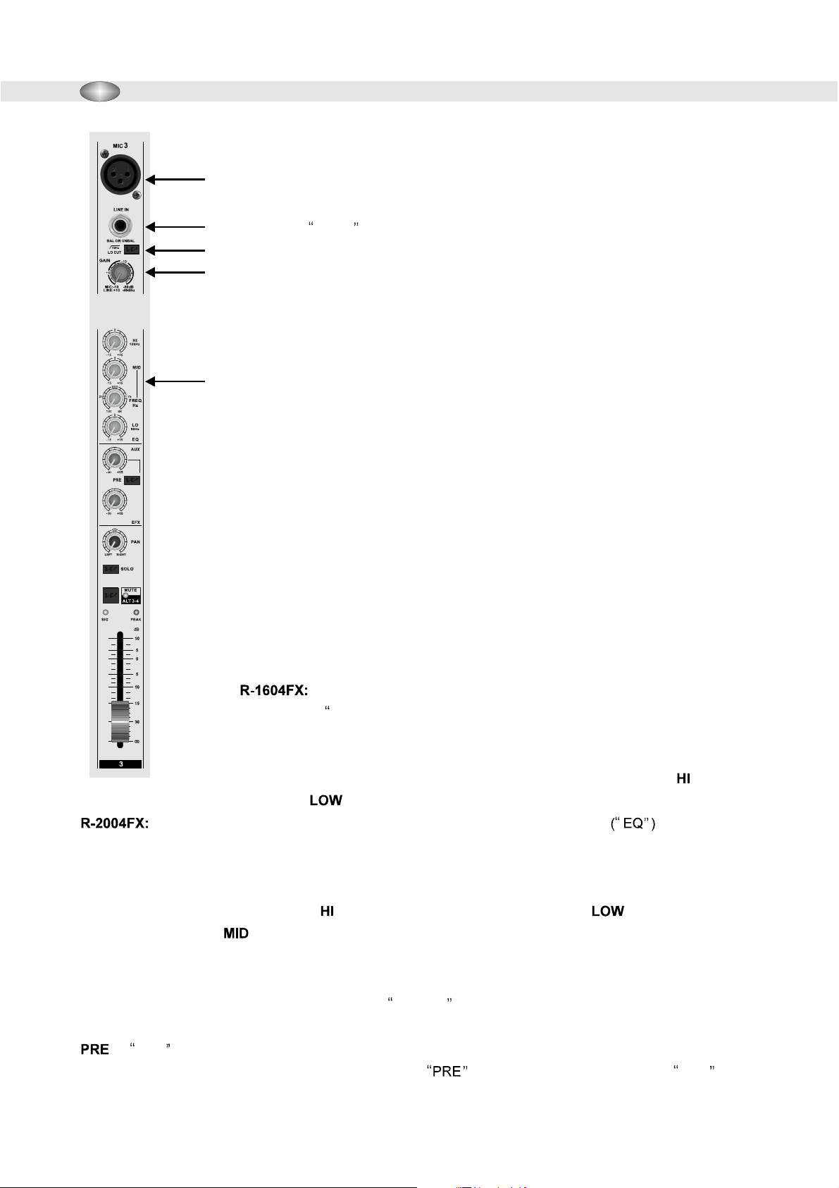
1. Low Impedance (Low Z) Mic Input jacks:
2
headroom Low Z mic inputs are for use with balanced, low impedance
microphones.
3
4
2. Line Input jacks:
be connected to (-10 to +4dBu) balanced or unbalanced line level sources.
3. Low Cut Filter:
When activated, this filter provides an 18dB per octave roll off with -3dB at 75Hz
and can be used to reduce mic handling noise, wind and popping when
5
microphones are used. It is also useful for minimizing excessive low frequency line
level signals.
4. Gain Control:
dynamic range, the input preamp level of each Mic channel is controlled by the
Gain Control on each channel. To set the Gain Control, place the desired channel
in SOLO mode and watch the left LED bar-graph meter in the Master section of the
mixer while the signal source for that channel is active (whether it be a singer using
a microphone or an instrument connected to the LINE INPUT of the channel). The
ideal level is between 0dB an d +3dB. If the PEAK LED on the channel lights up
consistently, the Gain Control is set too high. It is acceptable for the PEAK LED to
flash periodically, especially with instruments like drums or level peaks during loud
portions of a performance.
These Tip, Ring, Sleeve (TRS) jacks are designed to
The Low Cut Filter is activated by engaging this button.
In order to achieve the best signal to noise ratio and adequate
,,
1
4
/
The low noise, high
5. EQ Section
Each mono channel on the R-1604FX features a three band
Equalization ( EQ,,) section. Each band allows for up to 15 decibels of boost
(increase) or cut (decrease) of the signal in the tone range for which it controls (HI,
MID, LOW). In the center position, the equalizer is bypassed (FLAT) and
the control has no effect on the tonal characteristics of the signal. The EQ
control is centered at 12kHz and the EQ control is centered at 80Hz.
Each mono channel on the R-2004FX features a three band Equalization section along
with a sweepable mid-band control. Each band allows for up to 15 decibels of boost (increase) or cut
(decrease) of the signal in the tone range for which it controls (HI, MID, LOW). In the center
position of the knob, for each band, the equalizer is bypassed (FLAT) and the control has no effect on the
tonal characteristics of the signal. The EQ control is centered at 12kHz and the EQ control is
centered at 80Hz. The band control is slightly different in that it has two knobs. One knob controls the
center frequency (100Hz to 8kHz) and the other knob controls the amount of boost or cut for the selected
frequency.
AUX SECTION:
(labeled PRE) and post-fader (labeled POST).
: A PRE fader aux derives its signal independent from the channel fader. Any changes made on the
channel fader do not affect the signal that is sent to the AUX buss (output). This type of AUX is
commonly used for a stage monitor mix in sound reinforcement applications. It could also be used as a
headphone mix in a recording application.
There are two types of AUX ( Auxiliary ) available on the R Series mixers. Pre-fader
detented
detented
Page 5
R Series Mixers R-1604FX & R-2004FX
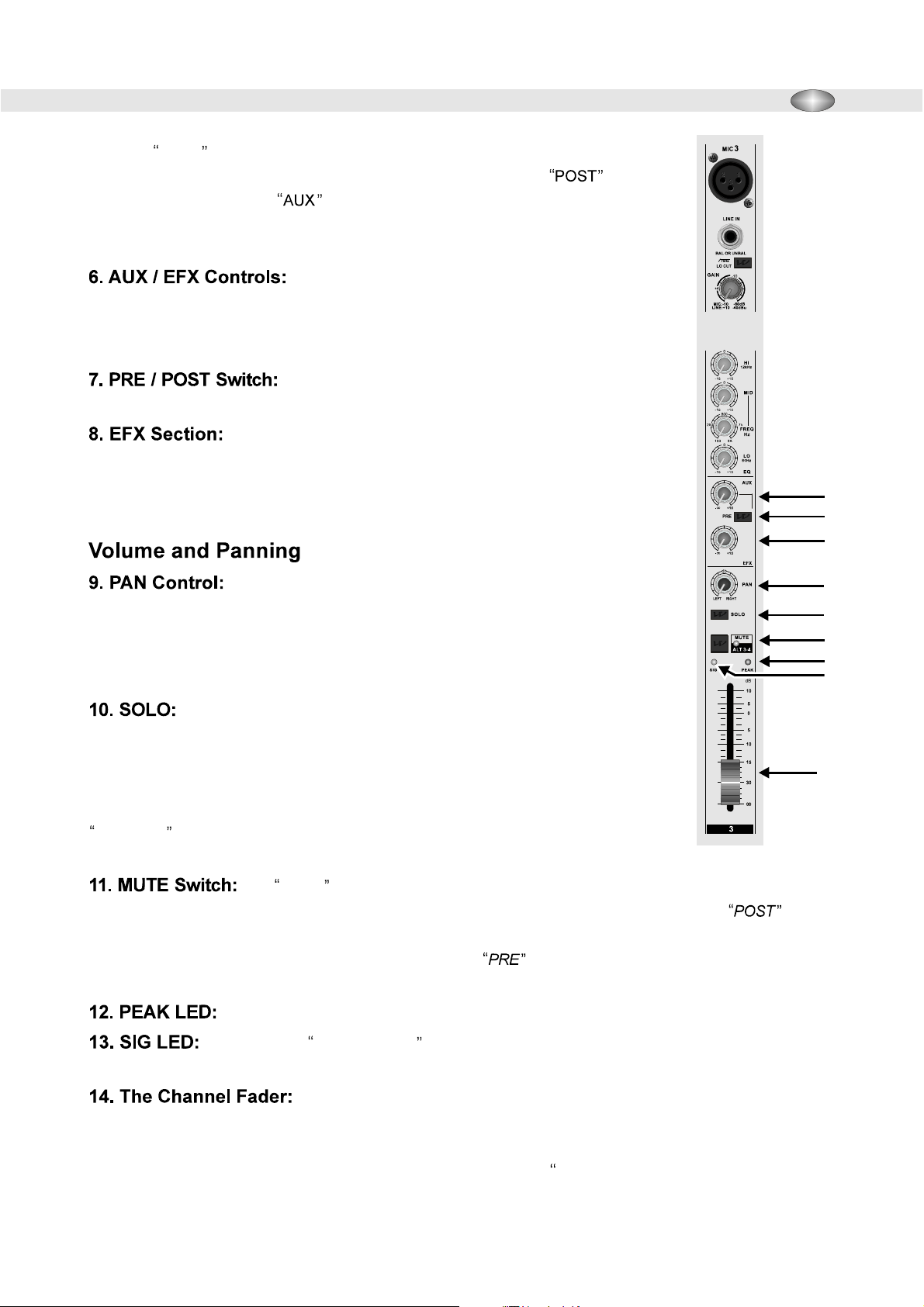
POST: A POST fader aux derives its signal after the channel fader. Any changes
made on the channel fader affect the signal level that is sent to the AUX
buss (output). This type of is commonly used to supply audio signals to an
effects processor such as a reverb or a delay in both sound reinforcement and
recording applications.
Each AUX control is mono and post EQ. Any changes
made to the equalizer section of a channel will affect the AUX / EFX signals as well
as the MAIN output signals. There is 15 dB of gain available for each AUX / EFX
SEND knob.
With this switch, it is possible to change AUX 1 to either
PRE or POST fader mode.
Each EFX control is post-fader. Any changes made to the
channel fader will also result in a change of level of the signal being sent to the EFX
buss (output).
.4.
6
7
8
On the mono channels, the PAN control adjusts the balance of
the signal being sent to the left and right MAIN MIX (or ALT 3-4, if a channel is
muted). Turning the PAN control fully left on a stereo channel will cause the right
input,s signal level to decrease. Turning the PAN control fully right on a stereo
channel will cause the left input,s signal level to decrease.
Engaging a channel,s SOLO button allows for monitoring the input signal
of that channel (as well as any other channels that are in SOLO mode) through the
Headphone and Control Room outputs, as well as being able to see that signal level in
the left LED bar-graph meter. When any channel is in SOLO mode, the meter will only
display the levels of the channel(s) that have their SOLO button(s) engaged. The
SOLO ON LED lights up (located just below the LED bar-graph meters) when any
SOLO buttons are engaged.
The MUTE switch, on each channel, allows for muting of the channel,s signal from the
MAIN MIX buss and also reroutes the signal to the ALT 3-4 output when it is engaged. The AUX mode
and EFX send busses (outputs) are affected by an engaged MUTE button and the signal is removed from those
busses when a channel (or channels) are muted. The AUX buss is not affected by an engaged MUTE
button.
The PEAK LED lights up when the input signal is driven too high in level.
9
10
11
12
13
14
The SIG LED ( Signal Present ) will light up when a minimal signal level of -20dBu is
present at the input of a channel.
The fader allows for control of the level of the signal that is being sent to the
MAIN MIX fader, or the ALT 3-4 master fader, if the channel is muted. When the fader is set at the 0dB
position, the signal is not being increased or decreased from the level that has been set with the Gain
Control. Adjust the level of each fader to acquire the best sounding mix,,of the balance of signals from
each input.
Page 6

.5.
Stereo Input Channel:
R-1604FX & R-2004FX R Series Mixers
The stereo channels on the R-1604FX and the R-2004FX feature two ,
,,
line level inputs with Tip / Sleeve (TS) jacks for left and right input signals. These
1
4
/
unbalanced
inputs can accommodate both stereo and mono inputs. When using a mono source,
connect the cable t o the LEFT input only and the channel PAN control will operate
like the other mono channels on the mixer.
Each stereo channel features a three band EQ section. The HI,control is centered
at 12kHz, the MID,control is centered at 2.5kHz and the LOW,control is centered at
80Hz. With a stereo source signal, the AUX / EFX controls operate the same as the
mono channels except they sum,,the stereo signal and it becomes a mono signal
on the AUX / EFX busses (outputs). This has no affect on the stereo signal being
sent to the MAIN MIX / ALT 3-4 busses.
,,
15 / 16. Stereo Inputs:
15
17
16
Left / Mono Input:
1
4
/
17. Level Button:
Master Section
AUX EFX Send
18. AUX EFX Control:
19. AUX EFX Send Jacks:
,,
1
/
4
Stereo EFX Returns
20. EFX Return Jacks:
Page 7

R Series Mixers R-1604FX & R-2004FX
.6.
21. EFX to MAIN / AUX:
22. Internal EFFECT Preset Select Knob:
effect. The level of t
he chosen effect is controlled by the EFX RETURN knobs explained in #20 and #21. The
Level controls for the EFX Return Jacks as described in #20.
This knob allows the selection of the desired digital
signal from the digital effects unit is disabled when a cable is connected to the EFX Return Jacks.
LIST OF AVAILABLE EFFECT
S
DELAY 1 CHORUS 2
DELAY 2 CHORUS 3
ROOM 1 PLATE REVERB 1
ROOM 2 PLATE REVERB 2
ROOM 3 PLATE REVERB 3
HALL 1 ROTARY SPEAKER
HALL 2 FLANGE
CHORUS 1 BYPASS
23. EFFECT OFF / ON:
Engages and disengages the digital
18
effects signal.
METERING
24. Level Meter:
SOLO mode is displayed on the 10 segment LED bar-graph
The signal level of the MAIN MIX and
22
23
meters. In SOLO mode, only the left meter will display the signal.
This meter is also used for setting the correct gain structure of
the mono input channels as described in item #4.
21
25. SOLO ON LED:
This LED lights up to indicate when any
channel SOLO button is engaged.
28
26
27
+12
+6
+3
0
-3
-6
-9
-12
-18
-24
24
25
26. Power ON LED:
This LED lights when the power is on
for the mixer.
27. Phantom Power Switch:
When engaged, this switch
applies 48Volts DC to all of the microphone inputs to allow the use
of condenser microphones. This switch should remain turned off
when only using dynamic type microphones. Bring the MAIN
,,
MIX faders all the way down when turning this switch on and off.
28. Phantom Power LED:
This LED lights when the
Phantom Power switch is on.
2 Track Output
29. 2 Track Output:
29
1920
Page 8

.7.
R-1604FX & R-2004FX R Series Mixers
30. 2 Track to Mix button:
the MAIN MIX. The playback volume is controlled by the 2TK LEVEL knob (#39).
31. 2 Track to Control Room / Phones:
Engaging this button allows the routing of the 2 Track Input (TAPE IN) to
,,
Engaging this button allows the routing of the
2 Track Input (TAPE IN) to the CONTROL ROOM / PHONES section. The playback volume is controlled by
the 2TK LEVEL knob (#39).
32
,,
32. Control Room Output Jacks:
The Control Room
outputs are designed to be connected to studio monitor
speakers for monitoring the recording process. This output
derives its selectable source signal from the either the MAIN
40
MIX, ALT 3-4, anything that is in SOLO mode or the 2TRK
input (TAPE IN). These outputs can also be used for a live
33
recording send.
33. Headphones:
,,
This is a standard Tip-Ring-Sleeve
1
/
4
(TRS) amplified stereo headphone output jack.
34. Control Room Level Control:
+12
+6
+3
0
-3
-6
-9
-12
-18
-24
the level of both the stereo Control Room and Phones outputs.
35. MAIN MIX, ALT 3-4 switch:
for the monitoring of the MAIN MIX or the ALT 3-4 stereo
busses through the Control Room / Phones section.
This knob controls
These switches allow
34
31
35
37
39
38
30
36
36. Main Mix Faders:
These two faders control the
overall Left / Right stereo mix to the MAIN OUTPUT jacks.
37. ALT 3-4 Fader:
This single stereo fader adjusts the
overall level of anything assigned to the ALT 3-4 buss. (Any
channel that is in MUTE mode).
ALT 3-4 TO MIX:
When this button is engaged,
signals assigned to the ALT 3-4 buss (any channel that is in
MUTE mode) will be routed to the MAIN MIX buss (outputs).
39. 2TK LEVEL:
This knob controls the playback level of
the signal coming into the 2 Track Input (TAPE IN).
40. Effect Foot Switch:
This jack allows for the remote
on / off switching of the digital effects unit. A normally-
,,
open , latching footswitch is required.
Page 9

R Series Mixers R-1604FX & R-2004FX
Rear Panel R-1604FX / R-2004FX
.8.
41. Channel Insert Jacks (R-2004FX only):
equipped with Channel Insert jacks. These jacks are wired pre-fader, post EQ and pre Aux Send. The Insert
jacks provide a method of routing a channel's signal through a external serial effects device (such as a gate
or a compressor or even several serial processing devices connected to each other) and return that
processed signal back to the mixer channel. These insert jacks can also be used as post EQ direct outputs
for recording or other external signal routing. Special cables are required to accomplish some of these
configurations. Refer to the CONNECTIONS portion of this manual for more details.
42. MAIN XLR Outputs:
Pin 1 = ground, Pin 2 = hot (+) and Pin 3 = cold (-).
43. ALT 3-4 Outputs:
Tip = hot (+), Ring = cold (-), Sleeve = ground.
Left and Right balanced XLR output connections wired with:
,,
Balanced Tip-Ring-Sleeve (TRS) wired with:
1
4
/
All mono input channels on the R-2004FX are
44. AC Power Cable Connector
45. Power Switch - On / Off
Rear Panel 2004FX
Rear Panel R-1604FX
44
45
424544
43 41
42
43
Page 10

.9.
R-1604FX & R-2004FX R Series Mixers
Connections
,,
The R Series mixers use 3 different types of audio connectors: 3 pin XLR, phone jacks and RCA phono
jacks. Some of these connections are balanced (3 conductor), unbalanced
(2 conductor), and some are stereo or have other multiple functions.
1
/
4
Microphone Inputs
All microphone (mic) jacks are female XLR connectors
wired balanced with:
Pin 1 = ground, Pin 2 = hot (+) and Pin 3 = cold (-).
It is not recommended to use unbalanced microphone
connections especially if Phantom Power is on. This
could damage the mixer and the microphones.
ALT 3-4 Outputs
,,
The ALT 3-4 outputs are wired with Tip Ring Sleeve
1
4
/
jacks and are wired balanced with:
,,
1
- Tip = hot (+), Ring = cold (-), Sleeve = ground.
4
/
Insert Jacks
,,
1
The Channel Insert Jacks are wired with Tip Ring
Sleeve jacks and are wired unbalanced with:
,,
1
4
- Tip = Return (+), Ring = Send (+), Sleeve = ground
/
(-). These jacks can also be used as direct outputs for
direct-to-multi-track recording.
4
/
1. Ground / Shield
Headphones
Ring
Tip
Balanced Mic XLR
Left Signal
Right Signal
Ground
Sleeve
Balanced Unbalanced
Hot (+) Tip
Cold (-) Ring
Ground /
Shield / Sleeve
2. Hot (+)
3. Cold (-)
Inserts
Ring
Tip
Signal
Ground / Shield / Sleeve
Signal return
Signal send
Ground / Shield /
Sleeve
Sleeve
+ lead to Tip
Stereo 2 Track Inputs and Outputs
- To Ring
Sleeve
(TAPE IN / TAPE OUT)
The Stereo 2 Track Inputs and Outputs (TAPE IN / TAPE
OUT) are wired with RCA phono plugs and are wired
unbalanced with:
Tip = hot (+), Sleeve = ground (-).
Headphone Output
,,
The Headphone output is wired with Tip Ring Sleeve jack and is wired as follows:
,,
1
4
- Tip = Left, Ring = Right, Sleeve = ground.
/
1
4
/
+ lead t o Tip
- lead and Shield to
Sleeve (Ground)
Page 11

R Series Mixers R-1604FX & R-2004FX
BLOCK DIAGRAM R-1604FX
.10.
Page 12

.11.
R-1604FX & R-2004FX R Series Mixers
BLOCK DIAGRAM R-2004FX
Page 13

R Series Mixers R-1604FX & R-2004FX
.12.
SPECIFICATIONS - R-1604FX / R-2004FX
Maximum Output Level
(0.5% T.H.D at 1kHz)
Total Harmonic Distortion
Frequency Response
Hum and Noise
(Average, Rs=150 )
Maximum Voltage Gain
+22dB(MIXL/R,ALT3~4) @600 ohm
+22dB(AUX. EFX SEND) @600
+22dB(INSERT) @40 k
+22dB(CTRL ROOM) @600
Over 130mw (Headphone) @40
0.0025% @+14dB 20Hz~20kHz
(MIXL/R, AUX, EFX, CTRL ROOM) @600 ohm
20Hz~ 20kHz, +0 / -1dB
(MIXL/R, AUX, SEND, CTRL ROOM) @600 ohm
-127dB Equivalent Input Noise
-95dB Residual Noise(MIXL/R,ALT3-4, AUX. CTRL ROOM)
-90dB(MIXL/R,ALT3-4,AUX. SEND, CTRL ROOM)
Master Fader at Nominal Level and all Channel Assign Switch of
72dB MIC IN TO MIXL/R,ALT3-4
72dB MIC IN TO AUX EFX SEND
74dB MIC IN TO CONTROL ROOML/R
72dB MIC IN TO RECL/R
54dB LINE IN TO MIXL/R,ALT3-4
58dB LINE IN TO AUX EFX SEND
58dB LINE IN TO AUX ,
65dB LINE IN TO CONTROL ROOML/R
22dB ST IN TO MIXL/R,ALT3-4
20dB EFX RETURNL/RINTOMIXL/R
16dB TAPE IN TO MIXL/R
ALT 3-4,
ALT 3-4, EFX
*0dB=0.775Vrms, 0dBV=1Vrms
ohm
ohm
ohm
ohm
EFX
EFX
EFX
Maximum Levels
Interference (Crosstalk) at 1kHZ
Mono Input Channel Gain
Input Channel EQ (R-1604FX)
Input channel EQ (R-2004FX)
Peak Indicator
Level Meters
Phantom Power
Effects Preset
Mic in: +4dBu
Tape in: +13dBu
All other inputs: +25dBu
Main Fader Down: -85dBu
Channel Alt / Mute Switch Engaged: -80dBu
Channel Fader Down: -70dBu
50dB variable(-60dB ~ -10dB), (-40dB ~ +10dB)
(+ / -15dB)
HIGH: 12kHz Shelving
MID: (+ / -15dB) 2.5kHz Shelving
(+ / -15dB)
LOW: 80Hz Shelving
HIGH: (+ / -15dB) 12kHz Shelving
MID: (+ / -15dB) 100-8kHz (EQ for Frequency Variable) Peaking
LOW: (+ / -15dB) 80Hz Shelving
Input Channel: Turns on 3dB Under Pre-fader Signal Clip
10- Segment LED (Output of +4dB at 0dB) MainL/R
48V
(1) Delay 1 (2) Delay 2
(3) Room 1 (4) Room 2 (5) Room 3
(6) Hall 1 (7) Hall 2
(8) Chorus 1 (9) (10)
(11) (12) (13)
Plate Reverb 1 Plate Reverb 2 Plate reverb 3
(14 (15) (16)
) Rotary speaker Flange Bypass
Chorus 2 Chorus 3
Weights
Dimensions(HxWxD-mm/inches)
R-1604FX: 6kg, 13.2 lbs
R-2004FX: 7.5kg, 16.5 lbs
R-1604FX: x x
R-2004FX: x 418.8mm x
81.6mm 309mm 346mm
,, ,,
3.2 x
81.6mm 399.7mm
3.2 x 16.5 x 15.7
,,
12.1 x 13.6
,, ,, ,,
Page 14

.13.
Input Connector Input Impedance Regular Impedance Regular Input Level Connector Type
R-1604FX & R-2004FX R Series Mixers
Channel Mic 3k 50~600 -60dB XLR
Channel Line 20k 600 -30dB Phone Jack (TRS)
Stereo Input 10k 600 -20dB Unbalanced
Effect Return 10k 600 +4dB Unbalanced
Mono Channel Insert Input 10k 600 odB Phone Jack (TRS)
Tape In 10k 600 -10dBV RCA
Output Connector Output Impedance Regular Impedance Rated Output Level Connector Type
MIX OutL/R 120 600 +4dB XLR Balanced
ohm ohm Balanced
ohm ohm
ohm ohm
Phone Jack
ohm ohm
Phone Jack
ohm ohm
ohm ohm
ohm ohm
CTRL Room Output 100 600 +4dB Unbalanced
Aux EFX send 100 600 +4dB Unbalanced
Mono Channel Insert Output 600 10k 0dB Phone Jack (TRS)
Rec Output 600 10k -10dBV RCA
Headphone Output 100 40 3mw Stereo Phone Jack
ohm ohm
Phone Jack
ohm ohm
Phone Jack
ohm ohm
ohm ohm
ohm ohm
Page 15

Wharfedale Professional
IAG House, Sovereign Court, Ermine Business Park, Huntingdon, PE29 6XU
www.wharfedalepro.com
 Loading...