

Page 1
R 1604/2004 OPERATING MANUAL
Page 2

.1.
R1604 & R2004 R Series Mixers
Introduction
Thank you for purchasing an R1604/2004 Mixer from Wharfedale Professional. Please read these
instructions carefully to ensure problem free operation and user satisfaction.The R Series of mixers from
Wharfedale Professional are designed to offer a superior quality audio performance in an easy to use, great
value package. The quality of the R Series is such it can be used in a variety of professional applications
such as studio, sound reinforcement, field recording and film/video production.
Features R1604/2004:
* 4(R1604)/8(R2004) balanced/unbalanced mono line input
* 4(R1604)/8(R2004) low noise, high headroom XLR mic inputs
* 4 pairs of balanced/unbalanced stereo line inputs with +4/-10 input
gain/sensitivity selector
* Insert facility on all mono channels (R2004 only)
* 48V DC global phantom power
* 3- band EQs with semi-parametric mids in all mono input channels (R2004 only)
* 3- band EQs in all input channels (12kHz, 2.5kHz, 80Hz)
* 75Hz, 18dB/octave low cut filter on mono input channels
* PFL/SOLO and Mute/ALT 3-4 on all channels
* ALT 3-4 extra stereo bus
* 2 stereo EFX returns
* EFX to Main, ALT 3-4 and AUX 1 switch
* Balanced inputs and outputs
* Peak and signal LEDs on mono channel
* Two AUX send (Pre and Post fader switch on AUX 1)
* Separate main mix, ALT3-4, control room and headphone outputs
* 2 track inputs assignable to main mix, control room/headphone outputs
* Highly accurate 10 segment bargraph meters
* High quality 60mm faders
,,
* 19 Rack Mounting kit included
Page 3

R Series Mixers R1604 & R2004
Getting Started
1. Power Supply
The R Series mixer is supplied with an external power supply unit. Only use the power supply provided
with your mixer. Connect the R Series mixer to the power supply unit and THEN connect the power
supply unit to the Mains. During long periods of operation the mixer may become warm. Therefore it is
important that the unit is placed where the air is able to flow freely around it. The power supply is factory
set to the correct voltage and this can be checked by referring to the label on the unit. If the mixer is used
in a country having a different supply voltage then a new power supply will be required and you should
consult your dealer.
2. Packing
Every care has been taken to ensure that your mixer reaches you in perfect condition and working order.
The exterior and internal packaging has been designed to protect the unit in transit, but should you notice
any damage to the unit, please notify the place of purchase immediately.
.2.
3. Safety
Avoid the excessive heat, humidity, dust and vibration: Keep the unit away from locations
where it is likely to be exposed to high temperature or humidity, such as near radiators, stoves, etc. Also
avoid locations which are subjected to excessive dust accumulation, or to vibration that could cause
mechanical damage.
Avoid physical shocks: Strong physical shocks to the unit may cause damage. Handle the unit
with care.
Do not open the case to attempt to repairs or modifications yourself: This product
contains no user-serviceable parts. Refer all maintenance to qualified service personnel.
Always power off before making connections: Always turn the AC mains OFF before
connecting cables. This is important to prevent damage to the unit itself as well as other connected
equipment.
4. Warranty
The R Series mixers warranty covers any defects in the manufacture of the product for a period of 12
months from the date of purchase. The Warranty is non-transferable and applies to the original purchaser
only. Should you have any Warranty issues, please contact your place of purchase who will advise on a
returns procedure.
Page 4
.3.
R1604 & R2004 R Series Mixers
Features of the R Series Mixer
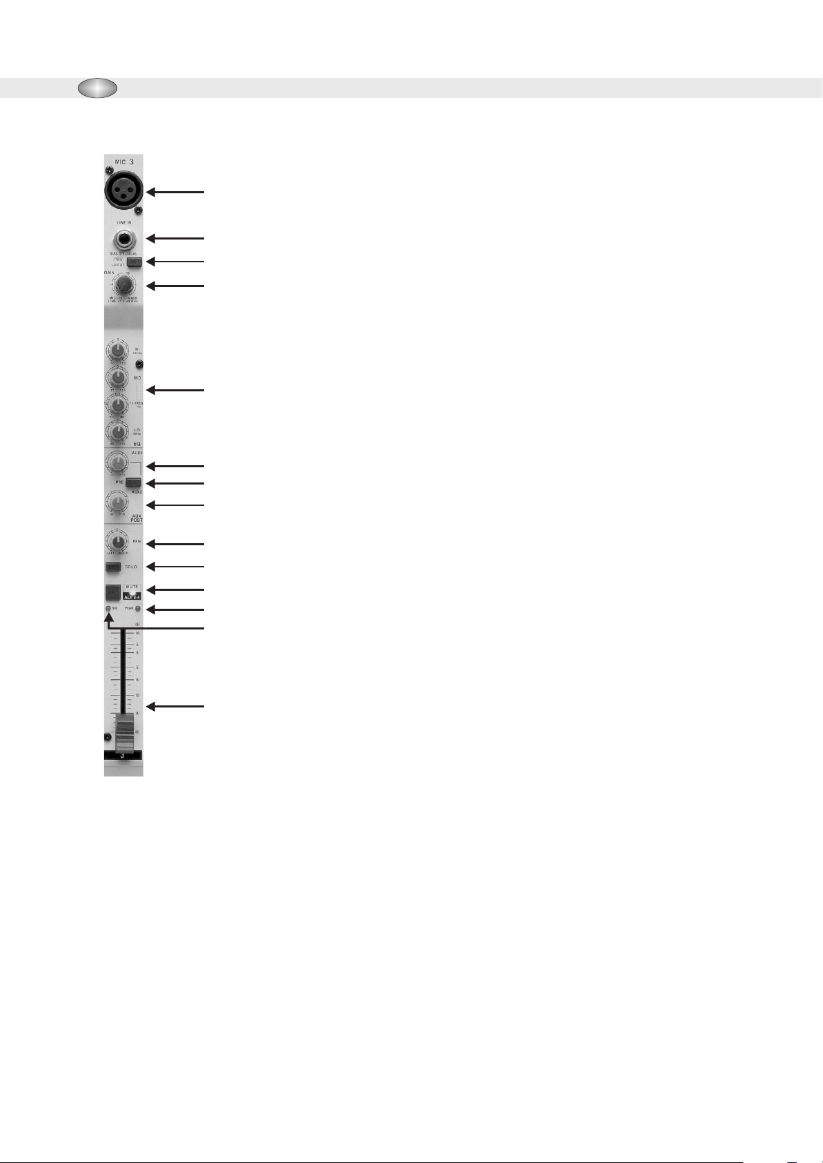
Mono Input Channels:
1
1. Low Impedance (or Low Z) Mic Inputs
2
3
4
5
6
7
8
9
10
11
12
13
The low noise, high headroom Low Z mic inputs for use with balanced or
low impedance microphones or low level external equipment with XLR
connectors.
2. Line Inputs
The features of balanced/unbalanced high impedance mono line inputs for
use with high level signals with1/4 phone plug connectors.
3. Low Cut Filter
The low cut filter can be activated by pressing this button. The slope of this
filter is 18dB/oct., -3dB at 75Hz and should be used when it is necessary to
eliminate or reduce background rumble, breathing noises and popping.
4. Gain Control
The input level on the Mic channels is controlled by using the Gain Control
to achieve the best signal to noise ratio and dynamic range. The Gain
control should be used in conjunction with the Peak LED which will
illuminate if the input gain is too high. The gain circuit has a wide range
from -10dB to -60dB.
5. EQ Section:
R2004: Each mono input channel features a three band EQ section with
,,
semi-parametric mid bands. All bands provide boosts or cut of up to 15dB.
In the center position, the equalizer is off (FLAT). The Hi EQ control has
14
R1604: Each mono input channel feature a three band EQ section. The Hi EQ control has an upper shelf
limit of 12kHz, the Mid EQ 2.5kHz and the Low EQ 80 Hz. Each control has a range of -15dB to +15dB cut
and boost.
* The EQ control section should be used in conjunction with the Low Cut Filter (3) to add extra
warmth or extra punch to the mix where necessary.
an upper shelf limit of 12kHz and the Low EQ at 80Hz. For the Mid range,
the console features a semi-parametric equalizer with a filter quality (Q) of 1
octave, tunable from 100Hz to 8kHz. Use the Mid control to set the amount
of boost or cut, and the FREQUENCY control to determine the central
frequency.
AUX Section: There are two types of auxiliary: PRE FADER and POST FADER.
A PRE FADER auxiliary occurs in the signal path before the main channel fader, and therefore the amount of
signal going down the auxiliary is only affect by the auxiliary level control. Any change in the main fader level
will not affect the amount of signal going down the auxiliary. This type of auxiliary is often used for a monitor
mix when the levels need to be independent of the main mix.
Page 5

R Series Mixers R1604 & R2004
A POST FADER auxiliary occurs in the signal chain after channel fader. This type of auxiliary is normally
used to send to an effects unit, such as a reverb, where the level of reverb needs to follow the level of the
main fader.
6. AUX 1 Control: The Aux Send is mono and Post EQ. This controls the amount of signal being sent down
AUX 1, and ranges from -Infinity dB to +15dB.
7. PRE/POST Switch: The AUX 1 could slect pre or post fader for monitors, effects or separately balanced
feeds for recording and broadcast. Signals being sent to an effect unit can be return to mixer via the EFX
Returns found on the top panel of the mixer.
8. AUX 2 Control: Aux 2 is set to post fader whicn allows you adjust channel send level to external devices
such as effect units or additional headphone/monitor system, and ranges from -Infinity dB to +15dB.
.4.
Volume and Panning
9. PAN Control: The Pan control adjusts the amount of channel signal sent to the left versus the right inputs.
On the mono channels the controls act as true Pan pots. When working with subgroups (ALT 3-4), you
can use PAN control to assign the signal to just one output, which gives you additional flexibility in
recording situations.
10. SOLO: The solo button allows you to meter and listen to an individual channel in isolation from other
channels. When pressed, the channel signal is sent to the headphone/control room output whilst signals
from the Main Outputs and any channels not SOLO d, are also disconnected from the headphone output.
All non SOLO d signals are also disconnected from the Main Output Meters, and these meters now
become the SOLO Meter for any SOLO d channels. The SOLO is PFL (Pre-Fader Listen) and therefore
the signal you are hearing and metering occurs before the main channel fader. Using the SOLO Button in
conjunction with Gain Level control is the best way to ensure that the signal is coming into the channel at
correct level. After pressing the SOLO Button the input gain should be adjusted so that the highest peaks
of the signal are metering at between 0 dB and +3 dB. This should be done individually for each channel.
Press the SOLO button does not affect the Main Outputs/ALT3-4 and therefore you can use this feature
to check what is coming into a channel, leaving the Main Mix undisturbed. When in operation the SOLO
ON (25) light in the Master Section will be lit.
11. MUTE Switch: The MUTE switch cuts the signal coming down the pre- fader, hence muting that channel
in the Main Mix and the input signal will be routed to the ALT 3-4 output instead of the Main Mix. The aux
send 1 & 2 which are set to post-fader are likewise muted for the channel, while the AUX 1 pre-fader
monitor path remain active (switch on) irrespective of whether the channel is muted or not.
12. Peak LED: The PEAK LED lights up when the input signal is driven too high.
13. Signal Present LED: The LED will light when the channel signal exceeds -20dBu.
,
,
,
14. The Channel Fader: The fader allows you to control the amount of channel signal being sent to the Left
and Right Main/ALT3-4 Outputs. The amount of signal ranges should from, -infinity dB (no signal) to +10
dB (maximum signal). When in 0 dB position there is no boosting or cutting of the signal coming down
the channel, and this give the optimum signal to noise ratio. To get best results it is important to set the
Input gain level correctly.
Page 6

.5.
16
17
15
R1604 & R2004 R Series Mixers
Stereo Input Channel
The R1604/2004 stereo channel features two unbalanced line level
inputs with 1/4 jacks for left and right signals. These inputs can be
used as both Stereo and Mono inputs. When using them with a
mono source then the left input should be used. The stereo input
channels are designed for use with any line level sources such as
CD players and EFX units. Each stereo input channel features a
three band EQ section, the Hi EQ control has an upper shelf limit of
12kHz, the Mid EQ 2.5kHz and the Low EQ 80Hz. The AUX sends
are the same as for mono channels.
15. Stereo Input: Left and Right Input sockets.
16. Left (Mono) Input: When the left input is connected only, then the
Channel operates in mono.
,,
17. The Level button: This button lets you choose between the two
standard operating level -10dBV and +4dBu. It is important to check the
incoming device s operating level and choose the appropriate level on
The channel Input.
,
Page 7

R Series Mixers R1604 & R2004
Master Section
AUX sends
18. AUX 1 & 2 Control: The AUX1,2 master VR provide
over all level control of AUX send.
19. AUX Send Jacks: These unbalanced 1/4 jacks are
AUX1 and AUX 2 outputs.
,,
.6.
33
28
Stereo EFX Returns
20. EFX Return Jacks
There are two additional Stereo AUX returns on the
R1604/2004. The EFX Return act as mini Input
Channels and are used to bring signals from Effect Unit
back to the mixer via the EFX Return inputs on the top
panel. When using an Effect Unit with stereo outputs the
left and right EFX Return inputs can be used to keep the
stereo effect. The outputs of the Effect Unit should be
plugged into the corresponding left and right EFX Return
nputs. If you wish to use an EFX Return in MONO then
only the left inputs should be used. This mono signal is
then switched to be sent equally to the left and right Main
outputs. Both EFX Return 1 and EFX Return 2 signal are
assigned to the Main mix, press the EFX TO AUX1(22)
button can route the EFX Return 1 signal to the AUX 1
bus. Press EFX to ALT3-4 (23) button can route the EFX
Return 2 signal to the ALT3-4 output.
21
22
23
18
34
35
38
37
27
26
24
25
31
30
36
21. The EFX Returns levels are operated by these controls.
22. EFX to AUX button. (EFX Return 1)
23. EFX to ALT 3-4. (EFX Return 2)
19 29
Metering
24. Level Meter
The level of the Main Mix/Solo is displayed on these 10
segment bargraph meters. When any channels Are
,
SOLO d the Left meter act as the SOLO meter, and are
used to set the correct Input Gain into a channel. If the
signal levels are too high, distortion may result, and if they are too low then unwanted noise will present.
20 32
Page 8

.7.
25. The SOLO ON indicator
This LED lights up when any of the channels are SOLO d, indicating that the Left meter are now
functioning as SOLO meter.
26. Power ON LED: This LED is illuminated when Power is ON.
27. Phantom Power switch: Press this switch applies 48 volt phantom power to all the microphone inputs.
Phantom power should be turned off when not required, and must never be used with an unbalanced
microphone. Do not operate this switch with the fader up, as a loud click will result.
28. Phantom Power LED: When this LED is illuminated it indicates that the +48 V DC Phantom Power is
present.
R1604 & R2004 R Series Mixers
,
2Track In/Out
29. 2 Track Input: The two track input section has RCA jack inputs to enable easy connection to a DAT tape
devices, or a cassette and other audio equipment. This is used primarily for listening to mix playback
from a tape for example.
30. 2 TK to MIX: Press this button allows you to monitor the output from the two track tape machine
connected to the Stereo 2 Track inputs. The signal from the tape is fed in to the Main mix.
31. 2 TK to CONTROL ROOM AND PHONES: Press this button allows you to monitor the output from the
two track tape machine connected to the Stereo 2 Track inputs. The signal from the tape is fed in to the
CONTROL ROOM and PHONES.
Control Room/Phones
32. Control Room Output Jacks: The control room output is normally connected to the monitoring system
in the control room and carries the stereo MAIN mix or, when selected, the SOLO signals.
33. Headphones: This is unbalanced on a 1/4 stereo jack. Cables connected to this output should be
wired with TIP left signal, RING right signal, and SLEEVE to ground. Use only stereo headphones! Use
mono headphones may cause damage!
34. Control Room Level control: This knob controls the levels of both the stereo control room and phones
outputs.
35. MAIN MIX and ALT 3-4 switch: Press these buttons allow you to monitor the signal from the Main Mix or
ALT 3-4.
,,
Main and ALT 3-4 Level
36. Main Mix Faders: These control the overall level of any signals which have been sent to the stereo
left and right outputs on the back section.
37. ALT 3-4 fader: This fader controls the overall level of any signals which have been sent to the ALT 3-4.
38. ALT 3-4 TO MIX: Press this button allows you to send ALT 3-4 signal to the Main Mix outputs.
Page 9

R Series Mixers R1604 & R2004
.8.
Rear Panel R1604/2004
39. Inserts Point (R2004 only) The Channel Inserts:
All mono input channels of R2004 are equipped with inserts. They are pre-fader, post-EQ and pre-aux
send. The Insert Points are used to send the channel signal to processors (compressors, gate, EQ unit
etc.) and to bring the processed signal back into the channel. Insert Points use stereo 1/4 (TRS) jacks
with the Ring acting as a send to the processor, and the Tip acting as a return from the processor. They
can also be used to send to effect units, return the signal through the effect return points. Inserts can also
be used as post-EQ direct outputs, without interrupting the signal path. To this end, you will need a cable
fitted with mono phone plugs on the tape machine or effect device end, and a bridged stereo phone plug
on the console side (tip and ring shorted together).
40. Main XLR Outputs: Balanced XLR will be wired pin 1 ground/ pin 2 hot (positive), pin 3 cold (negative).
41. ALT 3-4 Outputs - Balanced TRS socket will be wired tip=signal, Ring=negative, sleeve =ground.
42. AC Power Cable Connector
43. Power Switch - On/Off
,,
Rear Panel 1604
42
43
Rear Panel 2004
40 41
404342
41 39
Page 10

.9.
R1604 & R2004 R Series Mixers
Connections
The R series use 3 different types of connectors: 3 pin XLR, 1/4 jacks, and phone plugs. Some of these are
balanced, some unbalanced, some are stereo and some have dual functions. These connectors are used in
various ways as dhow in the following.
Microphone Inputs, Main Mix & ALT 3-4 Outputs
These are balanced on female XLR connectors and connected as shown. Cables connected to any
microphone sockets should be wired with pin 1 ground, pin 2 hot(+ve) and pin 3 to cold(-ve). Use high quality
shield pair cable or multicore with individually shield pairs.
Line Inputs
These are balanced on 1/4 stereo type (TRS) jacks. Cable connected to any of these should use a stereo
jack wired with TIP hot(+ve), RING cold(-ve) and SLEEVE to ground.
,,
Insert Points
All of the insert points have both SEND and RETURN signals on a single 1/4 stereo jack. Cables connected
to any insert point should use a stereo jack wired with TIP return, RING send and SLEEVE to ground. Use
individually shield cable for both send and return or twin cable with individual screening on each core.
,,
,,
Auxiliary send, EFX return and Control Room Outputs
There are unbalanced on 1/4 jack. Cables connected to these inputs should use a mono jack wired with TIP
signal and SLEEVE to ground.
,,
Stereo 2 Track Inputs and Outputs
There are unbalanced on mono plugs. Cables connected to these should be wired PIN signal, and SLEVE to
ground.
Headphone Output
2. Hot (+ve)
3. Cold (-ve)
Left Signal
Right Signal
Ground
,,
Unbalanced Mic XLR
Inserts
2. Hot (+ve)
Link 3 to 1
Signal send
Signal return
Ground /
Screen
1. Screen
-ve lead to Ring
3 pole jack 2 pole jack
Balanced Unbalanced
Hot (+ve)
Cold (-ve)
Ground /
Screen
+ve lead to Tip
Sleeve
Signal
Ground /
Screen
+ve lead to Tip
-ve lead and
Sleeve to Ground
This is unbalanced on a 1/4 stereo jack. Cables connected to this output should be wired with TIP left signal,
RING right signal, and SLEEVE to ground
Balanced Mic XLR
1. Screen
Headphones
Ring
Tip
Sleeve
Page 11

R Series Mixers R1604 & R2004
.10.
BALANCED INPUT WIRING TO WHARFEDALE PRO UNIT WITH XLR CONNECTORS
BALANCED OUTPUT
2 1
Ground (earth)
3
BALANCED INPUT WIRING TO WHARFEDALE PRO UNIT WITH 1/4 JACK to XLR CONNECTORS
BALANCED OUTPUT
RING
TIP
SLEEVE
Ground (earth)
BALANCED INPUT WIRING TO WHARFEDALE PRO UNIT WITH STEREO 1/4 JACK to XLR CONNECTORS
BALANCED OUTPUT
RING
TIP
SLEEVE
Ground (earth) CABLE
BALANCED INPUT WIRING TO WHARFEDALE PRO UNIT WITH XLR CONNECTORS to STEREO 1/4 JACK
BALANCED OUTPUT
2 1
Ground (earth)
3
UNBALANCED INPUT AND OUTPUT WIRING WITH MONO 1/4 JACK CONNECTIONS
TIP
SLEEVE
Ground (earth) CABLE
BALANCED OUTPUT WIRING FROM WHARFEDALE PRO UNIT WITH XLR CONNECTORS TO BALANCED UNIT
OUTPUT from Wharfedale Pro unit
2 1
Ground (earth)
3
SIGNAL DIRECTION
CABLE
SIGNAL DIRECTION
CABLE
SIGNAL DIRECTION
SIGNAL DIRECTION
CABLE
SIGNAL DIRECTION
CABLE
Only connect ground if hum occurs
Only connect ground if hum occurs
Only connect ground if hum occurs
Only connect ground if hum occurs
Only connect ground if hum occurs
,,
,,
INPUT to Wharfedale Pro unit
INPUT to Wharfedale Pro unit
,,
INPUT to Wharfedale Pro unit
SLEEVE
INPUT to Wharfedale Pro unitSIGNAL DIRECTIONOUTPUT
INPUT SIGNAL DIRECTIONOUTPUT Wharfedale Pro unit
SLEEVE
TIP
RING
Wharfedale Pro unit
TIP
1 2
3
1 2
3
,,
INPUT to
SLEEVE
TIP
RING
BALANCED INPUT
1 2
3
A great deal of mis takes in sound
installations can be down to wrongly
wired audio connections. It is important
that the connections are correct to suit
your system.
An unbalanced audio system cable is
typically a s ingle conductor shielded with
the centre conductor relaying the signal
and the shield at ground.
Using a balanced audio system is where
a two conductor shielded cable has
each of the two center conductors
carrying the signal but of opposite
phase. This gives each conductor an
equal but inverted potential difference
from that of the ground. It is recommend
that you use a balanced microphone to
the mixer. This will eliminate interference
such as mains hum. If a non balanced
microphone is used do not use this
microphone at the same time as a
microphone requiring phantom power
'on' as this could cause damage to the
non balanced microphone.
For the best results whilst using
balanced line level inputs, common
grounding should be avoided. This
means not connecting the ground on
both the mixer input and output
connectors. Wharfedale Pro advise that
you connect the ground (shield) of the
input connecting cable to the ground of
the signal source while making sure the
ground (shield) is not connected to the
mixer's input connector. The output
cable connector from the mixer when
connecting to another balanced unit
input should have the ground (shield)
connected. This is the process by which
the ground (shield) is connected (tied) at
the source unit but is not connected to
the destination unit. If hum develops in
some instances the ground (shield) can
be connected on the input. Some
manufacturer have units that
recommend that the input connector
ground (shield) is tied and the output
disconnected. In this instance you may
need to connect the input connector
ground (shield) going to the input of the
mixer.
If an unbalanced system is used with
XLR connections please connect pin 3
to pin 1 (ground) of the connector. This
will mean that pin 2 transports the
positive (+ / hot) signal. If pin 1 and 3
are not connected this results in the
negative (- / cold) input being 'open'.
This will give an audible degradation of
the signal to noise ratio. This would
relate to both the input and output
connectors and involve the cable ground
(shield) connected at both.
Please note that some manufacturers
run their units with pin 2 (- / cold) and
pin 3 (+ / hot). This should be looked out
for and then the wiring could be modified
with labeled cables so that connections
of + / hot go to their corresponding +/
hot etc. Some manufacturers run their
unit with balanced inputs and
unbalanced outputs , therefore care
should be taken with the connections
when inserted into the system.
Unbalanced System
Balanced System
Page 12

.11.
BLOCK DIAGRAM R1604
R1604 & R2004 R Series Mixers
Page 13

R Series Mixers R1604 & R2004
BLOCK DIAGRAM R2004
.12.
Page 14

.13.
R1604 & R2004 R Series Mixers
*0dB=0.775Vrms, 0dBV=1Vrms
SPECIFICATIONS - R1604/R2004
Maximum Output Level +22dB(MIX L/ R, ALT 3~4)@600 ohm
(0.5% T.H.D at 1kHz) +22dB(AUX SEND1~2) @600 ohm
+22dB(INSERT) @40 k ohm
+22dB(CTRL RO O M) @600 ohm
Over 100mW(Headphone) @40 ohm
Total Harmonic Distortion 0.0025% @+14dB 20Hz~20kHz
(MIX L/ R, ALT 3-4, AUX SEND1~2, CTRL ROOM) @600 ohm
Frequency Response 20Hz~ 20kHz, +0/ -1dB
(MIX L/ R, ALT 3-4, AUX SEND1~2, CTRL ROOM) @600 ohm
Hum and Noise -127dB equivalent input noise
(Average, Rs=150 ) - 95dB residual noise(MIX L/ R, ALT 3-4, AUX SEND1~2, CTRL ROOM)
-90dB(MIX L/ R, ALT 3-4, AUX SEND1~2, CTRL ROOM)
* Master fader at nominal level and all channel assign switch OFF.
Maximum Voltage Gain 72dB MIC IN TO MIX L/ R, ALT3~4
72dB MIC IN TO AUX 1
72dB MIC IN TO AUX 2(POST), EFX
74dB MIC IN TO CONTROL ROO M L/ R
72dB MIC IN TO REC L/ R
54dB LINE IN TO MIX L/ R, ALT3~4
58dB LINE IN TO AUX 1
58dB LINE IN TO AUX 2(POST),
60dB LINE IN TO CONTROL ROOM L/ R
22dB ST IN TO MIX L/ R, ALT3~4
20dB AUX RETURN IN TO MIX L/ R
16dB TAPE IN TO MIX L/ R
Maximum Levels Mic in: +4dBu
Tape in: +13dBu
All other inputs: +25dBu
Interference(Crosstalk) at 1kHz Main fader down: -85dBu
Channel Alt/Mute switch engaged: -80dBu
Channel fader down: -70dBu
Mono input channel gain 50dB variable(-60dB ~ -10dB), (-40dB ~ +10dB)
Input channel EQ (R1604) HIGH: (+/-15dB) 12kHz shelving
MID: (+/-15dB) 2.5kHz shelving
LOW: (+/-15dB) 80Hz shelving
* Turnover/ rollover frequency: located 3dB below the point of maximum
amplification and attenuation
Input channel EQ (R2004) HIGH: (+/-15dB) 12kHz shelving
MID: (+/-15dB) 100~8kHz(EQ for frequency variable) peaking
LOW: (+/-15dB) 80Hz shelving
* Turnover/ rollover frequency: located 3dB below the point of maximum
amplification and attenuation
Level meter 10- Segment LED X 2(output of +4dB at 0dB)
Main L/R
Peak indicator Input channel: turns on 3dB under pre-fader signal clip
Phantom power +48V DC
Power/ power consumption R1604/ 2004: AC 100V/ 120V/ 230V/ 240V, 50/ 60Hz
Weights R1604: 5.9kg, R2004: 7.3kg
Dimensions(mm) R1604: 80.3 x 225 x 280
R2004: 80.3 x 416 x 431
Page 15

R Series Mixers R1604 & R2004
Input Connector Input Impedance Regular Impedance Regular Input Level Connector Type
Channel Mic 3k ohm 50~600 ohm -60dB XLR 3-31 Type
Balanced
Channel Line 20k ohm 600 ohm -30dB Phone Jack (TRS)
T = Hot
R = Cold
S = GND
Stereo Input 10k ohm 600 ohm -20dB Unbalanced
Phone Jack
Aux Return 1~2 10k ohm 600 ohm +4dB Unbalanced
Phone Jack
.14.
Mono Channel Insert Input 10k ohm 600 ohm odB Phone Jack (TRS)
Tape In 10k ohm 600 ohm -10dBV RCA pin Jack
Output Connector Output Impedance Regular Impedance Rated Output Level Connector Type
MIX Out L/R 120 ohm 600 ohm +4dB XLR Type
CTRL Room Output 100 ohm 600 ohm +4dB Unbalanced
Aux Send 1~ 2 100 ohm 600 ohm +4dB Unbalanced
Mono Channel Insert Output 600 ohm 10k ohm 0dB Phone Jack (TRS)
T = Out
R = In
S = GND
Phone Jack
Phone Jack
T = Out
R = In
S = GND
Rec Output 600 ohm 10k ohm -10dBV RCA pin Jack
Headphone Output 100 ohm 40 ohm 3mW Stereo Phone Jack
Page 16

911.395
Wharfedale Professional
IAG House, Sovereign Court, Ermine Business Park, Huntingdon, PE29 6XU
Www.wharfedalepro.com
 Loading...