

Page 1
PMX Series Powered Mixers
OPERATING MANUAL AND USER GUIDE
www.wharfedalepro.com
Page 2

Page 3

TABLE OF CONTENTS
1. Important Warnings & Safety Information ...........................................2
2. Introduction ......................................................................................... 4
3. About the PMX Series .........................................................................4
4. PMX 500 Features: .............................................................................5
5. PMX 700 Features: .............................................................................5
6. PMX 710 Features: .............................................................................5
7. PMX 500 Channels 1-4 ....................................................................... 6
8. PMX 500 Channel 5 ............................................................................ 6
9. PMX 500 Master section ..................................................................... 7
PMX
Powered Mixer
10. PMX 500 Rear Panel ..........................................................................7
11. PMX 700 Channels 1-6 ....................................................................... 8
12. PMX 700 Channel 7 ............................................................................8
13. PMX 710 Channels 1-6 .......................................................................9
14. PMX 710 Channel 7 ............................................................................9
15. PMX 700 / PMX 710 Master Section ................................................10
16. PMX 700 / PMX 710 Rear Panel ......................................................10
17. PMX500 Dimensional Drawings ....................................................... 11
18. PMX700 Dimensional Drawings .......................................................12
19. PMX710 Dimensional Drawings .......................................................13
20. PMX System Overview .....................................................................14
21. Quick Start Guide .............................................................................14
22. USB Interface ...................................................................................15
23. PMX500 Block Diagram ...................................................................18
24. PMX700 Block Diagram ...................................................................19
25. PMX710 Block Diagram ...................................................................20
26. Specications ...................................................................................21
27. Warranty ...........................................................................................25
1
Page 4

OPERATING MANUAL AND USER GUIDE
IMPORTANT WARNINGS & SAFETY INSTRUCTIONS
1. Read these instructions
2. Follow all instructions
3. Keep these instructions
4. Heed all warnings
5. Do not use this apparatus near water
6. Clean only with dry cloth.
7. Do not block any ventilation openings. Install in accordance with the manufacturer’s
instructions.
Do not install near any heat sources such as radiators, heat registers, stoves, or other
8.
apparatus (including ampliers) that produce heat.
9.
Do not defeat the safety purpose of a polarised or grounding plug. A polarised plug has two
blades with one wider than the other. A grounding plug has two blades and a third grounding
blade. The wide blade or the third blade is provided for your safety. If the provided plug does
not t into your outlet, consult an electrician for replacement of the obsolete outlet.
0. Protect the power cord from being walked on or pinched, particularly at the plug, receptacle and
1
or the point where it exits from the apparatus.
1
1. Only use attachments/accessories specied by the manufacturer.
12. Only use a stand, tripod, bracket or rack specified by the manufacturer, or sold with the
apparatus. When a rack is used, use caution when moving the rack and apparatus combination
to avoid tip-over or injury.
3. Unplug the apparatus during lightning storms or when unused for long periods of time.
1
14. Refer all servicing to qualied personnel. Servicing is required when the apparatus has been
damaged in any way including but not limited to power supply cord or plug damage, liquid
ingress, foreign objects in the chassis, exposure to rain/moisture or impact damage. In addition
the unit must be serviced when you experience any abnormal operation.
5. CAUTION: These servicing instructions are for use by qualified service personnel only. To
1
reduce the risk of electric shock, do not attempt to perform any servicing other than that
contained in the operating instructions unless you are qualied to do so. In addition opening the
casing will result in your warranty becoming null and void.
Do not install this apparatus in a conned space such as a book case or similar unit. Good
16.
ventilation should be maintained around the apparatus. Any vents, air-inlets or fans should not
be obstructed by objects such as paper, table-cloths, curtains etc.
WARNING: To reduce the risk of re or electric shock, do not expose the apparatus to rain or
17.
moisture. The apparatus should not be exposed to dripping or splashing and objects lled with
liquids, such as vases, should not be placed on the apparatus.
8. WARNING: The mains plug/appliance coupler is used as a disconnect device, the disconnect
1
device shall remain readily operable.
2
Page 5
The lightning ash with arrowhead symbol within an equilateral triangle is intended to alert the
19.
ATTENTION: RISQUE DE CHOC ELECTRIQUE-NE PAS OUVRIR
user to the presence of non-insulated “dangerous voltage” within the product’s enclosure that
may be of sufcient magnitude to constitute a risk of electric shock.
Warning: To reduce the risk of electric shock, do not remove the cover (or back) as there are
-
no user-serviceable parts inside. Refer servicing to qualied personnel.
-
The exclamation point within an equilateral triangle is intended to alert the user to the
presence of important operating and maintenance instructions in the literature accompanying
the appliance.
(Protective earthing terminal) The apparatus should be connected to a mains socket outlet
20.
with a protective earthing connection.
PMX
Powered Mixer
2
1. Correct Disposal of this product. This marking indicates that this product should not be
disposed with other household wastes throughout the EU. To prevent possible harm to the
environment or human health from uncontrolled waste disposal, recycle it responsibly to
promote the sustainable reuse of material resources. To return your used device, please use
local return and collection systems or contact the retailer where the product was purchased.
They can take this product for safe environmentally friendly recycling.
3
Page 6

OPERATING MANUAL AND USER GUIDE
INTRODUCTION
Congratulations on the purchase of your PMX portable powered mixer. The Wharfedale Pro PMX
Series is the result of many years experience in the use, design and manufacture of professional
audio products. We take great pride in engineering and building every Wharfedale Pro product and
wish to thank you for entrusting us with your sound.
From the time that Gilbert Briggs built his rst loudspeaker in 1932, to the present day, Wharfedale
have maintained the same standard of quality in components, workmanship and performance.
Please take the time to read this manual completely in order to ensure that you get the most from
your PMX portable powered mixer.
ABOUT THE PMX SERIES
Designed to be a perfect balance of portability and power the PMX Series is suitable for use in a
wide range of portable sound applications. Everything you need to mix and amplify microphones
and line level sources is included in one box, with an ergonomic carry handle to aid transportation.
The one box concept speeds up your setup time and allows you to start your performance quicker
than ever before.
All models feature built in digital FX processing, expanding your creativity and improving your sound
quality without the need for additional expensive and often cumbersome processors. A graphic EQ
allows ne tuning of the overall mix.
4
Page 7

PMX 500 FEATURES:
• 150WRMSpoweroutput(4Ω)
• 4 phantom powered XLR mic inputs
• ¼” jack and RCA line level inputs
• Peak indicator for each channel
• 2 band EQ on every channel
• Built in digital FX
• 7 band Graphic EQ
• 4 segment LED metering
• ¼” jack/Speakon™ main outputs
PMX 700 FEATURES:
• 2x150WRMSpoweroutput(4Ω)
PMX
Powered Mixer
• 6 phantom powered XLR mic inputs
• ¼” jack and RCA line level inputs
• Peak indicator for each channel
• 3 band EQ on every mono channel
• 2 band EQ on the stereo channel
• 1 Monitor send
• Built in digital FX
• Dual 7 band Graphic EQ
• 4 segment LED metering
• ¼” jack/Speakon™ main outputs
PMX 710 FEATURES:
• 2x250WRMSpoweroutput(4Ω)
• 16-bit 48kHz USB interface
• 6 phantom powered XLR mic inputs
• ¼” jack and RCA line level inputs
• Peak indicator for each channel
• 3 band EQ on every mono channel
• 2 band EQ on the stereo channel
• 1 Monitor send
• Pan/Balance controls
• Built in digital FX
• Dual 7 band Graphic EQ
• 4 segment LED metering
• ¼” jack/Speakon™ main outputs
5
Page 8
OPERATING MANUAL AND USER GUIDE
1
2
3
4
5
6
7
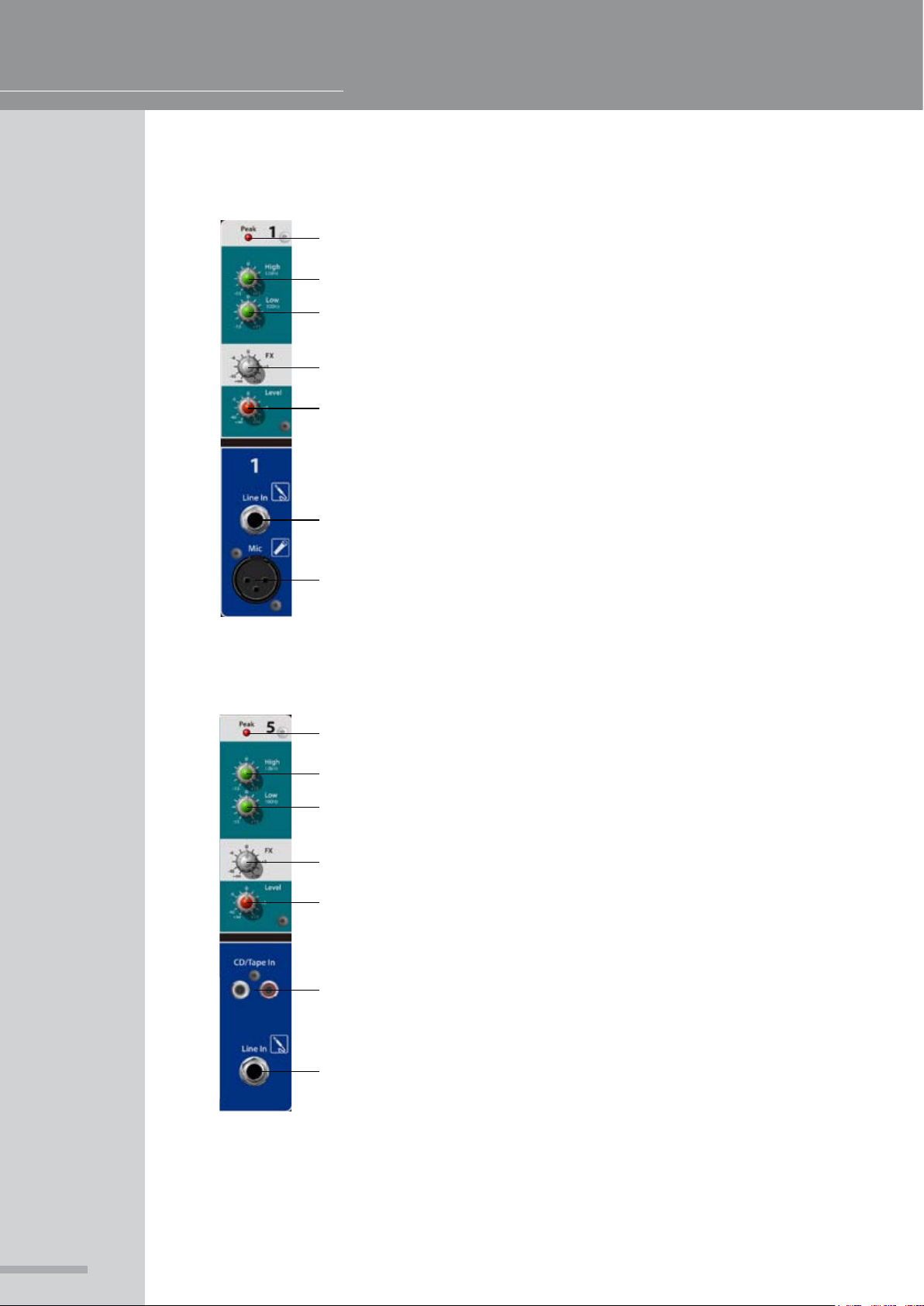
PMX 500 CHANNELS 1-4
1. Peak LED - Illuminates when the channel is clipping
2. High - High frequency shelving EQ, centered around 12kHz
3. Low - Low frequency shelving EQ, centered around 100Hz
4. FX Send - Sends signal to the built-in FX processor
5. Level - Controls the overall volume of the channel
6. Line in - Balanced / unbalanced ¼” TRS input for line level sources
7. Mic - Balanced XLR microphone input with switchable +48v phantom
powering (Global Phantom power switch on rear of PMX unit)
1
2
3
4
5
6
7
PMX 500 CHANNEL 5
1. Peak LED - Illuminates when the channel is clipping
2. High - High frequency shelving EQ, centered around 12kHz
3. Low - Low frequency shelving EQ, centered around 100Hz
4. FX Send - Sends signal to the built-in FX processor
5. Level - Controls the overall volume of the channel
6. CD/Tape In - Dual phono inputs for connection of consumer level
stereo sources, the input will be summed to mono
7. Line in - Balanced / unbalanced ¼” TRS input for line level sources
6
Page 9
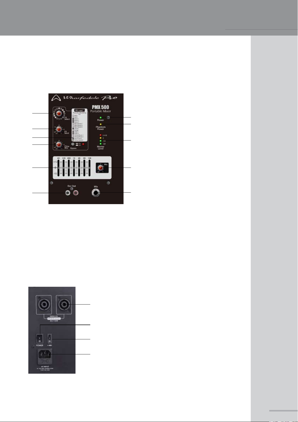
PMX 500 MASTER SECTION
. FX Select - Selects the effect type that
1
will be used
1
4
6
7
8
9
7. FX to Mix - Controls the output level of the internal FX processor to the master buss
8. 7-band EQ - Master section EQ to ne tune the overall sound
9. Rec Out - Line level output using phono connectors, provides connection to recording devices
0. Mix Level - Controls the main master volume
1
11. Mix output - Balanced / unbalanced ¼” TRS master output
2. Power LED - Indicates AC supply
3. Phantom Power LED - Indicates +48v
2
3
5
1
11
phantom powering is supplied to all of
the XLR inputs. Please check that all
connected microphones can withstand
+48v power input
4. FX Send - Allows for master adjustment
of the FX send buss
5. Master Level LED’s - 4 segment LED
0
metering for the master buss, if the
limit LED illuminates constantly lower
the master level to avoid damage to
your loudspeakers
6. Bypass - Used to switch the internal FX
processor on or off
PMX
Powered Mixer
PMX 500 REAR PANEL
1
2
3
4
1. Speakon™ outputs - Parallel outputs for connection to
your loudspeakers
PLEASE MAKE SURE THAT THE TOTAL
IMPEDANCE OF THE LOAD IS NOT LESS
THAN 4 OHMS.
2. Power Switch - Turns the unit on or off, ensure that AC
is supplied and that the levels have been turned down
to protect your speakers
3. Phantom Power switch - Activates the +48v phantom
powering for the 4 XLR inputs
4. IEC receptacle - Allows input of the supplied IEC lead
for AC supply
7
Page 10

OPERATING MANUAL AND USER GUIDE
1
2
3
4
5
6
7
8
9
PMX 700 CHANNELS 1-6
1. Peak LED - Illuminates when the channel is clipping
2. High - High frequency shelving EQ, centered around 12kHz
3. Mid - Mid frequency shelving EQ, centered around 2kHz
4. Low - Low frequency shelving EQ, centered around
5. Mon - Sends signal to a stage monitor
6. FX Send - Sends signal to the built-in FX processor
7. Level - Controls the overall volume of the channel
8. Line in - Balanced / unbalanced ¼” TRS input for line level sources
9. Mic - Balanced XLR microphone input with switchable +48v phantom
powering (Global Phantom power switch on rear of PMX unit)
100Hz
1
PMX 700 CHANNEL 7
1. Peak LED - Illuminates when the channel is clipping
2
2. High - High frequency shelving EQ, centered around 12kHz
3. Low - Low frequency shelving EQ, centered around 100Hz
3
4. Mon - Sends signal to a stage monitor
5. FX Send - Sends signal to the built-in FX processor
6. Level - Controls the overall volume of the channel
4
7. CD/Tape In - Dual phono inputs for connection of consumer level stereo
5
6
7
8
9
sources
8. Line in L - Balanced / unbalanced ¼” TRS input for left channel of line
level sources
9. Line in R - Balanced / unbalanced ¼” TRS input for right channel of line
level sources
8
Page 11

PMX
R
L
L
A B
B
B
A
A
R
-30
-10
0
Limit
Phantom
Power
Amp Mode
Power
Master
Level
Peak
Balance
Mon
FX
0
+10
-40
-6
+5
-∞
0
+10
-40
-6
+5
-∞
+15-15
0
+15-15
0
Low
100Hz
High
12kHz
Mix Left Mix Right Mon
Mon
Mix
0
-∞
0
-∞
PMX 710
Portable Mixer
+6
+6
+12
0
-12
60 120 480 1K 4K 8K 16K
+12
0
-12
60 120 480 1K 4K 8K 16K
7
RL
Rec Out
USB
Bypass
FX to
Mix
0
+10
-40
-6
+5
-∞
FX to
Mon
0
+10
-40
-6
+5
-∞
FX
Send
0
+10
-40
-6
+5
-∞
On
O
USB
Line
Hall 1
Hall 2
Room 1
Room 2
Room 3
Plate Reverb 1
Plate Reverb 2
Plate Reverb 3
Chorus
Flange
Delay 1
Delay 2
Chorus/Room 1
Chorus/Room 2
Vocal Cancel
Rotary Speaker
10
1
11
12
13
14
15
16
2
3
4
5
6
7
8
9
Acoustic Modeling
FX
Logic
TM
FX
Select
10
13
14
16
1
2
6
7
8
11
12
15
3
4
5
9
L R
0
+10
-40
-6
+5
-∞
R
L
L
A B
B
B
A
A
R
-30
-10
0
Limit
Phantom
Power
Amp Mode
Power
Master
Level
Pan
Level Level Level Level Level Level Level
Mon
FX
0
+10
-40
-6
+5
-∞
0
+10
-40
-6
+5
-∞
0
+10
-40
-6
+5
-∞
+15-15
0
+15-15
0
Low
100Hz
High
12kHz
+15-15
0
Mid
2kHz
Pan
Mon
FX
0
+10
-40
-6
+5
-∞
0
+10
-40
-6
+5
-∞
+15-15
0
+15-15
0
Low
100Hz
High
12kHz
+15-15
0
Mid
2kHz
Pan
Mon
FX
0
+10
-40
-6
+5
-∞
0
+10
-40
-6
+5
-∞
+15-15
0
+15-15
0
Low
100Hz
High
12kHz
+15-15
0
Mid
2kHz
Pan
Mon
FX
0
+10
-40
-6
+5
-∞
0
+10
-40
-6
+5
-∞
+15-15
0
+15-15
0
Low
100Hz
High
12kHz
+15-15
0
Mid
2kHz
Pan
Mon
FX
0
+10
-40
-6
+5
-∞
0
+10
-40
-6
+5
-∞
+15-15
0
+15-15
0
Low
100Hz
High
12kHz
+15-15
0
Mid
2kHz
Pan
Mon
FX
0
+10
-40
-6
+5
-∞
0
+10
-40
-6
+5
-∞
+15-15
0
+15-15
0
Low
100Hz
High
12kHz
+15-15
0
Mid
2kHz
Peak
Balance
Mon
FX
0
+10
-40
-6
+5
-∞
0
+10
-40
-6
+5
-∞
+15-15
0
+15-15
0
Low
100Hz
High
12kHz
Mix Left Mix Right Mon
Mon
Mix
0
-∞
0
-∞
PMX 710
Portable Mixer
+6
+6
+12
0
-12
60 120 480 1K 4K 8K 16K
+12
0
-12
60 120 480 1K 4K 8K 16K
7
RL
Rec Out
Line In
Mic
USB
Line In
Mic
Line In
Mic
Line In
Mic
Line In
Mic
Line In
Mic
Peak Peak Peak Peak Peak Peak
1 2 3 4 5 6
Bypass
FX to
Mix
0
+10
-40
-6
+5
-∞
FX to
Mon
0
+10
-40
-6
+5
-∞
FX
Send
0
+10
-40
-6
+5
-∞
On
O
USB
Line
Hall 1
Hall 2
Room 1
Room 2
Room 3
Plate Reverb 1
Plate Reverb 2
Plate Reverb 3
Chorus
Flange
Delay 1
Delay 2
Chorus/Room 1
Chorus/Room 2
Vocal Cancel
Rotary Speaker
10
1
11
12
13
14
15
16
2
3
4
5
6
7
8
9
Acoustic Modeling
FX
Logic
TM
FX
Select
10
13
14
16
1
2
6
7
8
11
12
15
3
4
5
9
L R
0
+10
-40
-6
+5
-∞
0
+10
-40
-6
+5
-∞
0
+10
-40
-6
+5
-∞
0
+10
-40
-6
+5
-∞
0
+10
-40
-6
+5
-∞
0
+10
-40
-6
+5
-∞
Powered Mixer
1
2
3
4
5
6
7
8
9
10
PMX 710 CHANNELS 1-6
1. Peak LED - Illuminates when the channel is clipping
2. High - High frequency shelving EQ, centered around 12kHz
3. Mid - Mid frequency shelving EQ, centered around 2kHz
4. Low - Low frequency shelving EQ, centered around
5. Mon - Sends signal to a stage monitor
6. FX Send - Sends signal to the built-in FX processor
7. Pan - Places the signal within the stereo eld
8. Level - Controls the overall volume of the channel
9. Line in - Balanced / unbalanced ¼” TRS input for line level sources
0. Mic - Balanced XLR microphone input with switchable +48v phantom
1
powering (Global Phantom power switch on rear of PMX unit)
100Hz
1
PMX 710 CHANNEL 7
1
2
3
4
5
6
7
8
9
10
. Peak LED - Illuminates when the channel is clipping
2. High - High frequency shelving EQ, centered around 12kHz
3. Low - Low frequency shelving EQ, centered around 100Hz
4. Mon - Sends signal to a stage monitor
5. FX Send - Sends signal to the built-in FX processor
6. Balance - Spatially places the signal within the stereo eld
7. Level - Controls the overall volume of the channel
8. CD/T
9. USB/Line Switch - Selects the input source for the channel
1
ape In - Dual phono inputs for connection of consumer level
stereo sources
0. USB Input - For connecting a computer, the PMX710 acts as an audio
interface
9
Page 12

OPERATING MANUAL AND USER GUIDE
PMX 700 / PMX 710 MASTER SECTION
1
4
5
7
8
0
1
11
2 13
1
1. FX Select - Selects the effect type that will
be used
2. Power LED - Indicates AC supply
2
3. Phantom Power LED - Indicates +48v
3
phantom powering is supplied to all of
6
9
14
the XLR inputs. Please check that all
connected microphones can withstand
+48v power input
4. FX Send - Allows for master adjustment of
the FX send buss
5. FX to Mon - Routes the FX processor
output to the Monitor send
6. Master Level LED’s - 4 segment LED
metering for the master buss, if the limit
LED illuminates constantly lower the
master level to avoid damage to your
loudspeakers
7. Bypass - Used to switch the internal FX
processor on or off
8. FX to Mix - Controls the output level of the internal FX processor to the master buss
9. Amp Mode - Congures the signal routing of the graphic EQ. With Mode ‘A’ each EQ controls
each respective output with the monitor sends routed unprocessed to the Mon output. In Mode
‘B’ The Mon is processed by the top EQ and the lower EQ controls will process both left and right
output channels.
10. 7-band EQ - 2 independent 7-band equalisers with exible A/B routing
1. Rec Out - Line level output using phono connectors, provides connection to recording devices
1
12. Mix Left - Balanced / unbalanced ¼” TRS master output for the left channel
13. Mix Right - Balanced / unbalanced ¼” TRS master output for the right channel
14. Mon - Balanced / unbalanced ¼” TRS Monitor send output
PMX 700 / PMX 710 REAR PANEL
1. Speakon™ outputs - For connection to your loudspeakers
1
2
3
4
2. Power Switch - Turns the unit on or off, ensure that AC
is supplied and that the levels have been turned down to
protect your speakers
3. Phantom Power switch - Activates the +48v phantom
powering for the 4 XLR inputs
4. IEC receptacle - Allows input of the supplied IEC lead for
AC supply
10
Page 13

PMX500 DIMENSIONAL DRAWINGS
AC INPUT
AC 220-240V~50Hz 2 50W
FUSE T1.6AL 250V
POWER
8 /150W
PARALLEL
Serial Numb er
PMX500
MODEL:
Portable Mixer
N 2317
48V
RISK OF ELECTRIC SHOCK
DO NOT OPEN
Peak
+12
0
-12
60 120 480 1K 4K 8K 16K
5
Peak
4
Peak
3
Peak
2
Peak
1
PMX 500
Portable Mixer
Rec Out
Mix
-30
-10
Limit
0
Phantom
Power
Power
Master
Level
Bypass
FX to
Mix
0
+10
-40
-6
+5
-∞
FX
Send
0
+6
-40
-6
+5
-∞
On
O
FX
Select
10
13
14
16
1
2
6
7
8
11
12
15
3
4
5
9
Mix
FXFXFXFXFX
0 0 0 0 0
Hall 1
Hall 2
Room 1
Room 2
Room 3
Plate Reverb 1
Plate Reverb 2
Plate Reverb 3
Chorus
Flange
Delay 1
Delay 2
Chorus/Room 1
Chorus/Room 2
Vocal Cancel
Rotary Speaker
10
1
11
12
13
14
15
16
2
3
4
5
6
7
8
9
Acoustic Modeling
FX
Logic
Line In
Line InLine InLine In
1
Line In
CD/Tape In
Mic Mic Mic Mic
2 3 4
Low
100Hz
Level
High
12kHz
Low
100Hz
Level
High
12kHz
Low
100Hz
Level
High
12kHz
Low
100Hz
Level
High
12kHz
Low
100Hz
Level
High
12kHz
0
0
0
0
0
0
0
0
0
0
0
0
0
0
0
392.05
260.92
242.95
PMX
Powered Mixer
11
Page 14

OPERATING MANUAL AND USER GUIDE
Line In L
Line In R
Line In
Mic
Line In
Mic
Line In
Mic
Line In
Mic
Line In
Mic
Line In
Mic
654321
L R
Low
100Hz
High
12kHz
Level
Low
100Hz
High
12kHz
Mid
2kHz
0
0
0
0
Level
Low
100Hz
High
12kHz
Mid
2kHz
0
0
0
0
Level
Low
100Hz
High
12kHz
Mid
2kHz
0
0
0
0
Level
Low
100Hz
High
12kHz
Mid
2kHz
0
0
0
0
Level
Low
100Hz
High
12kHz
Mid
2kHz
0
0
0
0
Level
Low
100Hz
High
12kHz
Mid
2kHz
0
0
0
0
0
0
Level
0
Peak
7
FX0FX0FX0FX0FX0FX0FX
0
0 0 0 0 0 0 0
R
L
L
A
B
B
B
A
A
R
Phantom
Power
Amp Mode
Power
Master
Level
Mix Left Mix Right Mon
Mon
Mix
PMX 700
Portable Mixer
+12
0
-12
60 120 480 1K 4K 8K 16K
+12
0
-12
60 120 480 1K 4K 8K 16K
Bypass
FX to
Mix
FX to
Mon
FX
Send
On
O
FX
Select
10
13
14
16
1
2
6
7
8
11
12
15
3
4
5
9
RL
Rec Out
0
0
0
Limit
0
10
30
Peak Peak Peak Peak Peak Peak
1 2 3 4 5 6
Mon Mon Mon Mon Mon Mon Mon
Hall 1
Hall 2
Room 1
Room 2
Room 3
Plate Reverb 1
Plate Reverb 2
Plate Reverb 3
Chorus
Flange
Delay 1
Delay 2
Chorus/Room 1
Chorus/Room 2
Vocal Cancel
Rotary Speaker
10
1
11
12
13
14
15
16
2
3
4
5
6
7
8
9
Acoustic Modeling
FX
Logic
4 /150Wx2
Portable Mixer
PMX700
MODEL:
Serial Number
AC 220V-240V~50Hz 500W
FUSE T3.15AL 250V
AC INPUT
N 2317
48V
POWER
RISK OF ELECTRIC SHOCK
DO NOT OPEN
392.05
260.92
242.95
PMX700 DIMENSIONAL DRAWINGS
12
Page 15

PMX710 DIMENSIONAL DRAWINGS
Pan
Level Level Level Level Level Level Level
0
+10
-40
-6
+5
-∞
+15-15
0
+15-15
0
Low
100Hz
High
12kHz
+15-15
0
Mid
2kHz
Pan
+15-15
0
+15-15
0
Low
100Hz
High
12kHz
+15-15
0
Mid
2kHz
Pan
+15-15
0
+15-15
0
Low
100Hz
High
12kHz
+15-15
0
Mid
2kHz
Pan
+15-15
0
+15-15
0
Low
100Hz
High
12kHz
+15-15
0
Mid
2kHz
Pan
+15-15
0
+15-15
0
Low
100Hz
High
12kHz
+15-15
0
Mid
2kHz
Pan
+15-15
0
+15-15
0
Low
100Hz
High
12kHz
+15-15
0
Mid
2kHz
Balance
+15-15
0
+15-15
0
Low
100Hz
High
12kHz
0
+10
-40
-6
+5
-∞
0
+10
-40
-6
+5
-∞
0
+10
-40
-6
+5
-∞
0
+10
-40
-6
+5
-∞
0
+10
-40
-6
+5
-∞
0
+10
-40
-6
+5
-∞
Line In
Mic
USB
Line In
Mic
Line In
Mic
Line In
Mic
Line In
Mic
Line In
Mic
USB
Line
L R
242.95
392.05
260.92
242.95
PMX
Powered Mixer
13
Page 16

OPERATING MANUAL AND USER GUIDE
PMX SYSTEM OVERVIEW
The Wharfedale Pro PMX System provides you with everything you need to get up and running for
a public performance.
• 1x PMX powered mixer
• 2x PT-X 2-way loudspeakers
• 1x DM 1.0 dynamic microphone
• 1x 4.5m microphone cable
• 2x speaker cables
A PMX System package comprises of a PMX powered mixer (PMX500 or PMX700), a pair of 2-way
loudspeakers (PTX-8 with the PMX 500 System and PTX-12 with the PMX700 System), a DM1.0
dynamic microphone and the necessary cables to connect the system.
Setting up a PMX System has been designed to be simple even for absolute beginners. Connect
the components as shown in the wiring diagram to create a basic vocal PA. Adding more equipment
is simple, always consult the user manual of any 3rd party equipment to ensure you will get the best
performance.
QUICK START GUIDE
In order to get up and running with your PMX System follow the steps below:
1. Zero the mixer. This involves setting all level and send controls to minimum and all EQ controls
to 0dB.
Make all connections for audio and power as per the wiring diagrams:
2.
1. Ensure that the power switch is on the off position before connecting the AC supply.
2. Connect the microphone using the supplied XLR cable
3. Connect each speaker to the main outputs using the supplied speaker cables
3. If your microphones require phantom power use the rear panel switch to activate +48V supply.
4. Turn the power switch on.
5. Raise the level control for each of your connected sources, ensure that the Peak LED does not
constantly illuminate.
Raise the Mix Level control until you achieve the desired Sound Pressure Level (SPL).
6.
NOTE
If the sound becomes distorted at higher volumes you may need to add extra equipment to achieve
the desired SPL, otherwise you may cause permanent damage to your system by overloading it.
14
Page 17

USB INTERFACE
The USB connector enables computers with USB connectivity to interface directly with the PMX 710
mixer for full duplex recording and playback. In recent years the introduction of USB connectivity
has ushered a new appreciation of the capabilities of computer audio, helping to fuse both digital
and analogue and open up endless possibilities for the recording musician.
The internal AD (Analogue to Digital) and DA (Digital to Analogue) converters are 16-bit/48KHz
enabling recording and playback above CD quality, ensuring that recordings that you make with a
10 have outstanding quality.
PMX 7
The PMX 710 is fully class compliant and requires no drivers when used with modern operating
systems. Mac OSX, Windows XP, Vista and 7 will require no additional driver software.
PMX
Powered Mixer
W
indows XP Installation
Simply choose the device in the following location: Start/Settings/Control Panel/Sounds and Audio
Devices/Audio
OSX Installation
Mac
Simply select as an input and output device using the "Audio MIDI Setup" page, you can nd this
easily using the spotlight function.
15
Page 18

OPERATING MANUAL AND USER GUIDE
16
Page 19

PMX
Pan
Level Level Level Level Level Level Level
0
+10
-40
-6
+5
-∞
+15-15
0
+15-15
0
Low
100Hz
High
12kHz
+15-15
0
Mid
2kHz
Pan
+15-15
0
+15-15
0
Low
100Hz
High
12kHz
+15-15
0
Mid
2kHz
Pan
+15-15
0
+15-15
0
Low
100Hz
High
12kHz
+15-15
0
Mid
2kHz
Pan
+15-15
0
+15-15
0
Low
100Hz
High
12kHz
+15-15
0
Mid
2kHz
Pan
+15-15
0
+15-15
0
Low
100Hz
High
12kHz
+15-15
0
Mid
2kHz
Pan
+15-15
0
+15-15
0
Low
100Hz
High
12kHz
+15-15
0
Mid
2kHz
Balance
+15-15
0
+15-15
0
Low
100Hz
High
12kHz
0
+10
-40
-6
+5
-∞
0
+10
-40
-6
+5
-∞
0
+10
-40
-6
+5
-∞
0
+10
-40
-6
+5
-∞
0
+10
-40
-6
+5
-∞
0
+10
-40
-6
+5
-∞
Line In
Mic
USB
Line In
Mic
Line In
Mic
Line In
Mic
Line In
Mic
Line In
Mic
USB
Line
L R
Powered Mixer
17
Page 20

OPERATING MANUAL AND USER GUIDE
PMX500 BLOCK DIAGRAM
18
Page 21

PMX700 BLOCK DIAGRAM
PMX
Powered Mixer
19
Page 22

OPERATING MANUAL AND USER GUIDE
PMX710 BLOCK DIAGRAM
20
Page 23

SPECIFICATIONS
PMX
Powered Mixer
Model
Power
Output
Maximum output level
Total harmonic distortion:
Hum & noise
Maximum voltage gain
Input channel equalisation
Graphic equaliser
Level meter
Limit indicator
Digital effects
Power
Productdimension(HxWxD)
Cartondimension(HxWxD)
Net weight
Gross weight
PMX 500
150W RMS into 4Ω
+22dBu (mix out (balanced))
≤0.4% @ 40Hz-20KHz 100w/4Ω (speaker out)
≤0.02% @ 20Hz-30KHz +14dBu (mix out)
-50dB residual output noise (speaker out)
-83dB residual output noise (mix out)
82dB input mic to speakers out
52dB input mic to mix out
42dB input mic to rec out
52dB input line to speakers out
±
15dB maximum
High 12kHz shelving
Low 100Hz shelving
7 bands (60Hz, 120Hz, 480Hz, 1KHz, 4KHz, 8KHz, 16kHz)
max: ±
12dB
4-segment LED (0dB output 0dBu on meter mix output)
Turns on approx +6dBu {Comp ≥140W (speakers out) / each CH}
6 Effects (Hall1; Hall2; Room1; Room2; Room3; Plate Reverb1;
1
Plate Reverb2; Plate Reverb3; Chorus; Flange; Delay1; Delay2;
Chorus/Room1; Chorus/Room2; Vocal Cancel; Rotary Speaker)
C100-120V~/220-240V, 50/60Hz
A
392 x 261 x 243mm
440 x 295 x 329mm
4.65 kg
5.85 kg
21
Page 24

OPERATING MANUAL AND USER GUIDE
SPECIFICATIONS
Model
Power Output
Maximum output level
Total harmonic distortion:
Hum& noise
Maximum voltage gain
Input channel equalisation
Graphic equaliser
Level meter
Limit indicator
Digital effects
Power
Productdimensions(HxWxD)
Cartondimensions(HxWxD)
Net weight
Gross weight
PMX 700
150W x 2 RMS into 4Ω
+22dBu
≤0.4% @40Hz-20kHz 100w/4Ω (speaker.out)
≤0.02% @20Hz-30kHz +14dBu (mix monitor out)
-50dB residual output noise (speaker out)
-83dB residual output noise (mix/monitor out)
82dB input mic to speakers out
52dB input mic to mix / monitor out
42dB input mic to rec out
52dB input line to speakers out
±15dB maximum
High 12kHz shelving
Mid 2kHz shelving
Low 100Hz shelving
7 bands (60Hz, 120Hz, 480Hz, 1KHz, 4KHz, 8KHz, 16kHz)
max: ±
4-segment LED x2 (0dB output 0dBu on meter mix L/R)
Turns on approx +6dBu {Comp ≥140W (speakers out) / each CH}
1
Plate Reverb2; Plate Reverb3; Chorus; Flange; Delay1; Delay2;
Chorus/Room1; Chorus/Room2; Vocal Cancel; Rotary Speaker)
AC10
392 x 261 x 243mm
440 x 295 x 329mm
5.45 kg
6.65 kg
(mix out (balanced))
12dB
6 Effects (Hall1; Hall2; Room1; Room2; Room3; Plate Reverb1;
0-120V~/220-240V, 50/60Hz
22
Page 25

SPECIFICATIONS
PMX
Powered Mixer
Model
Power
Output
Maximum output level
Total harmonic distortion:
Hum& noise
Maximum voltage gain
Input channel equalisation
Graphic equaliser
Level meter
Limit indicator
Digital effects
Power
Productdimension(HxWxD)
Cartondimension(HxWxD)
Net weight
Gross weight
PMX 710
250W x 2 RMS into 4Ω
+28dBu (mix out (balanced))
≤0.4%@40Hz-20kHz 100w/4Ω(speakers out)
≤0.02%@20Hz-30kHz +14dBu(mix/monitor out)
-50dB residual output noise(speakers out)
-83 dB residual output noise(mix/monitor out)
88dB input mic to speakers out
58dB input mic to mix/monitor out
48dB input mic to rec out
54dB input line to speakers out
58dB input tape&usb to speakers out
+/-
15 dB maximum
High 12kHz shelving
Mid 2kHz shelving
Low 100Hz shelving
7bands(60Hz, 120Hz, 480Hz ,1kHz, 4kHz, 8kHz ,16kHz)
Max: +/-
4-Segment LED x2 (0dB output 0dBu on meter mix L/R)
Turns on approx +6 dBu {Comp ≥240W (speakers out) / each CH}
16 Effects(Hall1, Hall2, Room1, Room2, Room3,Plate Reverb1,
Plate Reverb2, Plate Reverb3,Chorus, Flange, Delay1, Delay2,
Chorus/Room1, Chorus/Room2,Vocal Cancel, Rotary Speaker)
AC100-120V~/220-240V, 50/60Hz
392 x 261 x 243mm
440 x 295 x 329mm
5.7 kg
6.9 kg
12 dB
23
Page 26

OPERATING MANUAL AND USER GUIDE
MODEL
Frequencyresponse(+/-10dB)
Frequencyresponse(+/-3dB)
Power handling
Continuous
Programme
Peak
Nominal
Sensitivity(dBSPL@1W/1M)
MaxSPL(Calculated)
Nominalcoverage(HxV)
Crossover frequency
Woofer
LFPower(RMS)
Sensitivity(freeeld1W@1M)
LF Voice coil
Cone material
LF Voice coil material
LF Voice coil former material
Basket material
Basket type
Magnet structure mass
Magnet structure material
LF Driver part number
HFPower(RMS)
Sensitivity(freeeld1W@1M)
HF Voice coil
Waveguide Type
Waveguide Exit
Diaphragm material
HF Voice coil former material
Magnet structure mass
Magnet structure material
Protection
HF driver part number
Enclosure Material and Thickness
Enclosure Finish
Enclosure Volume
Grille Material & Finish
Pole mount
Handles
Input
Net Weight
kg
lbs
Dimensions
H
W
D
Impedance
Connector Type
(Unpacked)
PT-X8
65-20kHZ
70-20kHZ
75W
1
50W
300W
8Ω
95dB
1
19dB
90°x60°
3.0kHz
205mm/8"
75w
95dB
1
.5"
Paper
Copper
Fibre glass
Steel
Pressed
0.792kg/
Ferrite
ZD-75600-0
25W
1
1"
Elliptical
1.2"
Phenolic
Kapton
0.365kg/0.803lbs
Ferrite
PTC
ZD-53200-0
12mm particle
Black carpet
14.3L
1.2mm steel
35mm
2 on sides
2x
8.1
17.8
429mm / 16.9"
280.7/146.7mm / 11.1/5.8"
250mm / 9.8"
1.73lbs
1R
07dB
1R
1/4" phone Jack
-X12
PT
55-20KHZ
60-20KHZ
250W
500W
000W
1
4Ω
97dB
126dB
90°x60°
3.0kHz
305mm/12"
250w
97dB
2"
Paper
Copper
Fibre glass
Steel
Pressed
1
.24kg/2.7lbs
Ferrite
1-07010065A
L0
25W
07dB
1
1"
Elliptical
1.2"
Phenolic
Kapton
0.365kg/0.803lbs
Ferrite
PTC
ZD-53200-0
12mm particle
Black carpet
31.8L
1.2mm steel
35mm
2 on sides
2x
1/4" phone Jack
12.85
25.7
525mm / 20.7"
370.7/207.3mm / 14.6"/ 8.2"
305mm / 12"
1R
24
Page 27

PMX
Powered Mixer
PMX System Microphone
Frequency response
Type
Magnet
Polar pattern
Output connector
material
DM1.0
50Hz-18kHz
Dynamic
Neodymium
Cardioid
3-pin gold plated balanced male XLR
WHARFEDALE PRO LIMITED WARRANTY
Wharfedale Pro PMX Series products are warranted of manufacturing or material defects for a
period of one year from the original date of purchase. In the event of malfunction, contact your
authorized Wharfedale Pro dealer or distributor for information.
*Be aware that warranty details may differ from country to country. Contact your dealer or
distributor for information. These terms do not infringe your statutory rights.
25
Page 28

Wharfedale Professional
IAG House, 13/14 Glebe Road, Huntingdon, Cambridgeshire, PE29 7DL, UK
www.wharfedalepro.com
Wharfedale Professional reserves the right to alter or improve specications without notice.
All rights reserved © 2011 Wharfedale Pro. Wharfedale Pro is a member of the IAG Group.
 Loading...