

Page 1
User Guide
6650-2260
LRW-102
SERIES
©
Westermo Teleindustri AB
PWR
PKT
CH 1
CH 2
TD
FL L
RD
FL R
1
L2 L1
2
STATUS
LRW-100 Series
1
LON
N2 N1
2
Fibre Optic industrial
converter/repeater
for LonWorks
®
TP/FT-10
point-to-point,
line and redundant ring
www.westermo.com
Page 2

Legal information
The contents of this document are provided “as is”. Except as required by applicable
law, no warranties of any kind, either express or implied, including, but not limited to,
the implied warranties of merchantability and fitness for a particular purpose, are made
in relation to the accuracy and reliability or contents of this document. Westermo
reserves the right to revise this document or withdraw it at any time without prior
notice.
Under no circumstances shall Westermo be responsible for any loss of data or income
or any special, incidental, and consequential or indirect damages howsoever caused.
More information about Westermo can be found at the following Internet address:
http://www.westermo.com
2
6650-2260
Page 3

Safety
!
!
!
Before installation:
Read this manual completely and gather all information on the unit. Make sure that
you understand it fully. Check that your application does not exceed the safe operating specifications for this unit.
This unit should only be installed by qualified personnel.
This unit should be built-in to an apparatus cabinet, or similar, where access is
restricted to service personnel only.
The power supply wiring must be sufficiently fused, and if necessary it must be
possible to disconnect manually from the power supply. Ensure compliance to
national installation regulations.
This unit uses convection cooling. To avoid obstructing the airflow around the unit,
follow the spacing recommendations (see Cooling section).
Before mounting, using or removing this unit:
Prevent access to hazardous voltage by disconnecting the unit from power supply.
Warning! Do not open connected unit. Hazardous voltage may occur within this
unit when connected to power supply.
Class 1 Laser Product
Do not look directly into fibre optical fibre port or any connected fibre although
this unit is designed to meet the Class 1 Laser regulations.
Care recommendations
Follow the care recommendations below to maintain full operation of unit and to fulfil
the warranty obligations.
This unit must not be operating with removed covers or lids.
Do not attempt to disassemble the unit. There are no user serviceable parts inside.
Do not drop, knock or shake the unit, rough handling above the specification may cause
damage to internal circuit boards.
Do not use harsh chemicals, cleaning solvents or strong detergents to clean the unit.
Do not paint the unit. Paint can clog the unit and prevent proper operation.
Do not expose the unit to any kind of liquids (rain, beverages, etc). The unit is not water-
proof. Keep the unit within the specified humidity levels.
Do not use or store the unit in dusty, dirty areas, connectors as well as other mechanical
part may be damaged.
If the unit is not working properly, contact the place of purchase, nearest Westermo dis-
tributor office or Westermo Tech support.
Fibre connectors are supplied with plugs to avoid contamination inside the optical port.
As long as no optical fibre is mounted on the connector, e.g. for storage, service or
transportation, should the plug be applied.
6650-2260
3
Page 4

Note. Fibre Optic Handling
Fibre optic equipment needs special treatment. It is very sensitive to dust and dirt. If
the fibre will be disconnected from the modem the protective hood on the transmitter/
receiver must be connected. The protective hood must be kept on during transportation.
The fibre optic cable must also be handle the same way.
If this recommendation not will be followed it can jeopardise the warranty.
Cleaning of the optical connectors
In the event of contamination, the optical connectors should be cleaned by the use of
forced nitrogen and some kind of cleaning stick.
Recommended cleaning fluids:
• Methyl-, ethyl-, isopropyl- or isobutyl-alcohol
• Hexane
• Naphtha
Maintenance
No maintenance is required, as long as the unit is used as intended within the specified
conditions.
Agency approvals and standards compliance
Type Approval / Compliance
EMC EN 61000-6-1, Immunity residential environments
EN 61000-6-2, Immunity industrial environments
EN 61000-6-3, Emission residential environments
EN 61000-6-4, Emission industrial environments
EN 55022, Emission IT equipment, class A
EN 55024, Immunity IT equipment
FCC part 15 Class A
Safety EN 60950-1, IT equipment
FCC Part 15.105
Notice:
This equipment has been tested and found to comply with the limits for a Class A
digital device, pursuant to Part 15 of the FCC Rules. These limits are designed to provide
reasonable protection against harmful interference when the equipment is operated in a
commercial environment.
This equipment generates, uses, and can radiate radio frequency energy and, if not
installed and used in accordance with the instruction manual, may cause harmful interference to radio communications. Operation of this equipment in a residential area is likely
to cause harmful interference in which case the user will be required to correct the
interference at his own expense.
EN 55022 Notice:
4
This is a class A product. In a domestic environment this product may cause radio interference in which case the user may be required to take adequate measures.
6650-2260
Page 5
Declaration of Conformity
Westermo Teleindustri AB
Declaration of conformity
The manufacturer
Herewith declares that the product(s)
Type of product Model Art no
Industrial Converter/Router
is in conformity with the following EC directive(s).
No Short name
2004/108/EC Electromagnetic Compatibility (EMC)
References of standards applied for this EC declaration of conformity.
No Title Issue
EN 55022 Information technology equipment - Emission 2006 +A1:2007
EN 55024 Information technology equipment - Immunity 1998 +A1:2001
EN 61000-6-1 Electromagnetic compatibility – Immunity for
EN 61000-6-2 Electromagnetic compatibility – Immunity for
EN 61000-6-3 Electromagnetic compatibility – Emission for
EN 61000-6-4 Electromagnetic compatibility – Emission for
Westermo Teleindustri AB
SE-640 40 Stora Sundby, Sweden
residential environments
industrial environments
residential environments
industrial environments
LRW-100 Series
3650-1xxx
+A2:2003
2007
2005
2007
2007
The last two digits of the year in which the CE marking was affixed: 09
Pierre Öberg
Technical Manager
26th October 2009
Postadress/Postal address
S-640 40 Stora Sundby 016-428000 016-428001 52 72 79-4 5671-5550 556361-2604 Eskilstuna
Sweden Int+46 16428000 Int+46 16428001
Org.nr/
Tel.
Telefax
Postgiro
Bankgiro
Corp. identity number Registered office
6650-2260
5
Page 6

Type tests and environmental conditions
Electromagnetic Compatibility
Phenomena Test Description Level
ESD EN 61000-4-2 Enclosure contact ± 4 kV
Enclosure air ± 8 kV
RF field AM modulated IEC 61000-4-3 Enclosure 10 V/m 80% AM (1 kHz), 80 – 1 000 MHz
Fast transient EN 61000-4-4 Signal ports ± 1 kV
Power ports ± 2 kV
Surge Signal ports balanced ± 1 kV line to earth, ± 1 kV line to line
Power ports ± 0.5 kV line to earth, ± 0.5 kV line to line
RF conducted EN 61000-4-6 Signal ports 10 V 80% AM (1 kHz), 0.15 – 80 MHz
Power ports 10 V 80% AM (1 kHz), 0.15 – 80 MHz
Power frequency
magnetic field
Pulse Magnetic field EN 61000-4-9 Enclosure 300 A/m, 6.4 / 16 μs pulse
Voltage dips and
interruption
Mains freq. 50 Hz EN 61000-4-16 Signal ports 100 V 50 Hz line to earth
Mains freq. 50 Hz SS 436 15 03 Signal ports 250 V 50 Hz line to line
Voltage dips
and interruption
Radiated emission EN 55022 Enclosure Class B
Conducted emission EN 55022 AC power ports Class B
Dielectric strength EN 60950 Signal port to all other
Environmental
Temperature Operating –40 to +70ºC LRW-102PP
Humidity Operating 5 to 95% relative humidity
Altitude Operating 2 000 m / 70 kPa
Service life Operating 10 years
Vibration IEC 60068-2-6 Operating 7.5 mm, 5 – 8 Hz
Shock IEC 60068-2-27 Operating 15 g, 11 ms
Packaging
Enclosure UL 94 PC / ABS Flammability class V-1
Dimension W x H x D 35 x 121 x 119 mm
Weight 0.26 kg
Degree of protection IEC 529 Enclosure IP 21
Cooling Convection
Mounting Horizontal on 35 mm DIN-rail
EN 61000-4-8 Enclosure 100 A/m, 50 Hz, 16.7 Hz & 0 Hz
EN 61000-4-11 AC power ports 10 & 5 000 ms, interruption
10 & 500 ms, 30% reduction
100 & 1 000 ms, 60% reduction
EN 61000-4-29 DC power ports 10 & 100 ms, interruption
10 ms, 30% reduction
10 ms, 60% reduction
+20% above & –20% below rated voltage
FCC part 15 Class A
FCC part 15 AC power ports Class B
EN 55022 DC power ports Class A
1.5 kVrms 50 Hz 1min
isolated ports
Power port to other
isolated ports
Storage & Transport –40 to +70°C
Storage & Transport 5 to 95% relative humidity
2 kVrms 50 Hz 1min
–40 to +60ºC LRW-102
2 g, 8 – 500 Hz
6
6650-2260
Page 7

Description
The LRW-102 (LRW-102PP) offers an easy way to extend the distance between
®
LONWORKS
The LRW-102PP is a fibre optic modem used for point-to-point applications and the
LRW-102 is used for multidrop and redundant ring applications. It acts as a repeater
between the two fibre optic links, and as a converter between fibre optical links and the
LON TP/FT port. The maximum distance of the fibre links depends on selected transceiver and fibre types.
The LRW-102 (LRW-102PP) is designed for harsh outdoor usage, in industrial, road or
railway installations. The complete transparent conversion to and from the fibre optic
media facilitates the installation procedure by eliminating the need for any additional
network addressing or software configuration.
Convert LON TP/FT-10 interface – optical fibre
Multidrop, point-to-point alternatively redundant ring communication …
via fibre optical network
Small Form Factor Pluggable (SFP) transceivers …
LC fibre connectors, single or multimode …
78 kbit/s TP/FT network segments using a fibre optic link.
LC-2 Multimode LC connectors, 5 km (3.1 miles) …
LC-15 Singlemode LC connectors, 15 km (9.3 miles) …
Bi-di, Multimode LC connectors, 5 km (3.1 miles) …
Bi-di, Singlemode LC connectors, 20 km (12.4 miles) …
Redundant power supply, 2 kVAC galvanic isolated to other ports …
Designed for harsh environments …
Re-timing …
Status port …
LONWORKS® interface
2-positions detachable screw terminal …
Data rate 78 kbit/s …
6650-2260
7
Page 8
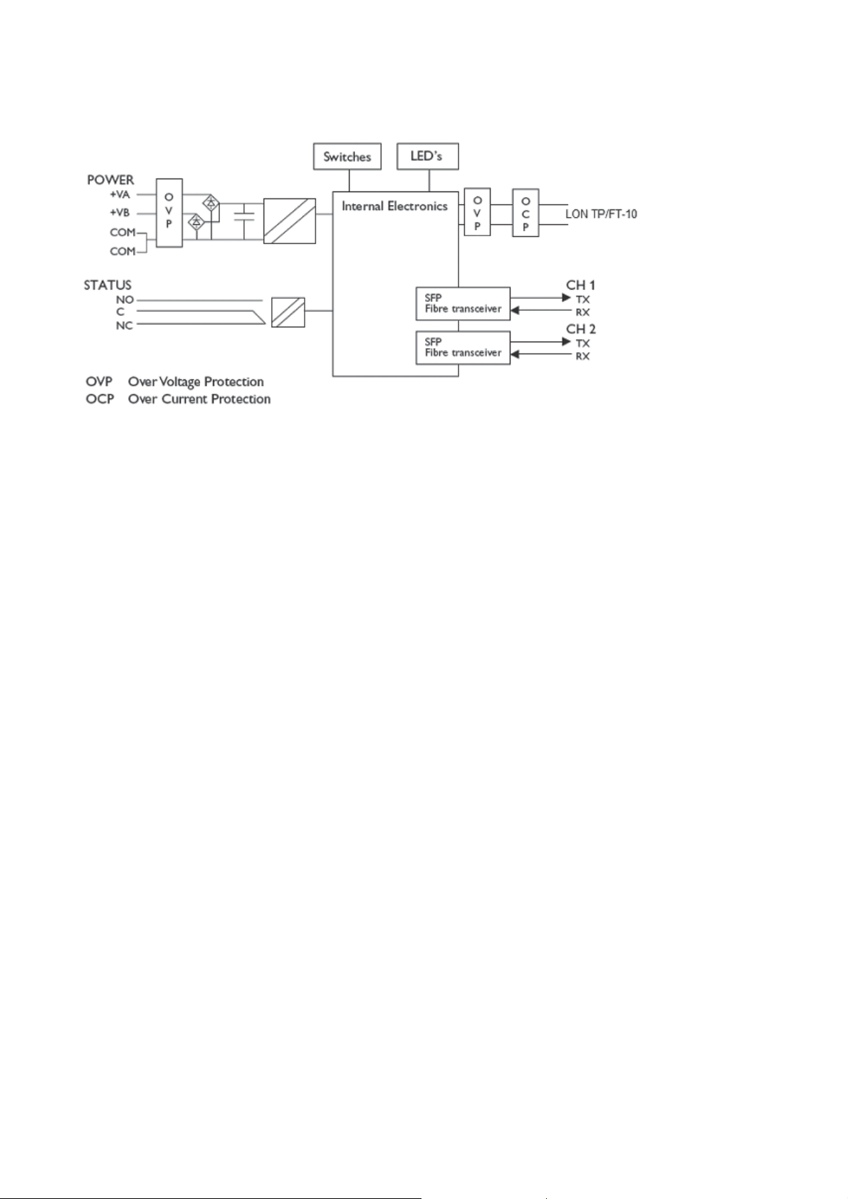
Functional description
Converter TP/FT interface – optical fibre
The LRW-102 (LRW-102PP) is a fibre optic converter that converts between
ONWORKS
L
®
TP/FT, and fibre optical link.
Repeater – optical fibre links
The LRW-102 is a fibre optic repeater that repeats received data from one fibre link out
to the other link. This is useful e.g. for long distance communication, where electromagnetic interference may occur or when isolation of the electrical network is needed.
Single or multimode LC fibre connectors
The LRW-102 (LRW-102PP) uses Small Form Factor Pluggable (SFP) transceivers that
are in compliance with Multi-Sourcing Agreement (MSA). A wide range of different fibre
transceivers and connectors can be used.
8
6650-2260
Page 9

Point-to-point communication via fibre optic network
With only two network segments, the most cost effective solution is to use two pointto-point LRW-102PP units to create a single fibre optic connection.
The point-to-point connection provides a totally transparent fibre link which means that
all data received on one units TP/FT port will be forwarded unchanged to the other port,
as illustrated in the figure.
POWER CH 1
COM +VA +VB COM
Fibre optical connection
at point-to-point communication
POWER CH 1
COM +VA +VB COM
TX/
RX
Fibre optical connection
at point-to-point communication (Bi-di transceiver)
Note: Bi-di fibre can be used.
The bi-di transceivers must always be used in pair, see example:
POWER CH 1
COM +VA +VB COMTX RX TX RX
POWER CH 1
COM +VA +VB COM
TX/
RX
TX
RX
Bi-di transceiver, TX 1550 nm, RX 1310 nm
1550 nm
RX
TX
1310 nm
Bi-di transceiver, TX 1310 nm, RX 1550 nm
6650-2260
9
Page 10

Redundant ring communications via fibre optic network
Under normal operation the LONWORKS® data is sent over ring A. Should a fault be
®
detected on the fibre ring then the LONWORKS
The LRW-102 units could be linked together to form a fibre optic ring. With ring topol-
ogy, a built-in redundancy scheme offers communication fault tolerance.
CH 2 CH 1 CH 2 CH 1 CH 2 CH 1 CH 2 CH 1
TX RX TX RX TX RX TX RX TX RX TX RX TX RX TX RX
data will be carried on rings A and B.
LON
Network
Ring A
Ring B
LON
Network
LON
Network
LON
Network
Normal operation
When LRW-102 unit receives data from the LON network, the LRW-102 (the initiator)
will transmit the data onto the fibre ring. During normal operation the data will be transmitted onto ring A. Data received by the other LRW-102 units in the ring is transmitted
over to the corresponding LON network as well as forwarded in the fibre ring. When a
LRW-102 initiator receives its own data packet, the packet it stopped. A LRW-102 initiator will not forward another packet while waiting for its own packet to return.
10
6650-2260
Page 11

Behaviour under faulty condition
Elapsed time from any kind of failure at the fibre optic network until data exchange after
a corrective action depends on total length of fibre ring. This is typically 40–500 ms.
During that time, the transferred data frames should be seen as corrupted or missed.
Failure Indications
Fibre interruption ring A, TX On: FL R
Fibre interruption ring A, RX On: FL L
Fibre interruption ring A, RX & TX On FL L
Fibre interruption ring B, TX On: FL R
Fibre interruption ring B, RX On: FL L
Fibre interruption ring B, RX & TX On: FL L
Fibre interruption ring A and B
(e.g. CH1 or CH2 both TX & RX)
* Regarding functionality see chapter “multi drop application”
On: FL L &/
or FL R
Recovery from faulty status
LRW-102 will automatically recover to the previous operating status when a failure
disappears. This involves recovery from bus/multi drop network to Redundant ring A/B
when ring is up and running and recovery from Ring B to Redundant ring A when the
ring is up and running. The time to recover from the failure status depends on total
length of fibre ring. This is typically 40–500 ms. During that time the transferred data
frames should be seen as corrupted or missed.
6650-2260
11
Page 12

Bus or multidrop communications via fibre optic network
CH 2 CH 1 CH 2 CH 1 CH 2 CH 1 CH 2 CH 1
TX RX TX RX TX RX TX RX TX RX TX RX TX RX TX RX
LON
Network
LON
Network
LON
Network
LON
Network
The data is transferred via the fibre optic network to the serial ports of all units. If
LRW-102 is connected to two optical fibre links (mid unit) converted data will be transmitted in both directions, via both CH 1 and CH 2. With only one optical fibre link (end
unit) converted data will be transmitted in one direction, via CH 1 only. Data received
from one LRW-102 optical fibre port will be repeated through the other optical fibre
port and it will also convert the frame to serial data.
Optical fibre link functionality and status indication
At power on, all LED's will be active during an initiation sequence followed by an automatic initiation of the optical fibre links. The alarm will be set until the fibre optical links
are in operation and ready to transfer serial data.
Data can be transferred over a fibre optical link as long as the link is in operation, indicated by active CH1 respective CH2.
When any of the fibre optical links is out of operation and this is a faulty state, will it be indicated by a local alarm and set the alarm output. It will also send a remote alarm via the other
link, if possible. When the link returns to operations mode, the alarm will reset automatically.
Redundant power supply, galvanic isolated (2 kVAC) to other ports.
LRW-102 (LRW-102PP) should be supplied with safety extra low voltage (SELV). It is
designed to operate permanently over a wide input range and provided with two independent inputs, allowing redundancy should either supply fail.
Single or multimode LC fibre connectors
The LRW-102 (LRW-102PP) uses Small Form Factor Pluggable (SFP) transceivers that
are in compliance with Multi-Sourcing Agreement (MSA). A wide range of different fibre
transceivers and connectors can be used.
Note: Bi-Di fibre can be used.
Status interface
This interface enables supervision of fibre optic link state.<8 ohm means that status is OK.
The fault state will be set if:
Local or remote fibre link errors exist. …… The unit is out of service, e.g. no power supply.
12
6650-2260
Page 13

LON Channel delay
The LON TP/FT-10 (EIA-709.3) specification states a maximum delay of 36 μs and a maximum of one repeater between any two nodes. Using the LRW-102 this delay restriction
will normally be met if the total fibre cable length is restricted to 5.6 km 3.5 mile).
®
When two or more LRW-102 is used on a LON
physical repeater link. As with a normal FTT-FTT physical repeater, the LRW-102 link
also forms a new channel segment and regenerates the signal allowing more nodes to be
installed.
It is important that the user is aware of the limitations involved with a physical extension
of an FTT channel. The LRW-102 units can transparently forward LonTalk
also assure that the required signal level is kept throughout the channel extension.
However, cable length between the units will impose an extra propagation delay on the
channel that could conflict with the media access timing used by the LonTalk
Increasing the propagation delay results in a higher probability for packet collisions, especially for a busy channel.
A normal FTT channel is dimensioned for one physical repeater allowing a maximum distance of 5400 metres (2 x 2700 metres) or 3.4 mi (2 x 1.7 mi).
For a busy channel it is recommended to use the LRW-112 router instead for the
LRW-102 converter. With the LRW-112 router, the delay is not a problem since it uses a
dedicated fibre optic channel where the propagation delay is accounted for.
®
It is recommended to use a LON
protocol analyser to verify network performance during high peak channel access. If an increased number of packets collisions and retries are
found we recommend using the LRW-112 router instead.
free topology network they form a
®
packet and
®
protocol.
According to the EIA-709.3, the delay through a repeater link must not exceed 36 μs.
To honour that requirement the following relation should be used:
Fibre distance (m) / 200 + Number of units < 36
Recommended max number of units = 10
For example, the above relation would allow two LRW-102 units to use a maximum fibre
optic cable length of 6.2 km (3.8 mi).
The EIA-709.3 recommendation is strict and shall handle 100% load on a network,
decreasing the load gives possibility to increase the allowed delay in the network.
Westermo has made tests with 60% load on the TP/FT-10 network and up to 60% load
it is possible to increase the allowed delay to 127 μs.
The following relation can be used on networks with up to 60% load
Fibre distance (m) / 200 + Number of units < 127
Recommended max number of units = 10
For example, the above equation would allow 10 LRW-102 units to use a maximum fibre
optic cable length of 23.4 km (15 miles).
The above discussion considers the limitation in maximum distance due to protocol
parameters involving media access and network idle detection. As with all fibre optic
products, the maximum distance is also dependent on the over all power budget
(see page 15).
6650-2260
13
Page 14

Interface specifications
Power
Rated voltage 12 to 48 VDC
24 VAC
Operating voltage 10 to 60 VDC
20 to 30 VAC
Rated current 400 mA @ 12 VDC
200 mA @ 24 VDC
100 mA @ 48 VDC
Rated frequency DC
AC: 48 to 62 Hz
Inrush current I
Startup current* 1.0 A
Polarity Reverse polarity protected
Redundant power input Yes
Isolation to TP/FT-10 port and status port
Galvanic connection to –
Connection 4-position detachable screw terminal
Connector size 0.2 – 2.5 mm
Shielded cable Not required
* External supply current capability for proper start up.
2
t 0.2 A2s
peak
2
(AWG 24 – 12)
Status
Port type Solid state relay
Operating voltage Up to 60 VDC
Load current Up to 100 mA
Contact resistance 8 Ω
Isolation to TP/FT-10 port and power port
Connection 2-position detachable screw terminal
Connector size 0.2 – 2.5 mm
2
(AWG 24 – 12)
TP/FT-10
Electrical specification L
ONWORKS
®
TP/FT-10 using FTT-10A transceiver
Data rate 78.5 kbit/s
Data format Synchronous
Protocol LonTalk
®
Transmission range Up to 2700 m
Termination Single or double external termination according to TP/FT-10
specification
Isolation to Power port and status port
Connection 2-positon detachable screw terminal
Connector size 0.2 – 2.5 mm
2
(AWG 24 – 12)
Shielded cable Not required
Conductive housing No
14
6650-2260
Page 15

Optical Power Budget
The maximum supported link lengths as specified in the table above should only been seen as indicative. The allowed link length is calculated from the Optical Power Budget (OPB), (the available optical
power for a fibre-optic link), and the attenuation of the fibre, comprising losses due to in-line connectors, splices, optical switches and a margin for link aging (typical 1.5 dB for 1300 nm).
The worst-case Optical Power Budget (OPB) in dB for a fibre-optic link is determined by the difference between the minimum transmitter output optical power and the lowest receiver sensitivity.
FX (Fibre) SM-LC15 MM-LC2
Fibre connector LC duplex LC duplex
Fibre type Singlemode
9/125 mm
62.5/125 and 50/125 mm
Multimode,
Wavelength nm 1310 1310
Transmitter
–15/–8 dBm** –20/–14 dBm*
Output optical power min/max
Receiver
–31 dBm –31 dBm
Input sensitivity, max
Receiver
–8 dBm –8 dBm
Input optical power, max
Optical power budget,
16 dB 11 dB
worst-case
Transceiver type Small Form Factor Pluggable (SFP)
Multi-Sourcing Agreement (MSA) compliant
Laser class Class 1, IEC 825-1 Accessible Emission Limit (AEL)
FX (Fibre)
Bi-di
LC-20
Bi-di
MM LC-2
Fibre connector LC Simplex LC Simplex
Fibre type Singlemode
9/125 μm
Wavelength nm, connector 1
Wavelength nm, connector 2
Transmitter
Tx1310, rx 1550 TX 1550,
rx 1310
-10/0 dBm ** –10/–8 dBm *
62.5/125 and 50/125 μm
Tx 1310, rx 1550 Tx 1550,
Multimode
rx 1310
Output optical power min/max
Receiver
–28 dBm –28 dBm
Input sensitivity, max
Receiver
0 dBm –0 dBm
Input optical power, max
Optical power budget,
18 dB 18 dB
worst-case
Transceiver type Small Form Factor Pluggable (SFP)
Multi-Sourcing Agreement (MSA) compliant
Laser class Class 1, IEC 825-1 Accessible Emission Limit (AEL)
* Output power is power coupled into a 62.5/125 μm multimode fibre
** Output power is power coupled into a 9/125 μm singlemode fibre
*** The optical power should be reduced by at least 5 dB (SM-LC80 and Bi-di LC-60)
or 3dB (SM-LC-40 and Bi-di LC-40) between the optical output and input.
6650-2260
15
Page 16

PWR
CH 1
TD
FL L
RD
FL R
PKT
CH 2
CH 1
COM +VA +VB COM
TX RX
LON
STATUS
N2 N1
L2 L1
LRW-100 Series
CH 2
TX RX
1
2
2
1
PWR
CH 1
TD
FL L
RD
FL R
PKT
CH 2
CH 1
COM +VA +VB COM
TX RX
LON
STATUS
N2 N1
L2 L1
LRW-100 Series
CH 2
TX RX
1
2
2
1
Location of Interface ports, LED’s and DIP-switches
LRW-102/ LRW-102PP
LED Indicators(for details see page 17)
Status
Position Direction* Description Product
marking
FX (Fibre)
Ch 1 and Ch 2.
(Ch 2 on
LRW-102 only)
For fibre details
see page 15.
1 In/Out Contact with posi-
1
tion 2 when fibre
optical links are in
operation
2 In/Out Common 2
TP/FT-10
Position Direction* Description Product
marking
1 In/Out TP/FT-10
connection
2 In/Out TP/FT-10
connection
N1
N2
16
Power
Position Direction* Description Product
marking
1 In Common voltage COM
2 In Voltage A +VA
3 In Voltage B +VB
4 In Common voltage COM
* Direction relative this unit
6650-2260
Page 17

LED indicators
LED Status Description
PWR
Power
ON In service (power)
Flashing Fault condition
OFF Out of service
PKT Not
–
used
Not
–
used
CH 2 ON Fibre link at port CH 2 in operation.
Data can be transmitted.
(Not used in pp version)
OFF Fibre link at port CH 2 out of operation.
(Not used in pp version)
CH 1 ON Fibre link at port CH 1 in operation.
Data can be transmitted.
OFF Fibre link at port CH 1 out of operation.
TD Flashing Receive accepted data on the serial port.
Data will be transmitted to the fibre link.
PWR
PKT
TD
RD
CH 1
CH 2
FL L
FL R
OFF –
RD Flashing Receive data on the fibre link that is
transmitted to the serial port.
OFF –
FL R (Red) ON Remote fibre link failure. A fibre link is
out of operation at any other unit of the
optical network.
OFF All fibre links are in operation at all
other units in the fibre optical network.
FL L (Red) ON Local fibre link failure. This unit has
identified a fibre link failure.
OFF Fibre link of this unit is in operation.
6650-2260
17
Page 18

Configuration
!
All needed configurations and parameter settings are done by the DIP-switches, located
under the top lid of the LRW-102 (LRW-102PP).
S2S1
DIP-switch settings
Before DIP-switch settings:
Prevent damage to internal electronics from electrostatic discharges (ESD) by
discharging your body to a grounding point (e.g. use of wrist strap)
Note: Disconnect power before DIP-switch settings.
S1 DIP-switch
ON
Not used
1 2 3 4 5 6 7 8
S2 DIP-switch
ON
1 2 3 4 5 6 7 8
ON
1 2 3 4 5 6 7 8
ON
1 2 3 4 5 6 7 8
Set status output at local
or remote error
Set status interface
at local fibre link error
(Not used in pp version)
Multidrop end unit
(use chanal 1 for end unit,
not used in pp version)
Factory settings
ON
1 2 3 4 5 6 7 8
S1
ON
1 2 3 4 5 6 7 8
ON
1 2 3 4 5 6 7 8
ON
1 2 3 4 5 6 7 8
Multidrop unit, mid unit
(Not used in pp version)
Redundant ring
(Not used in pp version)
S2
18
6650-2260
Page 19

Mounting
CLICK!
This unit should be mounted on 35 mm DIN-rail, which is
horizontally mounted inside an apparatus cabinet, or similar.
Snap on mounting, see figure.
Cooling
This unit uses convection cooling. To avoid obstructing the airflow around the unit, use the following spacing rules. Minimum
spacing 25 mm (1.0 inch) above /below and 10 mm (0.4 inches)
left /right the unit. Spacing is recommended for the use of unit
in full operating temperature range and service life.
* Spacing (left/right) recommended for
full operating temperature range
Removal
Press down the black support at the top of the unit. See figure.
10 mm *
(0.4 inches)
25 mm
25 mm
6650-2260
19
Page 20

Start up guide
Redundant ring application
CH 2 CH 1 CH 2 CH 1 CH 2 CH 1 CH 2 CH 1
TX RX TX RX TX RX TX RX TX RX TX RX TX RX TX RX
LON
Network
Ring A
Ring B
LON
Network
LON
Network
Network
Follow the steps below to get the unit up and running in a simple application:
Prepare the fibre optical network. …
Redundant ring. Set switch S2:3 to ON and all others to OFF, at all units. …
(If the status interface should be local, set S2:1 to ON)
Connect the fibre links between the units. …
Connect the power supply to all units. …
The Fibre links should be in operation, indicated by active CH 1 and CH 2 LED's. …
Connect the LON equipment to the LRW-102. …
The Redundant ring application is up and running. …
LON
20
6650-2260
Page 21

Multidrop application
CH 2 CH 1 CH 2 CH 1 CH 2 CH 1 CH 2 CH 1
TX RX TX RX TX RX TX RX TX RX TX RX TX RX TX RX
LON
Network
LON
Network
Prepare the fibre optical network:
Multidrop, mid units (CH 1 & CH 2). Set switch S2:2 to ON. …
Multidrop, end units (CH 1 only). All switches should be set to OFF. …
Connect the fibre links between the units. …
Connect the power supply to all units. …
The Fibre links should be in operation, indicated by active CH 1 and CH 2 LED's. …
Connect the LON equipment to the LRW-102. …
The Multidrop application is up and running. …
Note! LRW-102PP can be used as end unit.
LON
Network
LON
Network
6650-2260
21
Page 22

Point-to-point application
CH 1 CH 1
TX RX TX RX
LON
Network
LON
Network
Configure the network
Check that it is running correctly with the electrical serial network. …
Prepare the fibre optical network
Connect the fibre links between the units. …
Connect the power supply to all units. …
The Fibre links should be in operation, indicated by active CH 1 LED's. …
Connect the LON equipment to the LRW-102PP. …
The point-to-point application is up and running. …
22
6650-2260
Page 23

Redundant ring with Bi-di transceivers
PWR
PKT
STATUS
LON
CH 1
CH 2
TD
FL L
RD
FL R
1
2
L2 L1
LRW-100 Series
1
2
N2 N1
TX RX
CH 1
TX RX
CH 2
COM +VA +VB COM
PWR
PKT
STATUS
LON
CH 1
CH 2
TD
FL L
RD
FL R
1
2
L2 L1
LRW-100 Series
1
2
N2 N1
TX RX
CH 1
TX RX
CH 2
COM +VA +VB COM
PWR
PKT
STATUS
LON
CH 1
CH 2
TD
FL L
RD
FL R
1
2
L2 L1
1
2
N2 N1
CH 1
CH 2
Unit 1 Unit 2 Unit 3
CH2 Bi-di 1550 nm Bi-di 1550 nm Bi-di 1550 nm
CH1 Bi-di 1310 nm Bi-di 1310 nm Bi-di 1310 nm
Multidrop with Bi-di transceivers
LRW-100 Series
TX RX
TX RX
COM +VA +VB COM
PWR
PKT
STATUS
LON
CH 1
CH 2
TD
FL L
RD
FL R
1
2
L2 L1
LRW-100 Series
1
2
N2 N1
TX RX
CH 1
TX RX
CH 2
COM +VA +VB COM
PWR
PKT
STATUS
LON
CH 1
CH 2
TD
FL L
RD
FL R
1
2
L2 L1
LRW-100 Series
1
2
N2 N1
TX RX
CH 1
TX RX
CH 2
COM +VA +VB COM
PWR
PKT
RD
STATUS
LON
CH 1
CH 2
TD
FL L
FL R
1
2
L2 L1
LRW-100 Series
1
2
N2 N1
TX RX
CH 1
TX RX
CH 2
COM +VA +VB COM
End unit 1 Unit 2 End unit 3
CH2 – Bi-di 1550 nm –
CH1 Bi-di 1310 nm Bi-di 1310 nm Bi-di 1550 nm
6650-2260
23
Page 24

Point-to-point with Bi-di transceivers
PWR
PKT
STATUS
LON
CH 1
CH 2
TD
FL L
RD
FL R
1
2
L2 L1
LRW-100 Series
1
2
N2 N1
TX RX
CH 1
TX RX
CH 2
COM +VA +VB COM
PWR
PKT
STATUS
LON
CH 1
CH 2
TD
FL L
RD
FL R
1
2
L2 L1
LRW-100 Series
1
2
N2 N1
TX RX
CH 1
TX RX
CH 2
COM +VA +VB COM
Unit 1 Unit 2
CH1 Bi-di 1310 nm Bi-di 1550 nm
Note: With Bi-di fibre it is necessary to have one 1310 nm in one end
and 1550 nm in the other end.
• Bi-di 1310 nm will transmit with 1310 nm and resceive with 1550 nm.
• Bi-di 1550 nm will transmitt with 1550 nm and resceive with 1310 nm.
24
6650-2260
Page 25

Page 26

Page 27

Page 28

Westermo Teleindustri AB • SE-640 40 Stora Sundby, Sweden
Phone +46 16 42 80 00 Fax +46 16 42 80 01
E-mail: info@westermo.se
Westermo Web site: www.westermo.com
Subsidiaries
Westermo Data Communications AB
Svalgången 1
SE-724 81 Västerås
Phone: +46 (0)21 548 08 00 • Fax: +46 (0)21 35 18 50
info.sverige@westermo.se
Westermo Data Communications Ltd
Talisman Business Centre • Duncan Road
Park Gate, Southampton • SO31 7GA
Phone: +44(0)1489 580-585 • Fax.:+44(0)1489 580586
E-Mail: sales@westermo.co.uk
Westermo Data Communications GmbH
Goethestraße 67, 68753 Waghäusel
Tel.: +49(0)7254-95400-0 • Fax.:+49(0)7254-95400-9
E-Mail: info@westermo.de
Westermo Teleindustri AB have distributors in several countries, contact us for further information.
Westermo Data Communications S.A.R.L.
9 Chemin de Chilly 91160 CHAMPLAN
Tél : +33 1 69 10 21 00 • Fax : +33 1 69 10 21 01
E-mail : infos@westermo.fr
Westermo Data Communications Pte Ltd
2 Soon Wing Road #08-05
Soon Wing Industrial Building
Singapore 347893
Phone +65 6743 9801 • Fax +65 6745 0670
E-Mail: sales@westermo.com.sg
REV.C 6650-2260 2009.10 Westermo Teleindustri AB, Sweden
 Loading...