

Page 1

USERÕS MANUAL
Model No. WLRX31090
Serial No.
The serial number can be found in the
location shown below. Write the serial
number in the space above.
CAUTION
Read all precautions and instructions in this manual before using
this equipment. Save this manual
for future reference.
Serial
Number
Decal
(under
seat)
QUESTIONS?
As a manufacturer, we are
committed to providing complete customer satisfaction. If
you have questions, or if there
are missing or damaged parts,
we will guarantee complete
satisfaction through direct
assistance from our factory.
TO AVOID UNNECESSARY
DELAYS, PLEASE CALL
DIRECT TO OUR TOLL-FREE
CUSTOMER HOT LINE.
CUSTOMER HOT LINE:
1-800-999-3756
Mon.ÐFri., 6 a.m.Ð6 p.m. MST
Patent
Pending
¨
Visit our website at
www.weslo.com
new products, prizes,
fitness tips, and much more!
Page 2

2
Limited Warranty . . . . . . . . . . . . . . . . . . . . . . . . . . . . . . . . . . . . . . . . . . . . . . . . . . . . . . . . . . . . . . . . . . . . . . . 3
Important Precautions . . . . . . . . . . . . . . . . . . . . . . . . . . . . . . . . . . . . . . . . . . . . . . . . . . . . . . . . . . . . . . . . . . . 4
Before You Begin . . . . . . . . . . . . . . . . . . . . . . . . . . . . . . . . . . . . . . . . . . . . . . . . . . . . . . . . . . . . . . . . . . . . . . 5
Assembly . . . . . . . . . . . . . . . . . . . . . . . . . . . . . . . . . . . . . . . . . . . . . . . . . . . . . . . . . . . . . . . . . . . . . . . . . . . . 6
How to Operate the Massage Chair . . . . . . . . . . . . . . . . . . . . . . . . . . . . . . . . . . . . . . . . . . . . . . . . . . . . . . . . . 8
Maintenance . . . . . . . . . . . . . . . . . . . . . . . . . . . . . . . . . . . . . . . . . . . . . . . . . . . . . . . . . . . . . . . . . . . . . . . . . 11
Ordering Replacement Parts . . . . . . . . . . . . . . . . . . . . . . . . . . . . . . . . . . . . . . . . . . . . . . . . . . . . . . Back Cover
Note: A PART LIST/EXPLODED DRAWING and a PART IDENTIFICATION CHART are attached in the center of
this manual. Remove the PART LIST/EXPLODED DRAWING and the PART IDENTIFICATION CHART before
beginning assembly.
Table of Contents
¨
Page 3

3
Limited Warranty
ICON Health & Fitness, Inc. (ICON), warrants this product to be free from defects in workmanship and material, under normal use and service conditions, for a period of ninety (90) days from the date of purchase. This
warranty extends only to the original purchaser. ICON's obligation under this warranty is limited to replacing
or repairing, at ICON's option, the product at one of its authorized service centers. All products for which warranty claim is made must be received by ICON at one of its authorized service centers with all freight and
other transportation charges prepaid, accompanied by sufficient proof of purchase. All returns must be preauthorized by ICON. This warranty does not extend to any product or damage to a product caused by or
attributable to freight damage, abuse, misuse, improper or abnormal usage or repairs not provided by an
ICON authorized service center, products used for commercial or rental purposes, or products used as store
display models. No other warranty beyond that specifically set forth above is authorized by ICON.
ICON is not responsible or liable for indirect, special or consequential damages arising out of or in connection with the use or performance of the product or damages with respect to any economic loss, loss of property, loss of revenues or profits, loss of enjoyment or use, costs of removal, installation or other consequential damages of whatsoever nature. Some states do not allow the exclusion or limitation of incidental or consequential damages. Accordingly, the above limitation may not apply to you.
The warranty extended hereunder is in lieu of any and all other warranties and any implied warranties of merchantability or fitness for a particular purpose is limited in its scope and duration to the terms set forth herein. Some states do not allow limitations on how long an implied warranty lasts. Accordingly, the above limitation may not apply to you.
This warranty gives you specific legal rights. You may also have other rights which vary from state to state.
ICON HEALTH & FITNESS, INC., 1500 S. 1000 W., LOGAN, UT 84321-9813
WESLO is a registered trademark of ICON Health & Fitness, Inc.
Page 4

4
WARNING: To reduce the risk of burns, fire, electric shock or serious injury to persons, read
all important precautions before using the massage chair.
READ AND FOLLOW ALL INSTRUCTIONS
1. Read all precautions and instructions in this
manual before using the massage chair.
2. It is the responsibility of the owner to ensure
that all users of the massage chair are adequately informed of all precautions.
WARNING
To reduce the risk of burns, fire, electric shock,
or injury to persons:
3. Never leave the massage chair unattended
while it is plugged in.
4. Close supervision is necessary when the
massage chair is used by, on or near invalids
or disabled persons.
5. Keep children under the age of 12 away from
the massage chair.
6. Use the massage chair only for its intended
use as described in this manual.
7. Never operate the massage chair if it is not
working properly, if it is damaged or if the
power cord or plug is damaged. If any of
these conditions exists, please call the tollfree telephone number on the front of this
manual.
8. Keep the power cord away from heated surfaces.
9. Use the massage chair indoors. Never use
the massage chair outdoors.
10. The massage chair is intended for home use
only. Do not use the massage chair in a commercial, rental or institutional setting.
DANGER
To reduce the risk of electric shock:
11. When connecting the power cord (see page
8), plug the power cord into a surge suppressor (not included) and plug the surge suppressor into a grounded circuit capable of
carrying 15 or more amps. No other appliance
should be on the same circuit. Do not use an
extension cord.
12. Use only a single-outlet surge suppressor
that is UL 1449 listed as a transient voltage
surge suppressor (TVSS). The surge suppressor must have a UL suppressed voltage rating of 400 volts or less and a minimum surge
dissipation of 450 joules. The surge suppressor must be electrically rated for 120 volts AC
and 15 amps.
13. Keep the power cord and the surge suppressor away from heated surfaces.
14. Always turn off the hand control and unplug
the power cord from the outlet immediately
after using and before cleaning the massage
chair.
DANGER
15. Keep pins and other sharp objects away from
the massage chair.
16. Carefully examine the massage chair before
each use. If there are any signs of deterioration, call the toll-free telephone number on
the front of this manual.
17. Keep the massage chair dry, away from water
and moisture.
WARNING: Read all instructions before using this product. ICON assumes no responsibility
for personal injury or property damage sustained by or through the use of this product.
SAVE THESE INSTRUCTIONS
Important Precautions
Page 5

5
Congratulations for selecting the WESLO¨DAYBREAK
3100 massage chair. The innovative DAYBREAK
3100 massage chair is designed to melt away stressÑ
relaxing you, stimulating circulation and reducing muscle fatigueÑany time you choose. The convenient
hand control allows you to choose upper-back, lowerback or whole-back massage. You can also choose
between six massage programs.
For your benefit, read this manual carefully before
using the massage chair. If you have additional
questions, please call our Customer Service
Department toll-free at 1-800-999-3756, Monday
through Friday, 6 a.m. until 6 p.m. Mountain Time
(excluding holidays). To help us assist you, please
note the product model number and serial number
before calling. The model number is WLRX31090. The
serial number can be found on a decal attached to the
massage chair (see the front cover of this manual for
the location).
Before assembling the massage chair, please look at
the drawing below and familiarize yourself with the
parts that are labeled.
Cover Pad
Footrest
Hand Control
Hand Control Holder
(On both sides)
Headrest
Armrest
Armrest
On/off Switch
Circuit Breaker
Power Cord
(On the back)
Recline Control
Footrest Control Arm
(On right side)
Before You Begin
Page 6

6
1. Feed the Recline Shock (20) and the attached cable
between the tubes on the Base (1).
See the inset drawing. Remove the rubber bands
from the screws in the Base (1). Be sure that the
Arm Brackets (31) inside the tubes on the Base are
pressed against the indicated sides of the tubes.
Align the posts on the Right Armrest (5) with the
tubes on the Base (1). Slide the Right Armrest onto
the Base. Make sure the posts go inside the
tubes on the Base. Make sure the cable is
between the posts. Note: You may need to flex
the posts away from the Right Side Shield (7) to
assemble it past the Bracket Screws (see step 4)
in the Base.
2. Tip the chair onto its right side. Remove the shipping
bracket from the Seat Frame (2) and the Back
Frame (4) by removing the Cotter Pins (26) and
Hairpin Cotters (27). Save the Cotter Pins and
Hairpin Cotters; you will need them for step 3.
3. Attach the indicated end of the Recline Shock (20)
to the Back Frame (4) with a Cotter Pin (26) and a
Hairpin Cotter (27).
Attach the other end of the Recline Shock (20) to
the Seat Frame (2) with a Cotter Pin (26) and a
Hairpin Cotter (27). Make sure that the cable is
under the Recline Shock, as shown in the drawing. Note: You may need to raise the Back Frame
(4) to the upright position in order to attach the
Recline Shock.
Lift the chair back onto its base.
2
27
Shipping
Bracket
2
4
27
26
26
Place all parts of the massage chair in a cleared area and remove the packing materials. Do not dispose of the
packing materials until the massage chair is fully assembled. Assembly requires only the included allen
wrench.
26
2
4
27
26
27
20
Cable
1
5
7
Posts
1
20
Cable
3
1
31
31
Top View
Assembly
Page 7
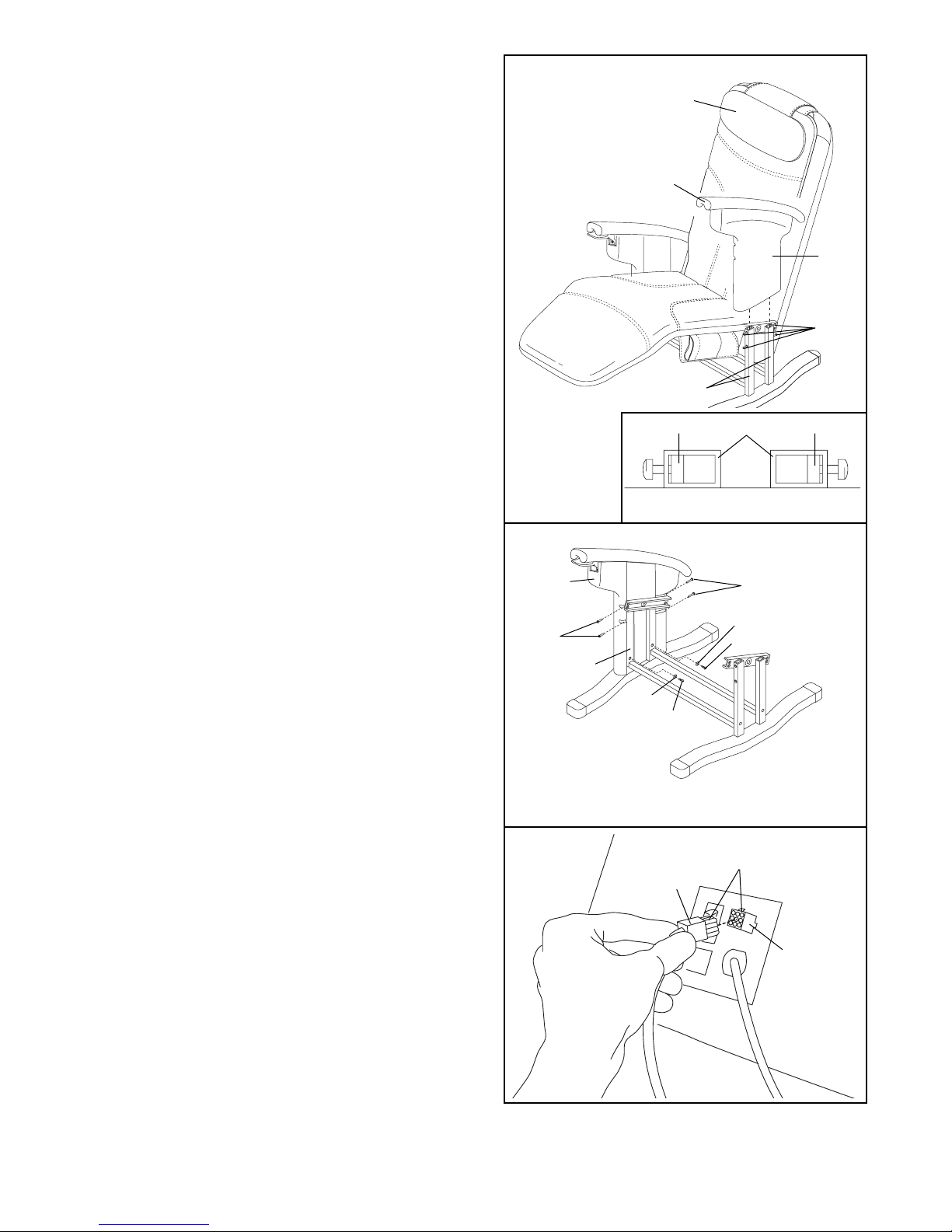
7
4. See the inset drawing. Remove the rubber bands
from the screws. Be sure that the Arm Brackets (31)
inside the tubes on the left side of the Base (1) are
pressed against the indicated sides of the tubes.
Align the posts on the Left Armrest (6) with the tubes
on the Base (1). Slide the Left Armrest onto the
Base. You may need to flex the posts away from the
Left Side Shield (8) to assemble it past the Bracket
Screws (32) in the Base.
Attach the Pillow (13) to the fastener strip.
5. Raise the footrest by pulling on the Footrest Control
Arm (23, not shown). Attach the lower end of the
Right Side Shield (7) to the right side of the Base (1)
with two Arm Cover Screws (35) and two M6
Washers (95).
Attach the lower end of the Left Side Shield (not
shown) in the same manner.
Using the included allen wrench, tighten the four
Bracket Screws (32) in the right side of the Base (1).
Tighten the four Bracket Screws (not shown) in the
left side of the Base in the same manner.
6. Plug the cord from the Hand Control (22) into the
socket on the back of the massage chair. Be sure to
align the indicated tabs.
5
131 31
1
8
6
32
13
32
32
35
95
35
95
7
1
22
Socket
Tabs
6
Note: Parts of the chair are cut away for clarity
4
Page 8
8
HOW TO PLUG IN THE POWER CORD
Your massage chair, like any other type of sophisticated electronic equipment, can be seriously damaged
by sudden voltage changes in your homeÕs power.
Voltage surges, spikes, and noise interference can
result from weather conditions or from other appliances being turned on or off. To decrease the possi-
bility of your massage chair being damaged,
always use a surge suppressor with your massage chair (see drawing 1 below).
Surge suppressors are sold at most hardware stores
and department stores. Use only a single-outlet surge
suppressor that is UL 1449 listed as a transient voltage surge suppressor (TVSS). The surge suppressor
must have a UL suppressed voltage rating of 400
volts or less and a minimum surge dissipation of 450
joules. The surge suppressor must be electrically
rated for 120 volts AC and 15 amps.
This product must be grounded. If it should malfunction or break down, grounding provides a path of
least resistance for electric current to reduce the risk
of electric shock. This product is equipped with a cord
having an equipment-grounding conductor and a
grounding plug. Plug the power cord into a surge
suppressor, and plug the surge suppressor into
an appropriate outlet that is properly installed and
grounded in accordance with all local codes and
ordinances.
This product is for use on a nominal 120-volt circuit,
and has a grounding plug that looks like the plug illustrated in drawing 1. A temporary adapter that looks
like the adapter illustrated in drawing 2 may be used
to connect the surge suppressor to a 2-pole
receptacle as shown in drawing 2 if a properly
grounded outlet is not available.
The temporary adapter should be used only until a
properly grounded outlet (drawing 1) can be installed
by a qualified electrician.
The green-colored rigid ear, lug or the like extending
from the adapter must be connected to a permanent
ground such as a properly grounded outlet box cover.
Whenever the adapter is used it must be held in place
by a metal screw. Some 2-pole receptacle outlet
box covers are not grounded. Contact a qualified
electrician to determine if the outlet box cover is
grounded before using an adapter.
HOW TO TURN ON THE POWER
Make sure the power
switch on the back of the
chair is in the ÒonÓ position.
Next, press the power button on the hand control; an
indicator will light. Note: If
there is a thin sheet of
plastic on the face of the
hand control, remove it.
HOW TO TURN OFF THE POWER
To turn off the power, press the power button on the
hand control. The power indicator will darken. Return
the power switch on the back of the chair to the ÒoffÓ
position.
DANGER: Improper connection
of the equipment-grounding conductor can
result in an increased risk of electric shock.
Check with a qualified electrician or serviceman if you are in doubt as to whether the
product is properly grounded. Do not modify
the plug provided with the productÑif it will
not fit the outlet, have a proper outlet
installed by a qualified electrician.
1
2
Grounded Outlet Box
Grounded Outlet Box
Grounding Plug
Surge Suppressor
Surge Suppressor
Grounding Pin
Adapter
Lug
Metal Screw
Grounded Outlet
Grounding Pin
How to Operate the Massage Chair
Power Button
Page 9
9
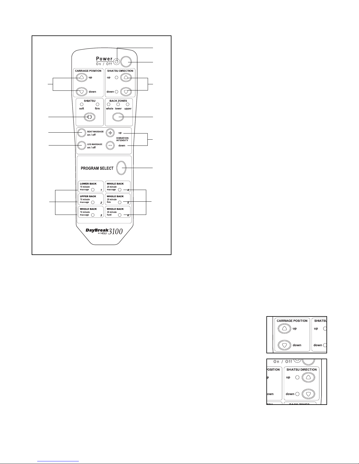
DESCRIPTION OF THE HAND CONTROL
A. Power IndicatorÑLights when the power is on.
B. Power ButtonÑTurns the power on and off.
C. Carriage Position ButtonsÑManually move the
massage mechanism up and down to target specific areas of the back for a localized massage.
D. Shiatsu Direction Buttons and IndicatorsÑThese
buttons control the rotational direction of the massage when the Carriage Position Buttons (C) are
used.
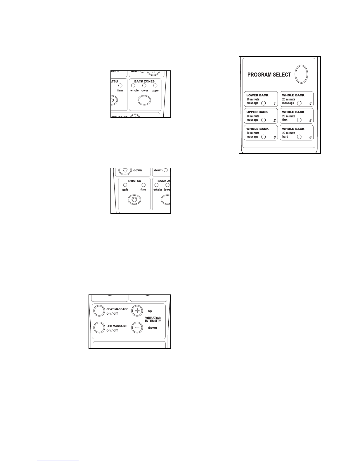
E. Back Zones Button and Whole, Lower, and Upper
IndicatorsÑThe Back Zones button selects the
three massage zones. When the ÒWholeÓ indicator
is lit, the massage mechanism will move up and
down, massaging your entire back. When the
ÒLowerÓ indicator is lit, the massage mechanism
will move up and down, massaging your lower
back. When the ÒUpperÓ indicator is lit, the massage mechanism will move up and down, massaging your upper back.
F. Shiatsu Button and Soft and Firm IndicatorsÑThis
button selects either a soft or firm massage when
you are using the three massage zones.
G. Seat Massage On/OffÑturns the vibration mas-
sage for the seat area on and off.
H. Leg Massage On\OffÑTurns the vibration mas-
sage for the leg area on and off.
I. Up/DownÑincreases or decreases the intensity of
the vibration massage for the seat and leg areas.
J. Program ButtonÑThis button selects the six pro-
grams.
K. Program IndicatorsÑThese will light to show
which program is selected.
FEATURES OF THE MASSAGE CHAIR
The convenient hand control lets you customize the
type of massage you get each time you use the
massage chair. In the manual mode, you can choose
any combination of upper-back, lower-back and
whole-back massage action. If desired, you can also
position the massage carriage to target a specific area
of your back for a specialized massage.
The control also offers six massage programs: 10Minute Lower Back, 10-Minute Upper Back, 10-Minute
Whole Back, 20-Minute Whole Back, 20-Minute Whole
BackÑFirm Massage and 20-Minute Whole
BackÑHard Massage.
HOW TO USE THE MANUAL MODE
When the power is turned on, the hand control will be
in the manual mode. The power indicator should be
the only indicator that is lit.
1. Use the Carriage
Position buttons to
move the massage carriage to the location
you wish to massage.
2. Use the Shiatsu
Direction buttons to
begin massaging your
back. You may want to
try alternating the shiatsu directions during
your massage.
3. If you like, you can use the Carriage Position buttons to move the carriage up and down during the
massage.
C D
EF
I
K
K
J
B
A
G
H
Page 10
10
HOW TO USE THE MASSAGE ZONES
The massage chair also features three massage
zones: upper back, lower back and whole back. The
massage zones are controlled with the Back Zones
button.
1. Press the button once.
The indicator above
ÒwholeÓ will light, activating the whole massage zone. Press the
button again and the
indicator above ÒlowerÓ
will light, activating the
lower massage zone. Press the button again and
the indicator above ÒupperÓ will light, activating the
upper massage zone. Pressing the button again
will end the massage. Press the button once more
to reactivate the ÒwholeÓ massage zone.
2. While you are using
the massage zones,
you can modify the
intensity of the massage by using the
Shiatsu button to
select a soft or firm
massage.
Note: The massage action will automatically stop
if no buttons on the hand control are pressed for
twenty minutes. This applies to both the manual
mode and the massage zones. To restart the mas-
sage action, simply press the power button on the
hand control and select the desired massage option.
HOW TO USE THE VIBRATION ZONES
The massage
chair features
vibration zones
for the seat and
leg area. The
vibration zones
can be turned on
and off by using
the Seat Massage
on/off and Leg Massage on/off buttons. You can regulate the intensity of the vibration zones by pressing
the up and down buttons until you feel the desired
intensity.
HOW TO USE THE MASSAGE PROGRAMS
In addition to the manual mode and massage zones,
the massage chair offers six massage programs.
1. Press the
Program button repeatedly to select
the desired
mode. A program indicator will light to
show which
program is
selected. If
the program
you selected
targets the
lower back,
the lower back zone indicator will also light. If the
program you selected targets the upper back, the
upper back zone indicator will also light. If the program you selected targets the whole back, the
whole back zone indicator will also light.
2. Once you have selected a program, sit back, relax
and enjoy the massage. You can change to a different program at any time.
The massage programs and their functions are:
LOWER BACK 1. This program offers a tenminute lower back massage.
UPPER BACK 2. This program offers a ten-minute
upper back massage.
WHOLE BACK 3. This program offers a tenminute massage of your whole back.
WHOLE BACK 4. This program offers a twentyminute massage of your whole back.
WHOLE BACK 5. This program offers a twentyminute firm massage of your whole back.
WHOLE BACK 6. This program offers a twentyminute hard massage of your whole back.
Note: If no buttons on the hand control are
pressed while a program is running, the massage
chair will shut off once the program is finished.
To restart the massage action, simply press the power
button on the hand control and select the desired
massage option.
Page 11

11
Check the massage chair periodically to make sure
that all parts are properly tightened.
If the hand control does not function properly, check
the following things:
¥ Is the power cord plugged into a 120-volt outlet?
¥ Is the power switch on the back of the chair in the
ÒONÓ position?
¥ Is the hand control properly connected to the mas-
sage chair? (See assembly step 6 on page 7.)
The massage chair can be cleaned with a low-power
hand-held vacuum or a dry cloth. IMPORTANT: Never
use water or solvents to clean the massage chair.
HOW TO USE THE RECLINE CONTROL
To recline the chair, simply pull up on the recline
control on the right armrest. Lean back in the chair
until you have reached the desired position. Release
the recline control.
To return the chair to the upright position, sit up in the
chair and pull up on the recline control. The chair back
will return to the upright position.
HOW TO USE THE FOOTREST
To extend the footrest, pull back on the footrest control
arm on the right side of the chair, until you feel the
control arm lock into place. The footrest will extend.
To lower the footrest, simply push the control arm
forward.
Recline
Control
Footrest
Control Arm
Footrest
Maintenance
Page 12

Part No. 160775 R1099A Printed in USA © 1999 ICON Health & Fitness, Inc.
To order replacement parts, simply call our Customer Service Department toll-free at 1-800-999-3756, Monday
through Friday, 6 a.m. until 6 p.m. Mountain Time (excluding holidays). To help us assist you, please be prepared
to give the following information when calling:
¥ The MODEL NUMBER of the product (WLRX31090)
¥ The NAME of the product (WESLO DAYBREAK 3100 massage chair)
¥ The SERIAL NUMBER of the product (see the front cover of this manual)
¥ The KEY NUMBER and DESCRIPTION of the desired part(s) (see the PART LIST and EXPLODED DRAWING
in the center of this manual).
Ordering Replacement Parts
Page 13

Key No. Qty. Description
1 1 Base
2 1 Seat Frame
3 1 Leg Frame
4 1 Back Frame
5 1 Right Armrest
6 1 Left Armrest
7 1 Right Side Shield
8 1 Left Side Shield
9 1 Right Panel
10 1 Left Panel
11 1 Seat Support
12 10 Support Hook
13 1 Pillow
14 1 Cover Pad
15 1 Chair Back Cover
16 1 Cover
17 1 Back Brace
18 1 Back Cover
19 2 Front Endcap
20 1 Recline Shock
21 1 Shock Actuator
22 1 Hand Control
23 1 Footrest Control Arm
24 1 Leg Link
25 1 Link Arm
26 6 Cotter Pin
27 6 Hairpin Cotter
28 1 Shock Nut
29 3 Set Screw
30 2 Seat Pin
31 4 Arm Bracket
32 10 Bracket Screw
33 4 Arm Screw
34 4 Arm Washer
35 4 Arm Cover Screw
36 4 Pad Frame Screw
37 4 Back Cover Screw
38 2 Straight Massage Arm
39 2 Rear Wheel
40 4 Short Massage Spacer
41 4 Long Massage Spacer
42 4 Massage Motor Nut
43 1 Massage Motor
44 2 Roll Pin
45 2 Short Massage Spring
46 1 Right Bent Massage Arm
47 1 Left Bent Massage Arm
48 4 Massage Roller
Key No. Qty. Description
49 4 Massage Screw
50 18 Roller Washer
51 8 Roller Bolt
52 6 Roller Nut
53 4 Spring Pin
54 1 Circuit Board
55 4 Board Spacer
56 4 Board Nut
57 4 Board Screw
58 2 Flat-sided Washer
59 4 Brace Washer
60 4 Brace Nut
61 2 Brace Screw
62 6 Wire Tie
63 2 Limit Switch
64 1 Four-wire Coil
65 2 Rear Wheel Axle
66 2 Jumper Wire
67 1 Power Cord
68 1 Power Switch
69 1 Fuse
70 2 Wire Mount
71 4 Bearing Screw
72 1 Sensor
73 6 Sensor Screw
74 6 Sensor Nut
75 1 Sensor Bracket
76 1 Motor
77 1 Fan
78 1 Drive Capacitor
79 1 Belt
80 4 Star Washer
81 4 Motor Washer
82 4 Motor Screw
83 1 Lift Assist Shock
84 4 Endcap Screw
85 2 Rear Endcap
86 2 Long Massage Spring
87 2 Seat Frame Endcap
88 1 Sensor Wire
89 1 Shiatsu Capacitor
90 1 Cover Bracket
91 1 Upper Switch Cover Bracket
92 1 Lower Switch Cover Bracket
93 3 Tec Screw
94 2 M8 Nut
95 4 M6 Washer
# 1 UserÕs Manual
Note: Ò#Ó indicates a non-illustrated part. Specifications are subject to change without notice. To order replacement
parts, see the back cover of this manual.
Part ListÑModel No. WLRX31090
R1099A
 Loading...