

WXR 3
GB Translation of the original instructions

English
Technical Data | Safety information | Menu navigation |
Care and maintenance | Warranty
DEGBESFRITPTNLSVDKFIGRCZ TRPL
35
HU
SKSLEELTLVBG
RO
HRRU
41 2
USB COM 143COM 2
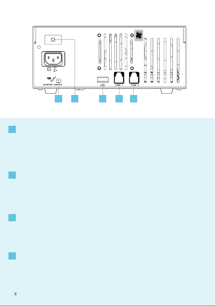
DE Potentialausgleich
1
GB Equipotential bonding
ES Equipotencial
FR Compensation de potentiel
IT Compensazione di potenziale
PT Equilíbrio do potencial
NL Potentiaalvereffening
SV Potentialutjämning
DK Spændingsudligning
DE Netzsicherung
2
GB Mains fuse
ES Fusible
FR Fusible secteur
IT Protezione della rete
PT Fusível de rede
NL Netbeveiliging
SV Nätsäkring
DE USB-Schnittstelle
3
GB USB port
ES Interfaz USB
FR Interface USB
IT Interfaccia USB
PT Interface USB
NL USB-poort
SV USB-port
DE Schnittstelle
4
GB Interface
ES Interfaz
FR Interface
IT Interfaccia
PT Interface
NL Interface
SV Gränssnitt
FI Potentiaalin tasaus
GR Εξίσωση δυναμικού
TR Potansiyel dengelemesi
CZ Vyrovnání potenciálů
PL Wyrównanie potencjału
HU Feszültségkiegyenlítő hüvely
SK
Zásuvka vyrovnania potenciálov
SL Vtičnica za izenačevanje
potenciala
DK Netsikring
FI Verkkosulake
GR Ηλεκτρική ασφάλεια δικτύου
TR Şebeke sigortası
CZ Síťová pojistka
PL Bezpiecznik sieciowy
HU Hálózati biztosíték
SK Sieťová poistka
DK USB-port
FI USB-liitäntä
GR Θύρα διεπαφής USB
TR USB arabirim
CZ Rozhraní USB
PL Złącze USB
HU USB csatlakozó
SK Rozhranie USB
DK Interface
FI Liittymä
GR Θύρα διεπαφής
TR Arabirim
CZ Rozhraní
PL Interfejs
HU Interfész
SK Rozhranie
EE Potentsiaalide ühtlustuspuks
LV Potenciālu izlīdzināšanas
pieslēgvieta
LT Potencialo išlyginimo įvorė
BG Изравняване на
потенциалите
RO
Egalizare de potențial
HR Izjednačavanje potencijala
RU Выравнивание потенциалов
SL Omrežna varovalka
EE Võrgukaitse
LV Elektriskā tīkla drošinātājs
LT Tinklo saugiklis
BG Мрежов предпазител
RO Siguranţă de reţea
HR Mrežni osigurač
RU Предохранитель электросети
SL Vmesnik USB
EE USB-liides
LV USB pieslēgvieta
LT USB sąsaja
BG USB-интерфейс
RO Interfaţă USB
HR Sučelje USB
RU Интерфейс USB
SL Vmesnik
EE Liides
LV Saskarne
LT Sąsaja
BG Интерфейс
RO Interfaţă
HR Sučelje
RU Интерфейс
6
Air Vac Pick Up
¬
65 6
Pick
Up 1
¬
Pick Up
6
Pick
Up 2
7
UP /
DOWN
5
6
7
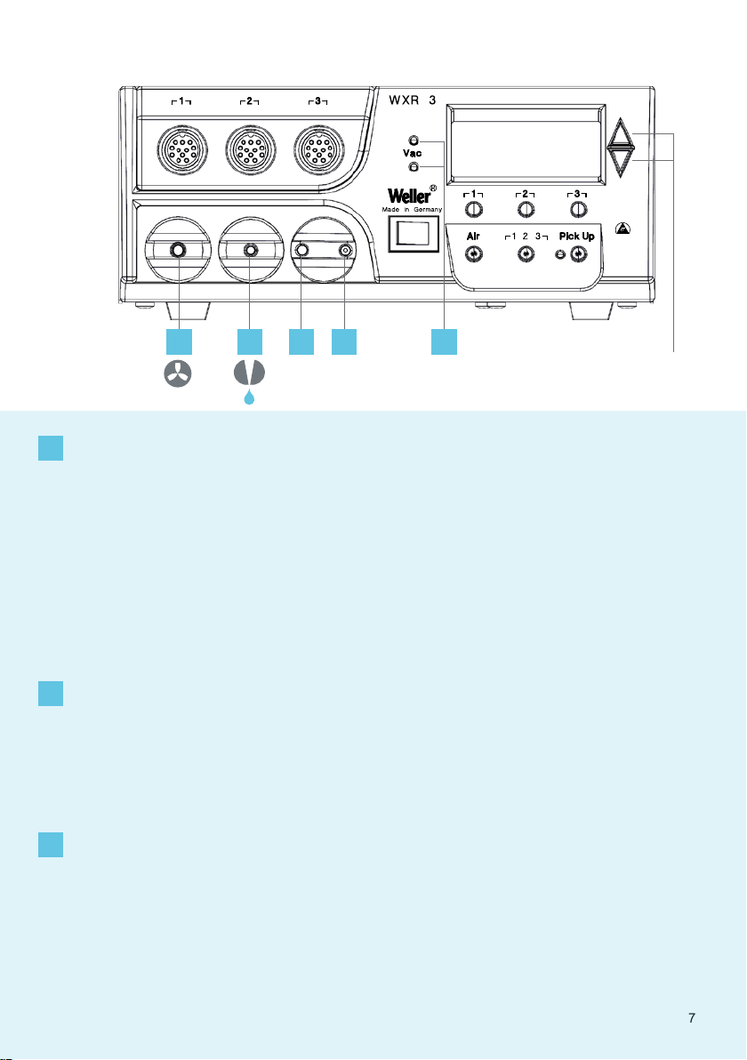
Heißluftkolben
Air connection nipple for
GB
hot air tools
Boquilla de conexión del
ES
aire para el soldador de
aire caliente
Raccord de connexion
FR
d‘air pour fers à air chaud
Nipplo di collegamento aria
IT
per saldatore ad aria calda
Niples de ligação de ar para
PT
ferros de soldar por ar quente
Luchtaansluitnippel voor
NL
heteluchtbout
Luftanslutningsnippel för
SV
hetluftspenna
DE Vakuumanschluss
GB Vacuum connection
ES Toma de vacío
FR Raccord de vide
IT Collegamento per vuoto
PT Ligação de vácuo
NL Vacuümaansluiting
SV Vakuumanslutning
DE LED Vakuum
GB Vacuum LED
ES LED Vacío
FR LED vide
IT LED Vuoto
PT LED do vácuo
NL LED vacuüm
SV Lysdiod vakuum
Luftanschlussnippel für
DE
Lufttilslutningsnippel til
DK
varmluftskolbe
Ilmaliitäntänippa ku-
FI
umailmakolville
Στόμιο σύνδεσης αέρα για
GR
έμβολο θερμού αέρα
Sıcak hava pistonu için
TR
hava bağlantı nipeli
Šroubovací přípojka vzdu-
CZ
chu pro horkovzdušný píst
Šroubovací přípojka vzdu-
PL
chu pro horkovzdušný píst
Levegőcsatlakozó a
HU
forrólevegős páka számára
Prípojka vzduchu pre
SK
teplovzdušnú rúčku
Priključni nastavek spaj-
SL
kalnika za vroči zrak
DK Vakuumtilslutning
FI Tyhjiöliitäntä
GR Σύνδεση κενού
TR Vakum bağlantısı
CZ Přípojka vakua
PL Przłącze próżni
HU Vákuumcsatlakozó
SK Prípojka vákua
SL Priključek za podtlak
DK LED vakuum
FI Tyhjiön LED
GR LED κενού
TR Vakum LED'i
CZ LED vakuum
PL Dioda LED próżni
HU Vákuum LED
SK LED-dióda: podtlak
Õhuühenduse nippel
EE
kuuma õhu kolvidele
Gaisa pieslēguma nipelis
LV
karstā gaisa lodāmuram
Karšto oro stūmoklio oro
LT
jungties antgalis
Нипел за присъдиняван
BG
на въздух за поялник с
горещ въздух
Niplu de racordare pentru
RO
letconul cu aer cald
Nazuvica za priključak zra-
HR
ka za lemilo na vrući zrak
Подключение воздуха
RU
ниппель для горячей
пайки воздуха
EE Vaakumühendus
LV Vakuuma pieslēgums
LT Vakuumo jungtis
BG Съединителен елемент за
вакуум
RO Racord pentru vid
HR Vakuumski priključak
RU Вакуумное соединение
SL LED-dioda podtlaka
EE LED vaakum
LV Vakuuma LED diode
LT LED vakuumas
BG Вакуум LED
RO LED vid
HR LED vakuum
RU Светодиодный индикатор
вакуума
7
4
2 1
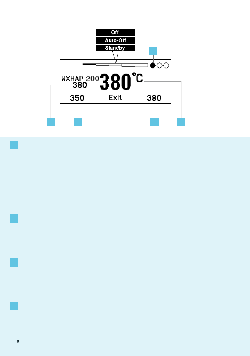
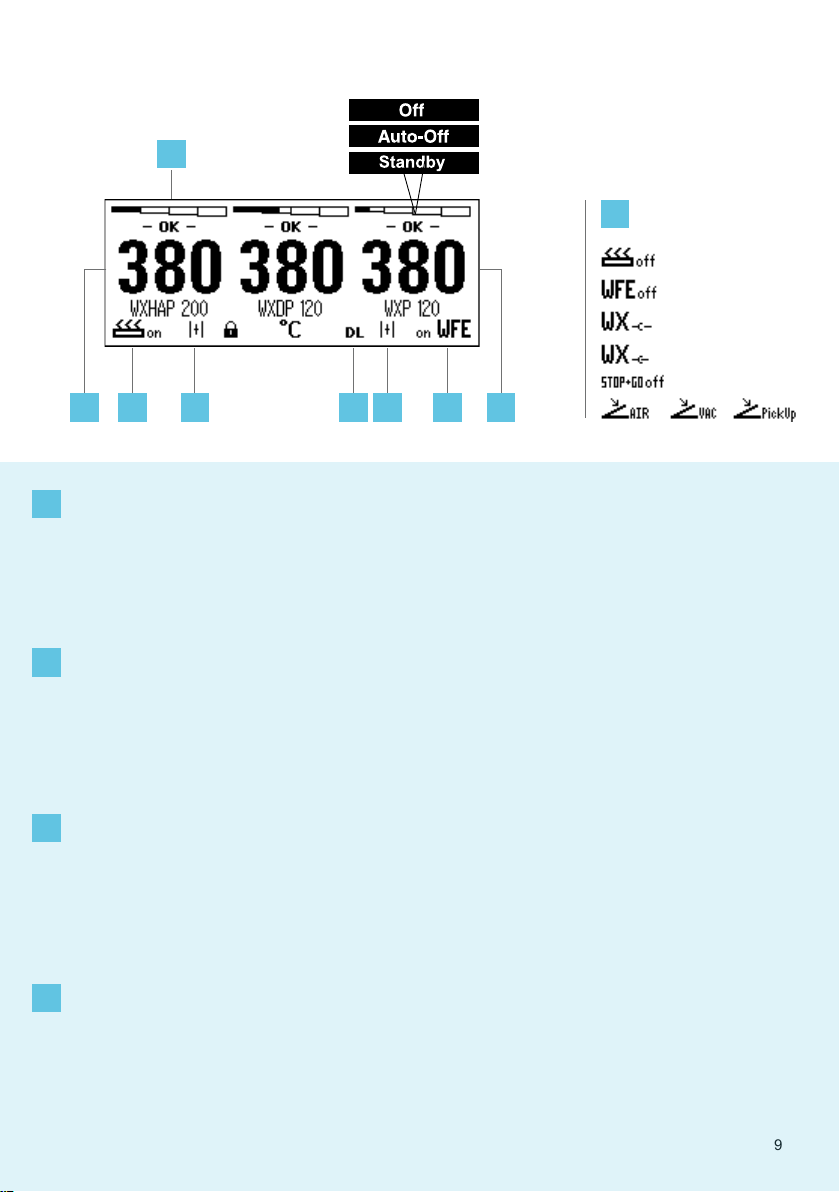
Isttemperatur / Solltemperatur
DE
1
Actual temperature / nominal
GB
temperature
Temperatura real / temperatu-
ES
ra de referencia
Température réelle / tempéra-
FR
ture de consigne
Temperatura reale / tempera-
IT
tura nominale
Temperatura real / temperatu-
PT
ra nominal
Werkelijke temperatuur /
NL
gewenste temperatuur
Faktisk temperatur / börtem-
SV
peratur
DE Solltemperatur
2
GB Nominal temperature
ES Temperatura de referencia
FR Température de consigne
IT Temperatura nominale
PT Temperatura nominal
NL Gewenste temperatuur
SV Börtemperatur
DE Festtemperatur
3
GB Fixed temperature
ES Temperatura ja
FR Température xe
IT Temperatura ssa
PT Temperatura xa
NL Vaste temperatuur
SV Fast temperatur
Faktisk temperatur / nominel
DK
temperatur
Todellinen lämpötila / ohje-
FI
lämpötila
Πραγματική θερμοκρασία /
GR
ονομαστική θερμοκρασία
Fiili sıcaklık / nominal sıcaklık
TR
Skutečná teplota / nominal
CZ
sıcaklık
Temperatura rzeczywista /
PL
temperatura zadana
Mért hőmérséklet / temperatu-
HU
ra hőmérséklet
Skutočná teplota /
SK
požadovaná teplota
DK Nominel temperatur
FI Ohjelämpötila
GR Ονομαστική θερμοκρασία
TR Nominal sıcaklık
CZ Nominal sıcaklık
PL Temperatura zadana
HU Temperatura hőmérséklet
SK Požadovaná teplota
DK Fast temperatur
FI Kiinteä lämpötila
GR Σταθερή θερμοκρασία
TR Sabit sıcaklık
CZ Stanovená teplota
PL Temperatura stała
HU Rögzített hőmérséklet
SK Pevná teplota
33
Dejanska temperatura /
SL
želena temperatura
Tegelik väärtus / sihttempe-
EE
ratuur
Faktiskā temperatūra / vēlamā
LV
temperatūra
Esama temperatūra / nustaty-
LT
toji temperatūra
Действителна температура /
BG
Зададена температура
Temperatura efectivă / Tem-
RO
peratura nominală
Stvarna temperatura / Zadana
HR
temperatura
Фактическая температура /
RU
Заданная температура
SL Želena temperatura
EE Sihttemperatuur
LV Vēlamā temperatūra
LT Nustatytoji temperatūra
BG Зададена температура
RO Temperatura nominală
HR Zadana temperatura
RU Заданная температура
SL Stalna temperatura
EE Püsitemperatuur
LV Noteiktā temperatūra
LT Fiksuotoji temperatūra
BG Непроменлива температура
RO Temperatura xă
HR Fiksna temperatura
RU Фиксированная температура
DE Aktiver Kanal
4
GB Active channel
ES Canal activo
FR Canal actif
IT Canale attivo
PT Canal ativo
NL Actief kanaal
SV Aktiv kanal
8
DK Aktiv kanal
FI Aktivoitu kanava
GR Ενεργό κανάλι
TR Aktif kanal
CZ Aktivní kanál
PL Aktywny kanał
HU Aktív csatorna
SK Aktívny kanál
SL Aktivni kanal
EE Aktiivne kanal
LV Aktīvais kanāls
LT Aktyvus kanalas
BG Активен канал
RO Canal activ
HR Aktivni kanal
RU Aктивный канал
8
1 5
5 7 66
COM 1 COM 2
5
1
DE Schnittstelle COM 1 / COM 2
5
GB Interface COM 1 / COM 2
ES Interfaz COM 1 / COM 2
FR Interface COM 1 / COM 2
IT Interfaccia COM 1 / COM 2
PT Interface COM 1 / COM 2
NL Interface COM 1 / COM 2
SV Gränssnitt COM 1 / COM 2
WFV 60A
6
DE Zustandsanzeige
GB Status indication
ES Indicación del estado
FR Indication d'état
IT Indicatore di stato
PT Indicação de status
NL Statusweergave
SV Statusvisning
DATA LOGGER (DL) aktiv
DE
7
8
DATA LOGGER (DL) active
GB
DATA LOGGER (DL) activo
ES
DATA LOGGER (DL) actif
FR
DATA LOGGER (DL) attivo
IT
REGISTO DE DADOS (DL)
PT
activo
DATA LOGGER (DL) actief
NL
DATA LOGGER (DL) aktiv
SV
DATA LOGGER (DL) aktiv
DK
2 CH 1, 2, 3
Indikator Schaltausgang
DE
Switching output indicator
GB
Indicador salida de conexión
ES
Indicateur sortie de commutation
FR
Indicatore uscita di commuta-
IT
zione
Indicador da saída de comu-
PT
tação
Indicator schakeluitgang
NL
DK Interface COM 1 / COM 2
FI Liittymä COM 1 / COM 2
GR Θύρα διεπαφής COM 1/ COM 2
TR Arabirim COM 1 / COM 2
CZ Rozhraní COM 1 / COM 2
PL Interfejs COM 1 / COM 2
HU Interfész COM 1 / COM 2
SK Rozhranie COM 1 / COM 2
DK Statusindikator
FI Tilanneilmaisin
GR Ενδειξη προόδου
TR Durum göstergesidir
CZ Zobrazení stavu
PL Wyświetlacz stanu
HU Állapot kijelző
SK Zobrazenie stavu
DATA LOGGER (DL) aktivoitu
FI
DATA LOGGER (DL) ενεργό
GR
VERİ GÜNLÜKLEYİCİ (DL) aktif
TR
DATA LOGGER (DL) aktivní
CZ
DATA LOGGER (DL) aktywny
PL
DATA LOGGER (DL - adatnap-
HU
lózás) aktív
DATA LOGGER (DL) aktívny
SK
DATA LOGGER (DL) je aktiviran
SL
DATA LOGGER (DL) on aktiivne
EE
Indikator kopplingsutgång
SV
Indikator koblingsudgang
DK
Kytkentälähdön ilmaisin
FI
Δείκτης επαφής εξόδου
GR
Devre çıkışı göstergesi
TR
Indikátor spínacího výstupu
CZ
Wskaźnik wyjścia
PL
przełączającego
Kapcsolókimenet indikátor
HU
Indikátor spínacieho výstupu
SK
SL Vmesnik COM 1 / COM 2
EE Liides COM 1 / COM 2
LV Saskarne COM 1 / COM 2
LT Sąsaja COM 1 / COM 2
BG Интерфейс COM 1 / COM 2
RO Interfaţă COM 1 / COM 2
HR Sučelje COM 1 / COM 2
RU Интерфейс COM 1 / COM 2
SL Prikaz stanja
EE Olekuekraan
LV Stāvokļa displejs
LT Būklės indikatorius
BG Индикация на състоянието
RO Aşajul de stare
HR Prikaz stanja
RU Индикация состояния
DATU REĢISTRĒTĀJS (DR) ir
LV
ieslēgts
Aktyvintas duomenų registravi-
LT
mo įtaisas DATA LOGGER (DL)
DATA LOGGER (DL) активна
BG
DATA LOGGER (DL) activ
RO
DATA LOGGER (DL) aktiviran
HR
РЕГИСТРАТОР ДАННЫХ
RU
(РД) активирован
Indikator izhoda
SL
Lülitusväljundi indikaator
EE
Slēguma izejas indikators
LV
LT Indikatoriaus jungimo išvadas
BG Включване индикатор изход
RO Indicator ieşire de comutare
HR Indikator prekidača za izlaz
Индикатор коммутируемого
RU
выхода
9

For your safety
Thank you for the condence you have shown in
buying this device.
The device has been manufactured in accordance
with the most rigorous quality standards which ensure that it operates perfectly.
Read these instructions and the
accompanying safety information
carefully before starting up the device
and starting work with the device.
Keep these instructions in a place that is accessible to all users.
Safety information
For safety reasons, children
and youths under the age of 16,
as well as persons who are not
familiar with these operating inst-
ructions, may not use the device.
Children should be supervised in
order to ensure that they do not
play with the tool.
Warning! Electrical shock
Connecting the control unit incorrectly poses a risk of injury due to electric shock and
can damage the device.
Carefully read the attached safety information, the safety information accompanying these
operating instructions as well as the operating instructions for your control unit before putting
the control unit into operation and observe the safety precautions specied therein.
Only connect WELLER WX tools.
Never use the USB port as a power supply for third-party devices.
If the device is faulty, active electrical conductors may be bare or the PE conductor
may not be functional.
Repairs must always be referred to a Weller-trained specialist.
If the electrical tool‘s power supply cord is damaged, this must be replaced with a specially
prefabricated power supply cord available through the customer service organisation.
These instructions contain important information
which will help you to start up, operate and service
the device safely and correctly as well as to eliminate
simple faults and malfunctions yourselves.
The device has been manufactured in accordance
with state-of-the-art technology and acknowledged regulations concerning safety.
There is nevertheless the risk of personal injury and
damage to property if you fail to observe the safety
information set out in the accompanying booklet and
the warnings given in these instructions.
This device is not intended
for use by persons (including
children) with limited physical,
sensory or mental aptitude, or
by persons who lack knowledge
or experience in handling the
device.
EN
Warning! Risk of burns
Risk of burns from the soldering tool while the control unit is operating. Tools may
still be hot long after they have been switched off.
Always place the soldering tool in the safety rest while not in use.
Only connect the vacuum and hot air at the designated points.
Do not direct hot air soldering tools at people or inammable objects.
35

For your safety
Warning! Fire and explosion hazard!
Hot tools represent a re hazard
EN
Specied Conditions Of Use
Always place the soldering tool in the safety rest while not in use.
Do not direct hot air soldering tools at people or inammable objects.
Keep explosive and ammable objects well away from the device.
Do not cover the device.
Supply unit for WELLER WX soldering tools.
Use the repair station only for the purpose indica-
ted in the operating instructions of soldering and
desoldering under the conditions specied herein.
Flammable gases and liquids may not
be extracted.
The device may only be used with
correctly tted and suitable lter
cartridges.
Replace lter cartridges when full.
Only use the device indoors. Protect against mois-
ture and direct sunlight.
Intended use of the soldering station/ desoldering
station also includes the requirement that you
adhere to these instructions,
observe all other accompanying documents,
comply with national accident prevention
guidelines applicable at the place of use.
The manufacturer will not be liable for unautho-
rised modications to the device.
User groups
Due to differing degrees of risk and potential hazards, several work steps may only be performed by
trained experts.
Work step User groups
Default soldering parameters Specialist personnel with technical training
Replacing electrical replacement parts Electricians
Default maintenance intervals Safety expert
Operation
Filter change
Operation
Filter change
Replacing electrical replacement parts
Non-specialists
Technical trainees under the guidance and supervision
of a trained expert
36

For your safety
Starting up the device
Caution!
Please adhere to the operating instructions of
the connected devices.
Put the tool into operation as described in the
chapter „Placing into operation“.
Check to see if the mains voltage matches the ratings on the nameplate.
Soldering and desoldering
Carry out soldering work as directed in the operating instructions of your connected soldering tool.
Handling the soldering tips
Coat the selective and tinnable soldering tip with
solder when heating it up for the rst time. This
removes oxide coatings which have formed
during storage and impurities from the soldering
tip.
Make sure that the soldering tip is well coated
with solder during breaks between soldering work
and prior to storage of the device.
Do not use aggressive uxing agents.
Always make sure that the soldering tips are
tted properly.
Select as low a working temperature as possible.
Select the largest possible soldering tip shape for
the application.
Rule of thumb: the soldering tip should be roughly
as large as the soldering pad.
Coat the soldering tip well with solder to ensure
Make sure the machine is switched off before
plugging in.
After switching on the device, the microprocessor
carries out a self- test and reads out the values of
the parameters stored in the tool.
The set-point temperature and xed temperatures
are stored in the tool. The actual temperature
value increases to the set-point temperature (=
soldering tool is heated up).
that there is efcient heat transfer between the
soldering tip and the soldering area.
Prior to extended breaks between soldering work,
switch off the soldering system or use the Weller
function to reduce the temperature when the
soldering equipment is not in use.
Coat the tip with solder prior to storage if you do
not intend to use the soldering iron for an
extended period of time.
Apply solder directly to the soldering area, not to
the soldering tip.
Change the soldering tips using the designated
tool.
Do not apply mechanical force to the soldering
tip.
Notice
The control units have been adapted to hold a
medium-sized soldering tip. Discrepancies may
occur if the tip is changed or a different shaped
tip is used.
EN
Overload cut-out
To avoid overloading the station, power output is
automatically reduced in the event of an overload.
37

For your safety
Equipotential bonding
EN
a
b
c
d
Carrying out a rmware update
Notice
The station must not be switched off while the
rmware update is running.
Care and maintenance
Warning!
Before doing any work on the machine, pull the plug out of the socket.
Warning!
Use original replacement parts only.
Warning! Risk of burns
Only replace solder tips when cold
Replace and clean suction nozzles
only when hot and using the suitable
tool
Only replace hot air nozzles using
the suitable tool
Only clean or replace solder
collection tubes when cold
Four variants are possible by connecting the 3.5 mm jack socket
differently:
a Hard-grounded supplied without plug.
b Equipotential
bonding
c Floating with plug
d Soft-grounded with plug and soldered resistor. Ground-
Switch off station 1.
2. Insert the memory stick into the USB port.
Switch on station 3.
The rmware update is performed automatically.
If you have a more already installed more recent
rmware on your station, this will not be changed.
Clean the operator panel, if dirty, using a suitable
cleaning cloth.
Filter change
To ensure that the ltration system functions properly, the lter must be replaced as follows
with plug, equaliser at centre contact.
ed through selected resistor.
at least once a year or
when indicated or
as per maintenance schedule
Contaminated lters must be treated as special
waste.
Dispose of replaced equipment parts, lters
or old devices in accordance with the rules
and regulations applicable in your country.
Wear suitable protective gear.
38

Parameter menu
Standby Temp. Menu access Tool parameters
The soldering tools have a usage detection device
(sensor) in the handle which automatically initiates
cooling to Standby temperature when the solde-
ring tool is not in use.
Standby time (temperature deactivation) Menu access Tool parameters
When the soldering tool is not in use, the tem-
perature is reduced to Standby temperature on
expiration of the set Standby time. The display
reads „Standby“.
Press control key to exit Standby mode. The
sensor integrated tool detects the change in state
and deactivates Standby mode as soon as the tool
is moved.
Option Description
OFF standby time is deactivated (factory
setting)
1-999 min standby time, individually adjustable
--- The tool is not supported
AUTO OFF time (automatic switch-off time) Menu access Tool parameters
When the soldering tool is not in use, the soldering
tool heater is switched off when the AUTO OFF
time expires.
Temperature deactivation is performed indepen-
dently of the set standby function. The actual
temperature is indicated and serves as a residual
heat display. The display reads „AUTO OFF“.
Option Description
OFF AUTO OFF function is deactivated
(factory setting)
1-999 min AUTO-OFF time, can be set indivi-
dually.
Sensitivity Menu access Tool parameters
Option Description
low Non-sensitive – Reacts to heavy (long) movement
normal standard (factory setting)
high Sensitive - Reacts to light (short) movement
--- The tool is not supported
EN
Max. hot air duration WXHAP Menu access Tool parameters
The on-time of the hot air ow of the WXHAP can
be limited in increments of 1 to between 0 and 300
sec. The factory default is 0 s („OFF“), i.e. air ows
only as long as the button on the hot air tool or the
optional footswitch is pressed.
Option Description
OFF No duration dened
(factory setting)
1-300 s Individually adjustable
Offset (Temperature-Offset) Menu access Tool parameters
The actual soldering-tip temperature can be
adapted by entering a temperature offset around ±
40 °C (± 72 °F).
39

Parameter menu
Perform. Mode Menu access Tool parameters
The function determines the heating characteris-
EN
tics of the soldering tool to achieve the set tool
temperature.
Option Description
standard adapted (medium) heating (factory
setting)
min. slow heating
max. rapid heating
Button lock WXHAP Menu access Tool parameters
This function can be used to adjust the factory
button presets of the WXAHP tool.
Option Description
OFF –
ON The WXHAP is switched on the rst
time the button is pressed and switched
off the next time the button is pressed.
Process window Menu access Tool parameters
The temperature range set in the process window
determines the signal response of the oating
switching output.
Notice
On tools with an LED ring light (e.g. WXDP 120),
the process window denes the illumination
characteristics of the LED ring light.
If the LED is continuously illuminated, this means
that the preselected temperature has been
reached or that the temperature is within the
predetermined process window.
A ashing LED indicates that the system is
heated or that the temperature is outside the
process window.
Language Menu access Station parameters
CHN
中文
DEN Dansk
ENG English
ESP Español
FIN Suomi
FRA Français
GER Deutsch
HUN Magyar
ITA Italiano
POR Português
RUS Pусский
SWE Svenska
TUR Türkçe
JPN
日本語
POL Polski
KOR
CZE Český
한국말
Temperature version °C/°F (temperature units) Menu access Station parameters
Option Description
° C Celsius
° F Fahrenheit
40

Parameter menu
Password (lock function) Menu access Station parameters
After switching the lock function on, only the xed
temperature keys can be operated on the solde-
ring station. All other settings are disabled until the
repair station is unlocked again.
Notice
If you want only one temperature value to be
selectable, the control keys xed temperature
keys) must be set to the same temperature value.
Locking the soldering station
Set the desired three-digit locking code (between
001 and 999) using the UP / DOWN buttons.
Conrm the code with the Enter key.
The lock is active (the display shows a lock
symbol).
Unlocking the soldering station
1. Call up the parameter menu. If the lock function
is active, the password menu item opens
automatically. Three stars (***) are shown on
the display.
2. Set the three-digit locking code using the UP /
DOWN buttons.
3. Conrm the code with the Enter key.
Forgotten code?
Please contact our Customer
Service: technical-service@
weller-tools.com
Single-channel display Menu access Station parameters
To obtain more straightforward readings, the
display mode from can switched from 3-channel
display to 1-channel display.
If single-channel display is selected, the device
does not reset automatically to 3-channel display
after setting the temperature of a tool channel.
The display mode can be reset using ┌ 2 ┐.
Option Description
OFF Automatic reset to 3-channel display
(factory setting)
ON No automatic reset to 3-channel
display
Vacuum pre-feed Menu access Station parameters
In order to prevent the pump from starting pre-
maturely or to ensure a dened soldering-joint
preheating time, it is possible to set an ON delay.
Option Description
0 sec OFF: vacuum pre-feed function is
OFF (factory setting)
1-10 sec ON: vacuum pre-feed time, indivi-
dually
EN
Vacuum run-on Menu access Station parameters
To prevent the desoldering iron from becoming
clogged, it is possible to set a vacuum run-on time.
Option Description
0 sec OFF: vacuum run-on function is OFF
(factory setting)
1-10 sec ON: vacuum run-on time, individually
adjustable
41

Parameter menu
Pressure gauge threshold Menu access Station parameters
This function can be used to dene the mainte-
EN
nance interval of the desoldering tool. This is done
by setting the value in mbar at which the electric
pressure gauge issues a warning signal when the
intake system is contaminated (LED of the vacuum
pump switches from green to red). The set value is
dependent on the suction nozzles used.
Adjustable -400 mbar to -800 mbar
factory setting -600 mbar
1. The system (tips and lter) must be free.
2. Select the menu item „Pressure gauge
threshold“ in the menu.
3. Set the „Pressure gauge threshold“ pressure
value with the UP or DOWN button. The status
LED switches back and forth between red and
green. Use the UP button to increase vacuum
by 50 to 80 mbar, then pinch the vacuum tube
and check whether the LED switches from
green to red.
4. Adopting the set change.
Interface COM 1 / 2 Menu access Station parameters
Option Description
RS232 Serial communication with PC or other compatible Weller devices (factory setting).
Air The COM 1 port is congured as a foot switch input for activating the air ow.
Vac The COM 1 port is congured as a foot switch input for activating the vacuum.
PickUp The COM 1 port is congured as a foot switch input for activating the PickUp vacuum.
Stop&Go The COM 1 port is used to drive an optional optotransmitter so that a KHE-P control
unit can be activated via an optical bre.
The output is activated when a tool is used. In addition, the oating switched output is
closed. The output is off in the Standby, Auto Off or Off positions, or if no tool is inserted.
Floating switching output 1 Menu access Station parameters
Floating switching output 1 is located at the COM 1 port.
Option Description
OFF (factory setting)
ZeroSmog The oating switching output is closed when a tool is in use. Selected Zero Smog
extraction systems can be connected using an optional adaptor (WX HUB). The rear
RS 232 port remains functional.
Switching output is open in the Standby, Auto Off or Off positions, or if no tool is inser-
ted.
42
Notice
If the COM 1 port is also congured for „Stop&Go“ use, the „Filter full“
message is evaluated by the WX HUB and, where applicable, a
message appears on the display .

Parameter menu
Floating switching output 2 Menu access Station parameters
Floating switching output 2 is located at the COM 2 port.
Option Description
OFF (factory setting)
CH 1 Tool channel 1 controls the switching output
CH 1+2 Tool channel 1 + 2 controls the switching output
CH 1+2+3 Tool channel 1 + 2 + 3 controls the switching output
Notice
If the robot is at working temperature, the display will show – ok –.
Technical Data
Repair station WXR 3
Dimensions L x W x H 273 x 235 x 102 mm
(10,75 x 9,25 x 4,02 inch)
Weight ca. 6,7 kg
Mains supply voltage 230 V, 50 Hz T0053500699
120 V, 60 Hz WXR 3
100 V 50/60 Hz T0053500199
Power consumption 420 W (600 W)
Safety class I, antistatic housing
Fuse Overcurrent release 230 V; 2,0 A
Temperature range Celsius: 100 - 450°C (550°C)
Temperature accuracy ± 9 °C (± 17 °F) Tool dependent (WXHAP ±30 °C / ±80 °F)
Temperature stability ± 2 °C (± 4 °F)
Equipotential bonding Via 3.5 mm pawl socket on back of unit
Display 240 x 88 dots / Backlighting
USB port The control unit comes with a front-side USB port for installing rmware
Pump (Intermittent mode
(30/30) s)
Additional vacuum pump Max. vacuum0,5 bar
III, Soldering tool
120 V; 4,0 A
Fahrenheit: 200 - 850°F (999°F)
Controllable temperature range is tool-dependent
updates, conguration and monitoring.
Max. vacuum 0,7 bar
Max. delivery rate 18 l/min
Max. hot air 15 l/min
Max. delivery rate 1,7 l/min
EN
43

Error messages and error clearance
Message/symptom Possible cause Remedial measures
EN
Display: „- - -
No display function (display
OFF)
No vacuum at desoldering tool
Insufcient vacuum at desolde-
ring tool
Hot air tool has no air
Tool has not been detected
Tool defective
No mains supply voltage Turn on mains power switch
Vacuum not connected
Desoldering nozzle clogged
Pump faulty
Filter cartridge on desoldering
tool full
Main lter full
Air hose not connected
Main lter full
Check connection of tool to
device
Check connected tool
Check mains supply voltage
Check device fuse
Connect vacuum hose to
vacuum connection
Service desoldering nozzle
using cleaning tool
Change lter cartridge on
desoldering tool full
Change the main lter element
on the soldering station
Connect or check air hose
Change main lter cartridge on
soldering station
Symbols
Caution!
Soldering
Read the operating instructions!
44
Before performing work of any kind
on the unit, always disconnect the
power plug from the socket.
ESD-compatible design and ESDcompatible workstation
Equipotential bonding
CE mark of conformity
Fuse
Safety transformer
Desoldering
Hot air
Disposal
Do not dispose of electric tools together
with household waste material! In
observance of European Directive
2012/19/EU on waste electrical and
electronic equipment and its implementation in accordance with national law,
electric tools that have reached the end
of their life must be collected separately
and returned to an environmentally
compatible recycling facility.
Dispose of replaced equipment parts,
lters or old devices in accordance with
the rules and regulations applicable in
your country.

Original declaration of conformity
Repair station WXR 3
Tool WXHAP 200, WXDP 120, WXDV 120, WXP 65, WXP 120,
We hereby declare that the products described herein comply with the following guidelines:
2011/65/EU (RoHS), 2004/108/EG, 2006/42/EG
Applied harmonised standards:
DIN EN 55014-1: 2012-05 DIN EN 60335-1: 2012-10
DIN EN 55014-2: 2009-06 DIN EN 60335-2-45: 2012-08
DIN EN 61000-3-2: 2010-03 / 2011-06 DIN EN 62233: 2008-11 / 2009-04
DIN EN 61000-3-3: 2014-03 DIN EN 50581:2013-02
Besigheim, 2014-07-18
T. Fischer S. Hofmann
Technical director Managing director
Authorised to compile technical documentation.
Weller Tools GmbH
Carl-Benz-Straße 2, 74354 Besigheim, Germany
WXP 200, WXMP, WXMT, WXSB 200, WXHP 120
Warranty
Claims by the buyer for physical defects are timebarred after a period of one year from delivery to
the buyer. This does not apply to claims by the
buyer for indemnication in accordance with §§
478, 479 BGB (German Federal Law Gazette).
We shall only be liable for claims arising from a
warranty furnished by us if the quality or durability
warranty has been furnished by use in writing and
using the term „Warranty“.
The warranty shall be void if damage is due to improper use and if the device has been tampered with by
unauthorised persons.
Subject to technical alterations and amendments.
For more information please visit www.weller-tools.
com.
EN
45


T0055735700 / 06.2014
GERMANY
Weller Tools GmbH
Carl-Benz-Straße 2
74354 Besigheim
Tel: +49 (0)7143 580-0
Fax: +49 (0)7143 580-108
GREAT BRITAIN
Apex Tool Group (UK Operations) Ltd
4th Floor Pennine House
Washington, Tyne & Wear
NE37 1LY
Tel: +44 (0) 191 419 7700
Fax: +44 (0) 191 417 9421
FRANCE
Apex Tool Group S.N.C.
25 Avenue Maurice Chevalier B.P. 46
77832 Ozoir-la-Ferrière Cedex
Tel: +33 (0) 1.64.43.22.00
Fax: +33 (0) 1.64.43.21.62
ITALY
Apex Tool S.r.l.
Viale Europa 80
20090 Cusago (MI)
Tel: +39 (02)9033101
Fax: +39 (02)90394231
SWEDEN
Apex Tool Group AB
William Gibsons väg 1A
43376 Jonsered
Tel: +46 (0) 31 725 64 39
Fax: +46 (0) 31 725 64 38
CHINA
Apex Tool Group
A-8 building
No. 38 Dongsheng Road
Heqing Industrial Park, Pudong
Shanghai 201201
Tel: +86 (21)60880288
Fax: +86 (21)60880289
USA
Apex Tool Group, LLC
14600 York Rd. Suite A
Sparks, MD 21152
Tel: +1 (800)688-8949
Fax: +1 (800)234-0472
CANADA
Apex Tools – Canada
5925 McLaughlin Rd.
Mississauga, Ontario L5R 1B8
Tel. +1 (905) 501-4785
Fax. +1 (905) 387-2640
AUSTRALIA
Ap ex To ols
P.O. Box 366
519 Nurigong Street
Albury, N.S.W. 2640
Australia
Tel: +61 (2)6058-0300
Fax: +61 (2)6021-7403
www.weller-tools.com
© 2014, Apex Tool Group, LLC.
Weller® is a registered Trademark and registered Design of Apex Tool Group, LLC.
 Loading...