

Page 1
2
LAMP
IGNITION
STANDBY
LAMP
SERVICE
POWER
AIR
VideoPath
®
VLX-20
Light Source
Operating
Manual
Light Source Menu
Service Manual
Page 2
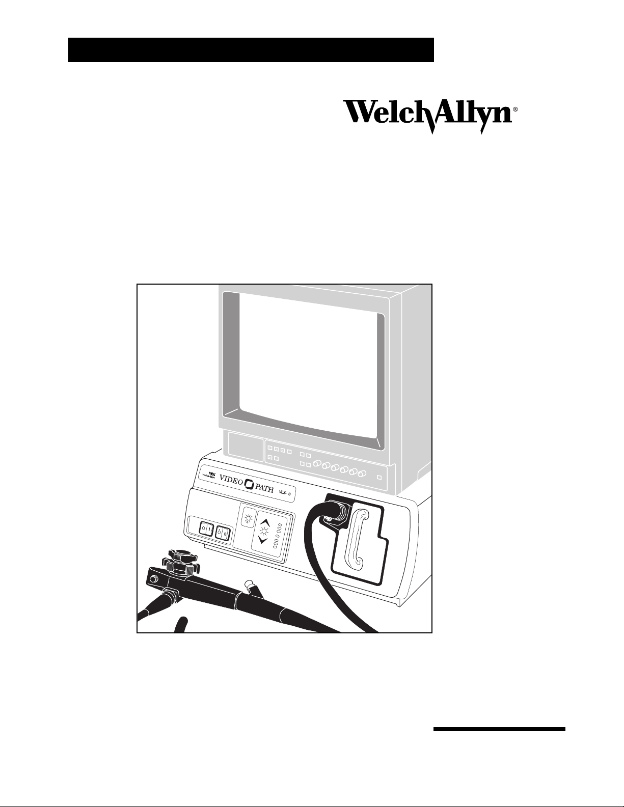
Thank you for purchasing the Welch Allyn VideoPath VLX-20 Light
Source. The operating and maintenance instructions found in this manual
should be followed to ensure many years of reliable service. Please
read these instructions thoroughly before attempting to use your new
VLX-20 Light Source. This device serves as a light and air/water source
for the Welch Allyn VideoPath System and can be used with any compatible Welch Allyn videoscope.
IMPORTANT: The material outlined in this manual should be reviewed
and understood prior to operation of the equipment.
CAUTION: Federal Law restricts this device to sale by/to or on the order
of a physician or other appropriately licensed medical professional.
WARNING: The user of this equipment should be thoroughly trained
in the medical procedures appropriate to the instrumentation.
Furthermore, time should be taken to read and understand these
instructions before performing any procedures. Instructions for
other equipment used in conjunction (e.g., suction machines, electrosurgery generators) should also be read and understood. Failure
to do so may result in injury to the patient and/or damage to the
instrument.
The CE mark on this device indicates it has been tested to and conforms
with the provisions noted within the 93/42/EEC Medical Devices Directive.
Authorized European Representative Address:
European Regulatory Manager
Welch Allyn, Ltd.
Kells Road, Navan,
County Meath,
Republic of Ireland
Tel.: 353-46-79060
Fax: 353-46-27128
Page 3

Table of Contents
Conventions
General Precautions..........................................................................................2
Symbols.............................................................................................................3
Specifications
....................................................................................................4
Components
.......................................................................................................5
VLX-20 Light Source .........................................................................................5
Optional Accessories.........................................................................................5
Nomenclature
Light Source Front Panel...................................................................................6
Light Source Bottom View.................................................................................7
Water Bottle/Cleaning Bottle .............................................................................7
Light Source Back View.....................................................................................8
Monitor..........................................................................................................9-10
Connection Diagrams
....................................................................................11
Preparation For Use
General Precautions........................................................................................12
Setting Up the VLX-20 Light Source...............................................................13
Connecting the VideoEndoscope and Water Bottle...................................13-14
Inspection
Powering Up the Light Source.........................................................................14
Lamp Ignition...................................................................................................15
Inspection of Illumination ............................................................................15-16
Inspection of Endoscope Control Buttons.......................................................16
Inspection of Air/Water Feed...........................................................................16
Operation
Power Switch...................................................................................................17
Lamp Ignition...................................................................................................17
Illumination Brightness ....................................................................................17
Air Pump .........................................................................................................17
Video Printer....................................................................................................18
Electrosurgery..................................................................................................18
Maintenance and Storage
After Each Procedure......................................................................................19
Water Bottle Cleaning......................................................................................19
Enzymatic Solutions....................................................................................19
Water Bottle Sterilization.................................................................................20
ETO Sterilization..............................................................................................20
Cold Sterilization..............................................................................................21
Sterilizing/Disinfecting Solutions......................................................................21
Bottle Storage..................................................................................................21
Replacing Lamps........................................................................................22-23
Light Source Storage .......................................................................................24
Troubleshooting
.........................................................................................25-26
VLX-20 Light Source 1
Page 4
2 VideoPath
Conventions
WARNING:Alerts the user to possible serious injury, death or other
adverse reaction associated with the use or misuse of the device.
CAUTION: Indicates a potentially hazardous situation which, if not
avoided, may result in minor or moderate injury. It also alerts against
unsafe practices.
NOTE:
Provides supplemental information to the text and indicates
a potentially hazardous situation, which, if not avoided, may
result in property damage. Additionally it highlights important
information on the use of this equipment.
General Precautions
• For safety, this light source should only be coupled to a grounded 100-240V AC outlet.
• The light source should not be operated in the presence of flammable or explosive
gases or chemicals or installed in areas where these materials are commonly utilized.
• To avoid overheating, the light source should be positioned on a hard, level surface and
the back of the light source should not be positioned closer than 6" to any wall.
• Keep all liquids away from electrical equipment to avoid the possibility of operator shock
and instrument damage.
• Occasionally inspect the power cord for signs of cuts, abrasions or dents.
• The light source should never be stored or operated in areas where it could get wet or
exposed to any environmental conditions such as extreme temperature, humidity, direct
sunlight, dust, etc.
• All service to the light source must be performed by Welch Allyn or an authorized
repair center.
• Light source use should adhere to the operating conditions found in this manual.
Otherwise, instrument damage may occur and/or operator/patient safety compromised.
• High frequency surgical equipment used with the endoscope must comply with the IEC
601-2-2, Particular Requirements for the Safety of High Frequency Surgical Equipment.
NOTE:
This device complies with current required standards for electromagnetic interference and should not present problems to other equipment or be affected by other devices. As a precaution, avoid using this
device in close proximity to other equipment.
Page 5
VLX-20 Light Source 3
Conventions
(Continued)
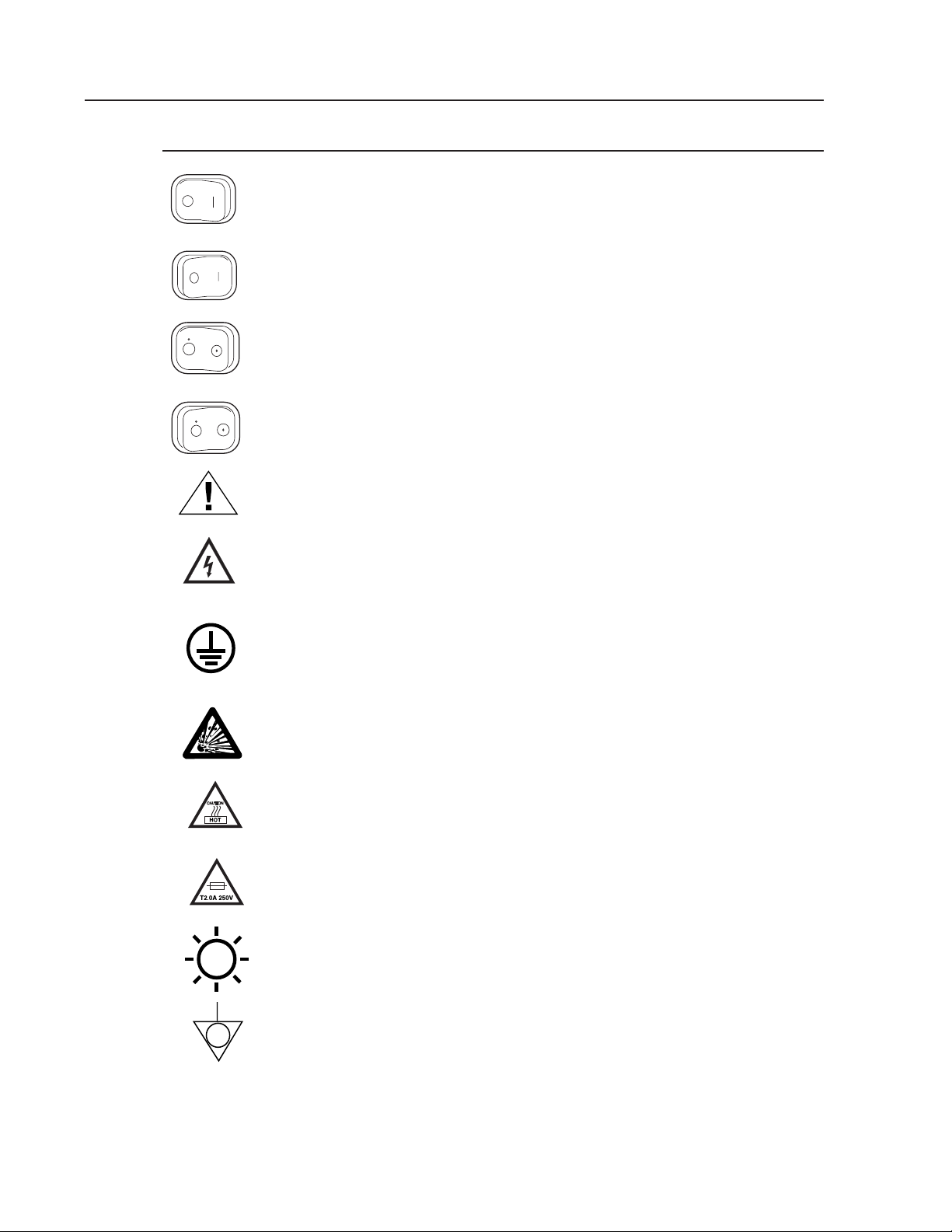
Symbols
Off: (Power: disconnects from the mains)
On: (Power: connects to the mains)
Off: (Power for air switch)
On: (Power for air switch)
Attention: Consult user’s manual for additional information
Dangerous voltage: Electric shock hazard due to high internal voltage.
There are no user serviceable parts inside the light source.
Protective earth (ground)
Risk of Explosion: Possible risk of explosion hazard if used in presence
of flammable anesthetics.
Caution High Temperatures
Warning: Risk of fire, replace fuses as marked
Caution: High Intensity Light
Equipotentiality
POWER
POWER
AIR
AIR
Page 6

4 VideoPath
Specifications
Item Specification Technical Data
Power Requirements Voltage 100-240VAC
Frequency 50/60Hz
Current 2.0 Amps Max.
Operating Mode Continuous
Dimensions H x W x D 7 x 17 x16-1/2
(18 x 43 x 42cm)
Weight 15.0 lbs. (6.8 kg)
Operating Environment Ambient Temperature +10° C (50° F) to
+40°C (104° F)
Relative Humidity 30-75%
Atmospheric Pressure 700 hPa to 1060 hPa
Transport/Storage Ambient Temperature -20° C to +49° C
Relative Humidity 95% Max.
Atmospheric Pressure 700hPa to 1060 hPa
Illumination Lamp Type Metal Halide Arc
Lamp Life (average) 750 hrs @ 1 hr per start
Brightness Adjustment Automatic Shutter
Cooling Method Forced Air
Air Feeding Pump Type Linear Motor, Free Piston
Capacity 6.5 PSIG Maximum
Flow Rate .177 c.f.m. @ 2.84 PSIG
Control Power switch activated
Water Feed System Water Compression Pressurized by pumped air
Watter Bottle Capacity 260 ml
Compatible Endoscopes Welch Allyn Color CCD only
VideoEndoscopes
Other Manufacturer’s All models with use
Fiberscopes of light source adapter
module
Color System Color mosaic CCD
Video Outputs Dual Composite (NTSC)
Dual S-Video
Output Devices VCR
Monitor
Thermal or Video Printer
Compliance Designed in Accordance UL 2601-1, IEC 60601-2-18,
IEC 60601-1, CSA C22.2
No. 601.1, CE
Degree of explosion proofing Use in potentially flammable
surroundings prohibited
Classification Electro medical equipment Class I Equipment
Degree of protection against Use on heart is prohibited
electrical shock
Fuse T2.0A-250V
Lamp Welch Allyn Part No. 04060 Lamp Voltage 60 Volts
Page 7
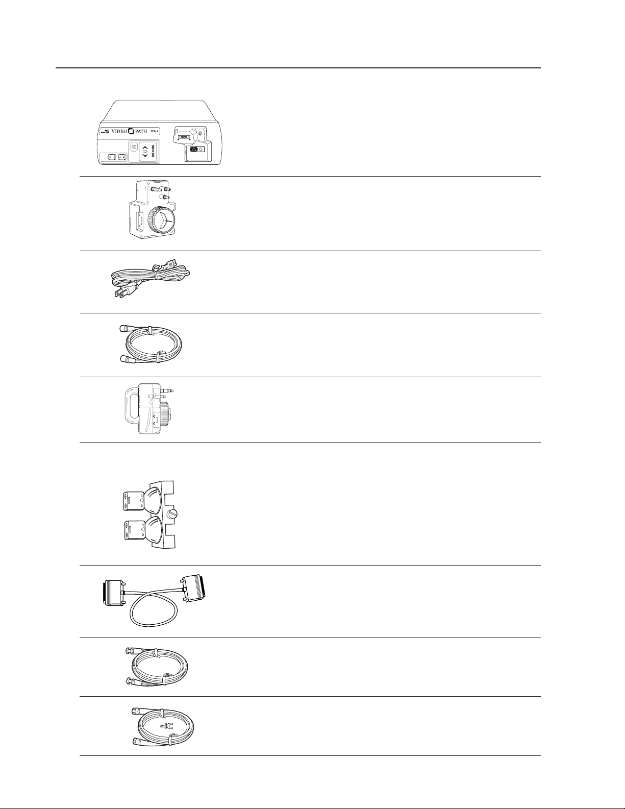
Components
VLX-20 Light Source Includes:
45500 Light Source
45510 Water Bottle
761076-0 Power Cord
45512 S-Video Cable
45520 Cleaning/Disinfection Bottle
Optional Accessories
04060 Lamp Replacement Assembly
65158 RS-232 Communication Cable
45513 NTSC Composite Video Cable
33915 Electrosurgical Ground Kit
VLX-20 Light Source 5
POWER AIR
!
STANDBY
PICTURE
BRIGHTNESS
LAMP
SERVICE
LAMP
IGNITION
2
Page 8
6 VideoPath
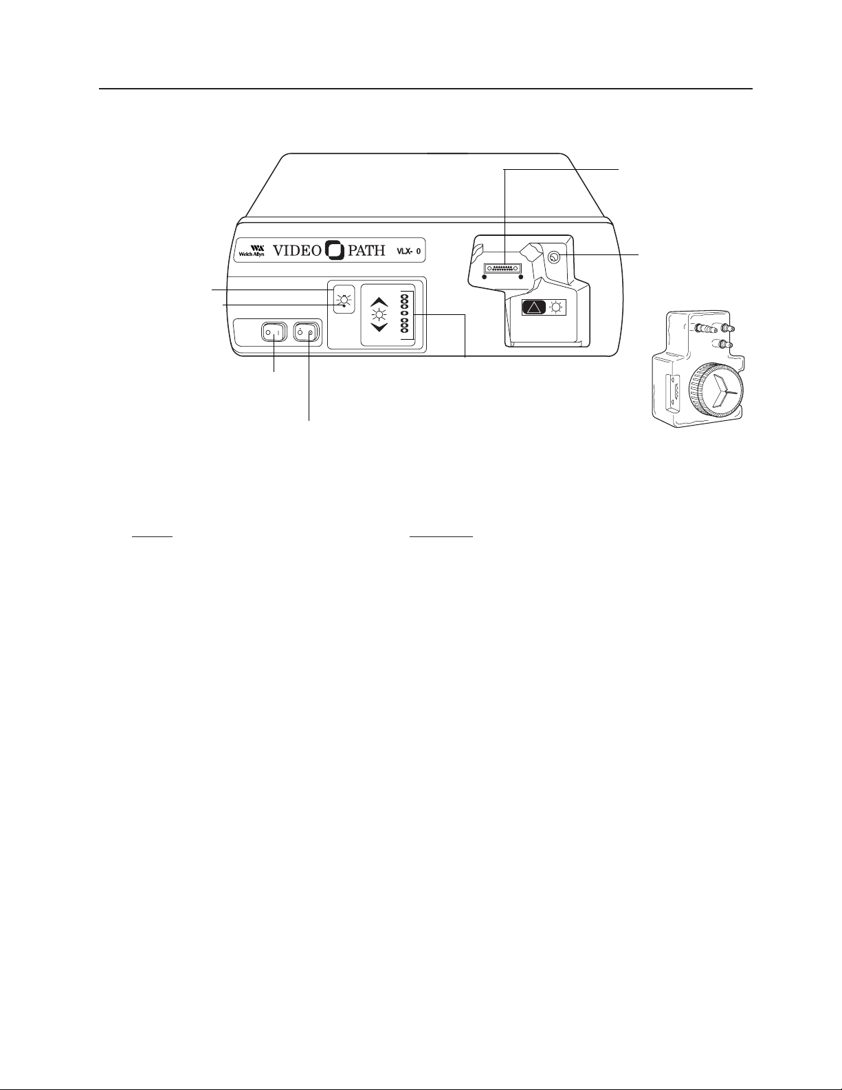
Nomenclature
Light Source Front Panel
Front Panel
Name
Function
1. Main Power Switch Primary power control for the light source.
If not activated, other controls will not function.
2. Air Pump Switch Activates flow of air at air output port in
endoscope connector port.
3. Lamp Ignition Ignites and activates the lamps.
4. Lamp Standby Indicator When LED blinks, lamps cannot be ignited.
When LED remains on, lamps have warmed
up/cooled down and can be ignited.
5. Picture Brightness Control Pressing up or down arrows adjusts image on
monitor to desired brightness level (level indicated
by illuminated green LED)
6. Endoscope Connector Port Accepts endoscope connector terminal to transmit
light and electrical signals through the endoscope.
7. Water Bottle Water bottle couples to endoscope connector
terminal’s air and water input ports and light source
air output port.
8. Air Output Port Couples to and pressurizes the water bottle which
provides air and water to the endoscope.
POWER AIR
!
STANDBY
LAMP
IGNITION
LAMP
SERVICE
PICTURE
BRIGHTNESS
2
1. Main
Power Switch
2. Air Pump Switch
3. Lamp Ignition
4. Lamp Standby
Indicator
7. Water Bottle
5. Picture Brightness
Control
8. Air Output Port
6. Endoscope
Connector Port
Page 9
VLX-20 Light Source 7
Nomenclature
(Continued)
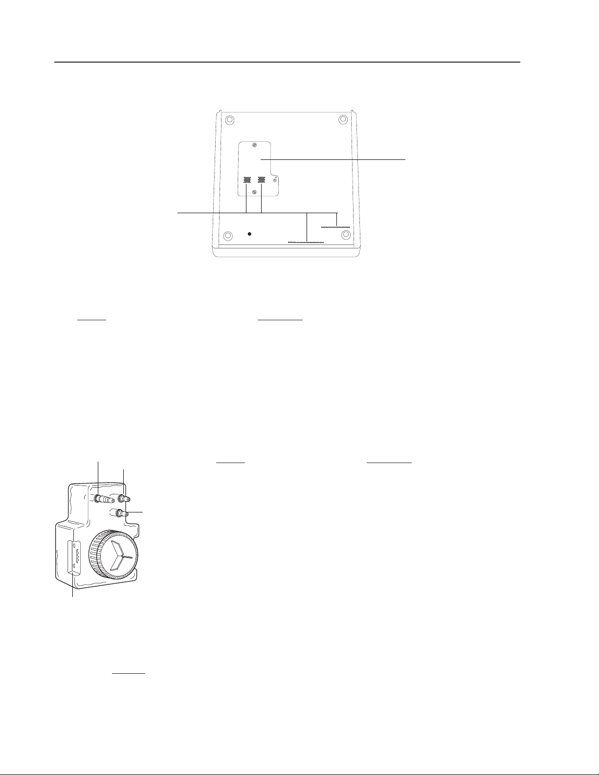
Light Source Bottom View
Light Source Bottom View
Name Function
9. Lamp Access Door Opens for lamp replacement.
(Note: If door is not properly closed, interlock power
switch will deactivate and the unit will not power up.)
10. Ventilation Holes Allows air to enter unit to cool internal components.
Water Bottle/Cleaning Bottle
Name Function
11. Air Input Connector Couples to light source
air output port.
12. Air Output Connector Couples to endoscope
air input port.
13. Water Output Connector Couples to endoscope
water input port.
14. Fill Line Indicates maximum water level
to which bottle should be
filled for normal use.
Water Bottle
NOTE:
Cleaning bottle is identical to water bottle with the exception that
it allows fluid to be introduced into the air input port of the endoscope. The bottle can be easily identified via the red CAUTION
label on the front of the bottle.
14.Fill Line
11. Air Input
Connector
12.Air Output
Connector
13.Water
Output
Connector
9. Lamp
Access Door
10.Ventilation Holes
Page 10

8 VideoPath
Nomenclature
(Continued)
Light Source Back View
Light Source Back View
Name Function
15. Power Supply Cord Couples with power cord which should be plugged
Receptacle into a 100-240 VAC outlet.
16. S-video Outputs Outputs S-video or Y/C, 4 position Mini-DIN.
17. Composite Video Outputs Outputs NTSC (composite video), BNC connector.
18. Fans Pulls room air into the light source for forced
air cooling.
19. Fuse Drawer Opens for replacement of main fuse.
20. Earth Ground Terminal Provides a terminal which is connected to
Connector earth ground through the VLX-20 line cord
(1/4-36 UNS-2A thread).
21. Equipotentiality Terminal Accepts ground connector from electrosurgery
Connector equipment to provide a secondary or redundant
ground path.
22. RS-232 Communication Communication port for use with video printers.
Connector Port
23. Aux(illiary) Port No function. Future capability.
18.Fans
22.RS-232 Communication Connector Port
19.Fuse Drawer
16.S-video Output
23.Auxilliary Port
17.Composite
Video Output
15.Power Supply Cord Receptacle
20.Earth
Ground Terminal
Connector
21.Equipotentiality
Terminal Connector
Page 11

VLX-20 Light Source 9
Nomenclature
(Continued)
Monitor
NOTE: The following is a brief overview of the nomenclature of the
SONY PVM-1350 Video Monitor. For detailed instructions,
please refer to the Operation Manual that is provided by
the manufacturer.
PLEASE REFERENCE YOUR SONY MONITOR MANUAL ENCLOSED FOR FURTHER INFORMATION.
Name Function
24. Power Depress to turn the monitor on. The indicator will light up in green.
25. Volume No function.
26. Contrast Turn clockwise to increase contrast and counterclockwise to
decrease.
27. Phase (Tint) Turn clockwise to make the skin tones green and
counterclockwise to make them purple.
28. Chroma Turn clockwise to make the color intensity higher and
counterclockwise to make it lower.
29. Bright (Brightness) Turn clockwise for more brightness and counterclockwise for less.
30. Aperture (Sharpness)Turn clockwise for more sharpness and counterclockwise for less.
31. Degauss button Press this button momentarily. The screen will be
demagnetized. Wait for 10 minutes or more before
activating this button again.
32. Input select buttons Press (light on) to select the program to be monitored.
A: For signal fed through the LINE Aconnectors.
B: For signal fed through the LINE B connectors.
C: For signal fed through the LINE C connectors.
RGB: For signal fed through the RGB connectors.
Front Panel of Monitor
24.Power
25.Volume
28.Chroma
26.Contrast
29.Bright
30.Aperture
31.Degauss
27.Phase
32.Input select
buttons
Page 12

10 VideoPath
Nomenclature
(Continued)
Name Function
33. Power Supply Cord Couples with power cord, which should be plugged
Receptacle into a 100-240 VAC outlet.
34. Line A, Line B connectors Two groups (A and B) of line input connectors for
composite video.
35. Line C connector Y/C IN (S-Video) High resolution S-Video input.
Back Panel of Monitor
33.Power Supply
Cord Receptacle
34.Line A, Line B
connectors
35.Line C connector
Page 13

Connection Diagrams
Connecting the VLX-20 with Monitor
The diagram below illustrates an example of recommended coupling between the VLX-20
and a monitor.
Connection to monitor diagram
Connecting the VLX-20 with VCR/Video Printer
The diagram below illustrates an example of recommended coupling between the VLX-20
and peripheral equipment.
Connection of the VLX-20 with VCR/Video Printer
WARNING:All video monitors and peripheral equipment used with this
system must be IEC 60601-1 or UL 2601-1 listed to comply with medical
electrical safety guidelines. If not IEC 60601-1, UL 2601-1 listed, the
monitor/peripheral equipment should be positioned outside of the 6 foot
patient contact area. Please contact Welch Allyn for more information.
NOTE:
The RS-232 cable is required for the Function Control Buttons to
perform properly.
VLX-20 Light Source 11
S-Video Out
Monitor
Monitor
VLX-20
Line C Y/C In
S-Video In
S-Video In
S-Video
Out
S-Video Out
VLX-20
Page 14

12 VideoPath
Preparation For Use
General Precautions
•Make sure the cabinet of this unit is always grounded and secure during use.
Do not disable line cord ground connection. Grounding reliability is achieved only when
light source is connected to “hospital-use” or “hospital-grade” receptacle. Inspect the
electrical plug and cord routinely. Do not use if damage is discovered.
•Do not use the light source in the presence of any flammable anesthetics.
•Do not open the light source cabinet. There is an electrical shock hazard due to the
high internal voltage.There are no user serviceable parts inside the light source.
NOTE:
Opening of the light source cabinet by a non-authorized repair
facility will void the product warranty.
WARNING: Total system risk current should not exceed 50uA. An isolation transformer is required if the total system risk current exceeds 50uA
when accessories are interconnected.
CAUTION: The light source is cooled via two vent fans located in the
back of the unit. These fans draw air from beneath the light source
through the inside and out the back and through the endoscope connector port. Verify the rear of the unit is no less than 6" from a wall and that
the source is placed on a hard surface.
• When possible, keep the light source out of patient field. Always
remove the light source from patient field while connecting or disconnecting endoscope or proximal camera system.
CAUTION: To ensure patient safety, make sure monitor is outside patient
vicinity (6 feet) during use.
CAUTION: High frequency surgical equipment used with the endoscope
must comply with the IEC 60601-2-2, Particular Requirements for the
Safety of High Frequency Surgical Equipment.
CAUTION: The chassis of the high frequency surgical equipment, if
accessible, should be connected to the Equipotentiality Terminal of the
VLX-20 Light Source to eliminate the potential of RF voltage potential
between the two devices during electrosurgery.
CAUTION: Before use, inspect the insulation of all endoscopic accessories designed for high frequency electrosurgery by consulting the
manufacturer instructions for these devices.
NOTE:
The Welch Allyn Endoscopes are Type BF and do not require
electrical connection between the endoscopes and the neutral electrode
of the high frequency generator during electrosurgery.
WARNING: If during a procedure, loss of function of the light source
occurs, terminate the procedure. Return all deflection controls of the
endoscope to the neutral position and disengage all control brakes.
Slowly withdraw the endoscope from the patient. DO NOT operate the
controls during withdrawal.
Page 15
Preparation For Use
Setting Up the VLX-20 Light Source
1. Place the VLX-20 light source onto a hard, stable surface (shelf, counter, cart, etc.)
and connect the power cord to the power supply cord receptacle located on the rear
panel of the unit. After making sure the main power switch is off, couple the remaining
end of the power cord into a properly grounded AC outlet.
NOTE:
The VLX-20 should not be placed in areas where:
• it will be exposed to fluids.
• it will be exposed to flammable gases.
• the vent fans in the rear panel will be blocked.
• the vent holes on the bottom of the unit will be blocked.
WARNING: DO NOT use a converter adapter that will convert the three
prong plug to a two prong. In this case the light source is not properly
grounded and electric shock may result.
NOTE:
Place the light source in a horizontal position for operation.
NOTE:
If the light source is placed on a mobile cart verify that the cart
is stable enough to support the unit.
Connecting the VideoEndoscope and Water Bottle
WARNING: It is essential that the instruction manuals for the Welch Allyn
VideoEndoscopes be reviewed in detail prior to using the system.
1. Fill the water bottle with clean water to the fill line indicated on the side of the bottle. Remember to:
• Change the water daily.
• Use distilled or sterile water to prevent mineral and
organic deposits in the water lines.
• If water leaks from the bottle into the light source, a
drain in the base of the endoscope connector port will
direct the water to the table top where it can be wiped up.
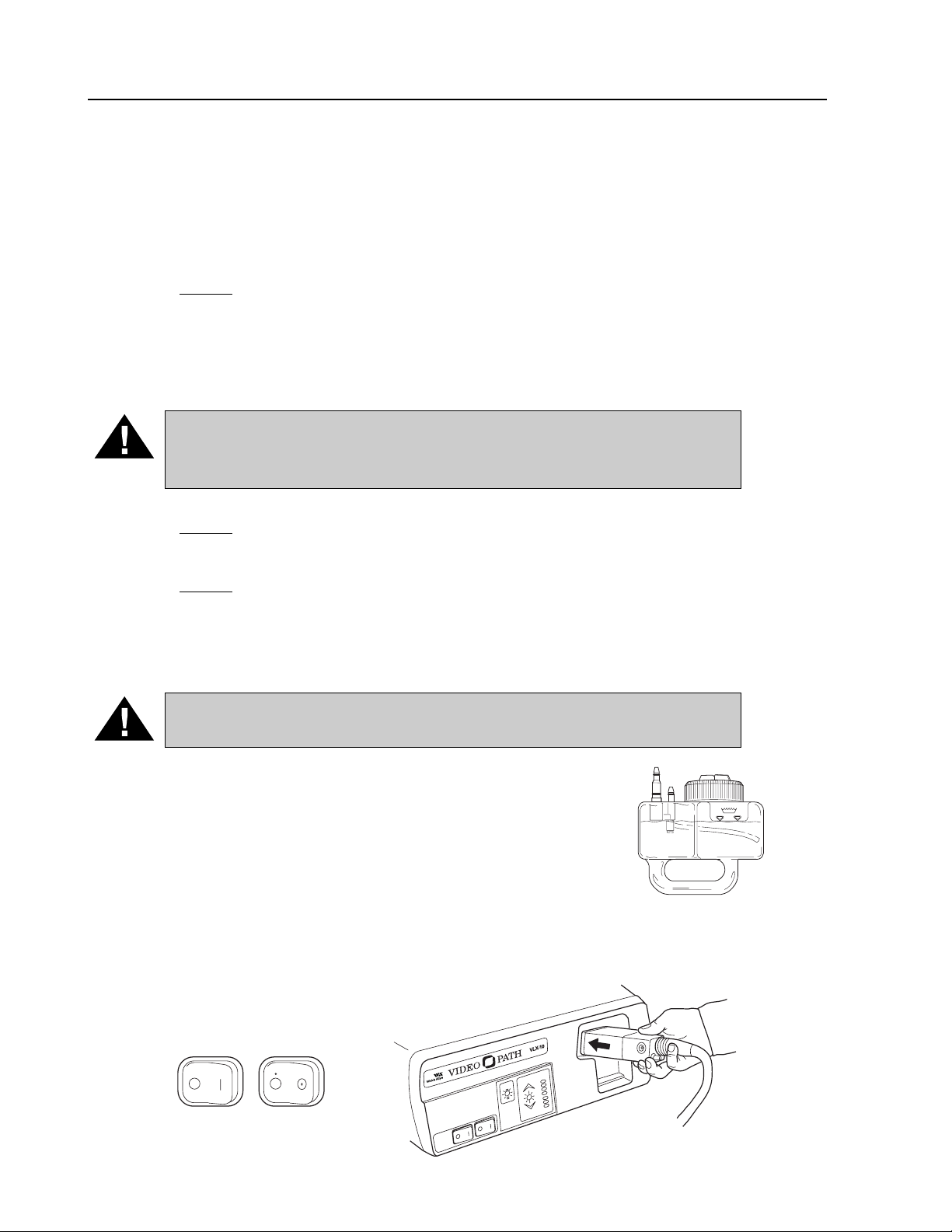
2. Verify that the light source’s main power switch is off. Plug the endoscope
connector terminal into the light source’s endoscope connector port. Advance
until the instrument clicks into place.
VLX-20 Light Source 13
POWER
OFF
LAMP
IGNITION
LAMP
SERVICE
PICTURE
BRIGHTNESS
Page 16

14 VideoPath
Preparation For Use
(Continued)
3. Insert the water bottle into the recessed area (endoscope connector port) on the front
panel of the light source. The bottle’s air and water connectors should couple to the air
output port of the light source and air and water input ports on the endoscope connector
terminal. Push water bottle until the front of the bottle is flush with the front panel of the
light box.
Inspection
Prior to every examination, the equipment should be pre-tested following the procedures
outlined in the following sections. If an abnormality is detected or suspected, do not
continue with the examination. Contact Welch Allyn Customer Service for assistance
at 1-800-535-6663.
Powering Up the Light Source
1. With the instrument coupled to the light source, activate the power switch on the light
source’s front panel. The internal cooling fans will power up and should be heard running.
The green LED Lamp Ignition/Standby light will blink for approximately 11 seconds to allow
the lamps to warm up (or if the light source has been on for an extended period of time, to
allow the lamps to cool down).
NOTE:
If the light source does not appear to power up, make sure that
the power cord is correctly connected, the lamp door cover on the
bottom of the unit is securely closed and the endoscope connector terminal is correctly engaged in the endoscope connector port.
If the unit still does not power up, contact Welch Allyn Customer
Service at 1-800-535-6663.
POWER AIR
STANDBY
PICTURE
BRIGHTNESS
LAMP
IGNITION
LAMP
SERVICE
2
Power Switch ON
Lamp Ignition
Standby Light
BLINKING
PICTURE
BRIGHTNESS
LAMP
IGNITION
STANDBY
LAMP
SERVICE
VLX-20
Page 17

Inspection
Lamp Ignition
1. When the sigmoidoscope is connected to the light source and the main power
switch is activated, the green Ignition/Standby light will blink for approximately
11 seconds. Once the green LED stops blinking, the lamps are ready to ignite.
2. Once the green Lamp Ignition/Standby light remains lit, press the Lamp Ignition
Switch. The lamps will ignite and the Lamp Ignition/Standby light will go out.
The lamps require 11 seconds to warm up. This length of time will be indicated by the center LED of the Picture Brightness Indicator which blinks until the
lamps reach full intensity. Once the Picture Brightness Indicator remains constant, the lamps are fully warmed up, and the system is ready for use.
NOTE:
If the light source is powered up without the endoscope plugged
in, the center LED in the Brightness Indicator Panel will not illuminate,
and the lamps will not ignite. The Standby light will continually blink.
WARNING: If the endoscope is removed from the light source, the
lamps will remain lit. DO NOT look directly into the lights. The intensity
of the illumination may damage your eyes. If the instrument is removed
from the light source, either turn off the main power switch or press the
Lamp Ignition/Standby switch to turn off the lamps and put them in a
standby mode.
NOTE:
If the internal cooling fans are running and the lamp ignition switch
is activated but no light is emitted from the distal tip of the endo-
scope, the lamps are not functioning. Refer to the Troubleshooting
and/or Lamp Replacement sections in this manual.
Inspection of Illumination
1. Once you have verified that the endoscope is connected
to the light source and the lamps are lit, check that a live
image appears on the monitor.
2. Make sure the endoscope’s automatic iris is working
properly. While watching the monitor, place the distal tip
of the endoscope within 1 cm of the palm of your hand
and then move it about 10 cm away from your palm. The
image brightness on the monitor at both distances should
be similar. Point the distal tip toward dim room lights. The
light being emitted at the distal end should lower significantly
depending on the ambient light levels in the room. Point the
distal tip at your palm again to verify that light is being
emitted from the endoscope.
3. Press the Brightness Control switch (the up and down arrows). The
LED light goes up/down one step with increased/decreased illumination light output.
Continually depressing the switch causes the LED light to go up/down sequentially with
increasing/decreasing light output until the maximum/minimum output is reached.
VLX-20 Light Source 15
Standby Light
Center
LED
PICTURE
BRIGHTNESS
IGNITION
STANDBY
SERVICE
LAMP
LAMP
1 cm
PICTURE
BRIGHTNESS
Page 18

Inspection
(Continued)
• Once the maximum/minimum output is reached, pressing the switch does not cause any
change.
• Do not press the Brightness Control switch with a pointed or hard object. Damage could
occur to the membrane covering.
Inspection of Endoscope Control Buttons
1. Check that the endoscope control buttons (F, C and V), positioned on the control body of
the endoscope, each beep when pressed. Refer to the Video Printer section for use of
these control buttons.
Inspection of Air/Water Feed
1. Turn on the air pump. Once activated, the sound of the air pump should be evident.
2. Test the Air and Water flow through the endoscope. First, cover the air venting hole
on top of the Air/Water valve. This should deliver air at the distal end of the endoscope
through the air nozzle. Submerge the distal end in water. Air flow will be demonstrated
by a flow of bubbles.
Testing the Air Flow
3. Remove the distal tip from the water and depress the Air/Water valve completely.
Water should flow through the water nozzle at the distal tip of the endoscope.
NOTE:
Allow 5 seconds for the water lines within the instrument
to fill.
NOTE:
Before each use, the outer surface of the portions of the endoscope and any endoscopically-used accessories which are intended
to be inserted into a patient should be checked to ensure there are no
unintended rough surfaces, sharp edges or protrusions which may
cause a safety hazard.
16 VideoPath
Biopsy Seal
Cover
Depress
Water Nozzle
Page 19

VLX-20 Light Source 17
Operation
Power Switch
With the endoscope connected to the light source, activate the power switch on the light
source front panel. The green LED Lamp Ignition/Standby light will blink for approximately
11 seconds to allow the lamps to warm up (or if the light source has been on for an extended
period of time, to allow the lamps to cool down).
Lamp Ignition
Once the green Lamp Ignition/Standby light remains lit, press the Lamp Ignition switch.
The lamps will ignite and the Lamp Ignition/Standby light will go out. The lamps require 11
seconds to warm up. This length of time will be indicated by the center LED of
the Picture Brightness Indicator, which blinks until the lamps reach full intensity.
Once the Picture Brightness Indicator LED remains constant, the lamps are fully
warmed up, and the system is ready for use.
NOTE:
Allow the system a full 15-20 seconds to warm up before
beginning a procedure or image color will be adversely affected.
NOTE:
If the light source is powered up without the endoscope plugged
in, the Standby light will continually blink, and the lamps cannot
be ignited.
Image Brightness
Picture Brightness: The average brightness of the image on the monitor can be manually
adjusted. Press the Picture Brightness Control switch (the up and down arrows). The LED
light goes up/down one step with increased/decreased Picture Brightness (viewed on the
monitor). Continually depressing the button causes the LED light to go up/down sequentially
with increasing/decreasing Picture Brightness until the maximum/minimum output is reached.
Air Pump
Turn on the Air switch.
POWER AIR
ON
AIR
ON
POWER AIR
STANDBY
PICTURE
BRIGHTNESS
LAMP
IGNITION
LAMP
SERVICE
POWER AIR
STANDBY
PICTURE
BRIGHTNESS
LAMP
IGNITION
LAMP
SERVICE
Standby light will
continually blink
Blinking
Center
LED
PICTURE
BRIGHTNESS
Page 20

Operation
(Continued)
Video Printer
The VS-200 VideoEndoscope, when used with the VLX-20 Light Source and compatible
video printer, has the ability to capture, store and print endoscopic images. The function controls on the endoscope interface with the system for convenient control of the Freeze, Copy
and Video features. The RS-232 Cable must be connected from the VLX-20 Light Source to
the video printer for this feature to perform properly. Please refer to the Connection Diagrams
section of this manual for further information. It is important that the user review and understand the instruction manuals associated with all the components of the system, including the
VideoSigmoidoscope and video printer.
To save and print an image, perform the following:
F (Freeze) Button – Push to freeze an image.
C (Copy) Button – Push to activate the print function.
V (Video) Button – Push to return to the live image after completion of the print process.
Returning to the live image prior to printing a frozen image will result in the loss of the
frozen image. Please refer to the instruction manual of the video printer for more
detailed instructions.
Electrosurgery
The user must carefully read and understand all the instructions in the operating manuals
supplied with the electrosurgical generator and associated accessories. All electrosurgical
equipment must be thoroughly inspected prior to use. Only the user can determine if the
condition of the electrosurgical generator and accessories is correct and safe for clinical use.
1. The electrosurgical accessories should be introduced through the VS-200
VideoSigmoidoscope in the same manner as described in the Biopsy Forceps section
of the VS-200 Instruction Manual. Consult the VS-200 manual for further detail.
2. The active portion of the electrosurgical accessory should always be clearly visualized
before applying electrical energy to the instrument.
CAUTION: High frequency surgical equipment used with the endoscope
must comply with the IEC 601-2-2, Particular Requirements for the Safety
of High Frequency Surgical Equipment.
CAUTION: The chassis of the high frequency surgical equipment, if
accessible, should be connected to the Equipotentiality Terminal of the
VLX-20 Light Source to eliminate the potential of RF voltage potential
between the two devices during electrosurgery.
CAUTION: Before use, inspect the insulation of all endoscopic accessories designed for high frequency electrosurgery.
CAUTION: Avoid using high frequency surgical equipment where
explosive gas concentrations may be in the area of use.
NOTE
: The maximum rated recurring peak voltage of the high frequency
generator used with this endoscope for electrosurgery shall not
exceed these limits.
Cut Mode 1000 Volts peak
Coagulation Burst Mode 2000 Volts peak
Coagulation Spray Mode 3000 Volts peak
18 VideoPath
Page 21

VLX-20 Light Source 19
Maintenance and Storage
Light Source–After Each Procedure
NOTE: Some peripheral devices may have to be turned off before
powering down the VLX-20 light source to avoid compromising
their operation. Refer to the instructional manuals that accompanied each of the components to determine the proper order
in which to turn off the components.
Disconnect the water bottle and endoscope.
Wipe all of the surfaces of the light source with a gauze dampened slightly with alcohol.
NOTE:
Never allow liquids to be splashed onto the VLX-20. Do
not allow the connector interfaces and ventilation ports to
become wet.
Water/Cleaning Bottle–Cleaning
WARNING: As with all endoscopic accessories, the water bottle must
be cleaned thoroughly. Failure to do so could result in incomplete or
ineffective sterilization.
1. After use, the entire bottle assembly (bottle and cap) should be washed with enzymatic
solution and dampened gauze or scrub brush. Use an enzymatic detergent for soiled
items.
Enzymatic Solutions
The materials listed below are safe for cleaning the water/cleaning bottles if used according to the manufacturer’s instructions for cleaning and in accordance with procedures
detailed in the cleaning section of this manual.
Brand Name Source Usage
Endozime The Ruhof Corp. Follow
Klenzyme Calgon Vestal Labs Manufacturer’s
Enzy-Clean Burnishine Products Instructions
Metrizyme Metrex Research Corp.
Enzol J & J Medical
2. To access difficult to reach areas, use ultrasonic cleaning. Use an operating frequency
of 40 kHz or higher for a period of 5-10 minutes.
3. After washing the bottle with enzymatic solution, rinse and dry thoroughly all of the surfaces of the bottle. Use a gauze or clean, lint-free cloth to dry the surfaces. You may also
use compressed air and 70% alcohol to facilitate drying of hard to reach areas.
Page 22

20 VideoPath
Maintenance and Storage
(Continued)
Water/Cleaning Bottle Sterilization
Make sure the bottle has been thoroughly cleaned prior to ETO sterilization.
NOTE:
DO NOT steam sterilize (autoclave) this bottle.
ETO Sterilization
1. Make sure to follow the parameters listed below for ETO sterilization.
Temperature MUST NOT exceed 55° C (131° F)
Pressure MUST NOT exceed 1.7 kg/cm2 (24PSI)
Humidity MUST NOT exceed 70%
Time MUST NOT exceed 4 hours
2. Following ETO sterilization, aeration time of 72 hours is required. You may use
an aeration chamber to shorten the time to 12 hours, but the temperature must be
between 49° C (120° F) and 55° C (131° F).
Page 23

VLX-20 Light Source 21
Maintenance and Storage
(Continued)
Cold Sterilization
1. After thoroughly cleaning and drying, the water bottle may be soaked in the sterilant
for the time period recommended by the manufacturer and accepted by the user as
appropriate.
Sterilizing/Disinfecting Solutions
The materials listed below are considered safe for sterilization/disinfection of the water bottle
if used according to the manufacturer’s instructions for cleaning and in accordance with procedures explained in the disinfecting section of this manual. Make sure that the sterilant
manufacturer’s instructions for contact time are followed. Each solution and brand may have
different times to achieve sterilization.
Solution Brand Name Source Usage
Cidex (14 day) (2.4%) J & J Medical
Glutaraldehyde Wavicide-01 (2.5%) Wave Energy System Inc.
Metricide (14 day) (2.6%) Metrex Research Corp.
CAUTION: Never exceed the 12 hour maximum immersion.
2. Rinse the bottle with clean water, making sure that all of the sterilant is removed
from the bottle.
NOTE:
All final rinses should be made with sterile water.
3. Dry the water bottle. Compressed air and 70% alcohol can be used to facilitate drying.
Bottle Storage
Make sure that all water is removed from inside the water bottle assembly prior to storage
to reduce the potential for bacteria colonization. Compressed air and 70% alcohol should
be used to facilitate drying.
NOTE:
Refer to the manual that accompanied your endoscope for
cleaning and sterilization procedures.
Follow
Manufacturer’s
Instructions
Page 24

22 VideoPath
Maintenance and Storage
(Continued)
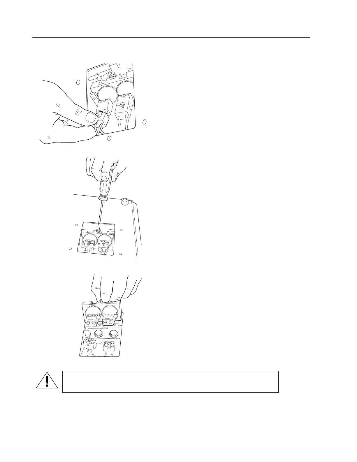
Replacing Lamps
WARNING: Before removing the lamps, allow 5 minutes for the lamps to
cool with the internal fans running and lamps off.
If the lamps need to be replaced, follow the steps below using a Welch Allyn lamp
(Part #04060).
NOTE:
If the lamps have been in operation prior to failing, they need to
be cooled prior to replacement. This can be achieved by depressing the lamp ignition switch. The standby light will then blink signifying that the lamps are off. Allow the internal fans to run for
5 minutes with the lamps off to cool them prior to replacement.
1. Turn off the power switch to the light source.
2. Disconnect the power cord from the wall receptacle.
3. Disconnect the power cord from the receptacle on the rear panel
of the light source.
4. Remove the water bottle and the endoscope.
5. Turn the light source over on its back on a horizontal surface.
6. Open the lamp access plate on the bottom of the light source by
inserting a coin in the slots to loosen the screws.
POWER
AIR
OFF
Loosen Screws
Page 25
VLX-20 Light Source 23
Maintenance and Storage
(Continued)
7.Disconnect the lamp electrical connections, located
on the back of each lamp, by pulling straight back
and slightly up on the plugs.
8.Loosen the lamp plate
thumb screw.
9.Lift the lamp plate out.
CAUTION: Do not touch the glass of the lamp during removal or installation. Oils from your fingers can cause the lamp to explode when ignited.
10. Install replacement lamp
(Welch Allyn Part No. 04060)
in reverse order of removal.
Page 26

Maintenance and Storage
(Continued)
Light Source Storage
• Disconnect the power cord from the receptacle.
• Wipe the external surface of the light source and the power cord with gauze moistened
with alcohol.
• Do not store the unit where it can be exposed to liquids.
• Store in a clean, dust-free environment at room temperature. Avoid direct sunlight and
areas of high temperature and humidity.
• Do not wind the power cord so tightly that it is permanently crushed, twisted or bent.
NOTE:
This equipment contains no hazardous materials and can be disposed of
after its useful life without any environmental risks.
CAUTION: Avoid crushing or puncturing any video monitor due to risk of
CRT implosion. Consult your local waste authority for safe disposal.
24 VideoPath
Page 27

VLX-20 Light Source 25
Condition Check Action
Power does not come on. Power cord Make sure proper connection
at unit and wall outlet.
Lamp housing door Make sure lamp housing door
is properly closed.
Fuse blown Remove fuse panel and replace
blown fuse with T2.0A-250V fuse.
Power socket Plug the power cord into a
socket known to work.
No image on monitor. Monitor/other peripheral Make sure power is on for all
devices devices.
Cable connections Make sure all video cables
are connected properly.
Endoscope Make sure the endoscope is
properly connected.
Lamp Make sure the lamps are
ignited.
Monitor Input Selection Make sure correct input
selection is made on the
front panel.
Lamps will not light. Lamp cartridge Make sure lamp assembly
is installed properly.
Make sure lamps are not
burned out.
No air delivery at distal Air pump Make sure the air pump is end of endoscope. turned on.
Water bottle Make sure the water bottle is
properly coupled to the light
source.
Make sure water bottle cap is
properly secured.
Check “O” rings on water
bottle for damage.
No water delivery at distal Air pump Make sure the air pump is end of endoscope. turned on.
Water bottle Make sure the water bottle is
properly coupled to the light
source.
Check “O” rings on water bottle
for damage.
Make sure the water bottle is
filled to the fill line.
Troubleshooting
Page 28

26 VideoPath
Condition Check Action
Electronic Function Controls RS-232 cable not connected Connect RS-232 cable do not operate. between VLX-20 Light
Source and video printer
Video printer not in proper Adjust video printer until
signal input mode proper input mode is
selected (Composite,
S-Video, RGB)
Printer not adjusted to Set printer to 9600 baud
proper baud rate
Troubleshooting
(Continued)
Page 29

Page 30

Welch Allyn, Inc.
4341 State Street Road
P.O. Box 220
Skaneateles Falls, NY 13153-0220
Telephone: 315-685-4560
1-800-535-6663
Printed in U.S.A. Part No. 455001 Rev. C
 Loading...