

Page 1

Multi-Operatory
Kreativ Menu
Manuals
Air Abrasion Accessory
Instructions for Use
Please read this manual thoroughly
prior to first use
Copyright Notice:
Copyright © 1999, Kreativ, Inc. All rights reserved. No part of this manual
may be reproduced without written permission from Kreativ, Inc.
Manufactured by:
Kreativ, Inc. (USA)
9025 Balboa Avenue
San Diego, CA 92123
European Regulatory Manager
Welch Allyn LTD.
Navan, Co. Meath
Republic of Ireland
Ph: 353-46-79060
Page 2

TABLE OF CONTENTS
1. INTRODUCTION AND GENERAL INFORMATION 3
NTRODUCTION
I
URPOSE OF THIS MANUAL
P
ENERAL INFORMATION AND FEATURES
G
UNCTIONAL DESCRIPTION
F
PECIFICATIONS
S
2. SAFETY 7
ARNINGS
W
AUTIONS
C
RODUCT SAFETY LABELING
P
ECYCLING INSTRUCTIONS
R
3. SYSTEM UNPACKING, SETUP, AND OPERATIONAL VERIFICATION 9
NPACKING
U
ET-UP
S
PERATIONAL VERIFICATION
O
(N
OTE
HE MULTI-OPERATORY ACCESSORY MUST ALWAYS BE POWERED FIRST
: T
.) 11
11
3
3
4
5
6
7
7
8
8
9
9
4. OPERATING INSTRUCTIONS 13
PERATION
O
13
5. PREVENTIVE MAINTENANCE AND TROUBLESHOOTING 14
REVENTIVE MAINTENANCE
P
ERIODIC MAINTENANCE
P
ROUBLESHOOTING
T
ULTI-OPERATORY PARTS/ACCESSORIES
M
USTOMER REPLACEABLE COMPONENTS
C
PTIONAL ACCESSORY KIT
O
NEUMATIC FOOTSWITCH
P
ICRODENTISTRY PRODUCTS
M
14
15
15
17
17
17
18
18
6. RETURNS, ADJUSTMENTS AND LIMITED WARRANTY 19
ETURNS AND ADJUSTMENTS
R
ULTI-OPERATORY ACCESSORY LIMITED WARRANTY
M
TORAGE AND SHIPMENT
S
19
19
20
990229 REV B2
Page 3

1. Introduction and General Information
Introduction
The Kreativ Multi-Operatory Air Abrasion Accessory is an accessory extending
the use of the Mach 5.0 and the Mach 5.0 Plus (Mach 5/5+) family of air
abrasion systems into two dental operatories separated by distances of up to 32
feet, while maintaining the remote control capabilities of the Mach 5/5+ system
in both operatories. Simultaneous operation in both operatories is not
supported.
Every attempt has been made to make this manual a comprehensive overview of
the Kreativ Multi-Operatory Accessory.
this manual thoroughly before you attempt to set up or use the equipment
It is very important that you read
Chapter
1
.
Purpose of this Manual
This manual should be thoroughly studied before installing and using the
equipment. Please call your nearest authorized Welch Allyn / Kreativ service
representative if you need additional information regarding installation,
operation, or service of the instrument.
Chapter One provides an overview of the system, and covers the use of the
manual, features of the Multi-Operatory Accessory, specifications, and other
general information.
Chapter Two is a listing of all product Warnings and Cautions. Warnings relate
to issues that could be harmful to either the user or the patient, while Cautions
cover issues that could unnecessarily damage the equipment.
attention to this chapter
Chapter Three covers the initial unpacking, set-up, and operational verification
of the unit. This section should also be referred to whenever the unit is moved
from one location to another or stored for extended periods of time.
Please pay special
.
990229 REV B3
Page 4

Chapter Four is an operational description of the Kreativ Multi-Operatory
accessory.
Chapter Five provides preventive maintenance and troubleshooting procedures.
Also included is a replacement part and accessory list for re-ordering your
supplies.
Chapter Six is the warranty policy for the Kreativ Multi-Operatory accessory.
General Information and Features
The Kreativ Multi-Operatory Accessory offers the capability of extending the
use of a Mach 5/5+ Air Abrasion system into two dental operatories without the
additional cost of a second air abrasion system, or the requirement of moving
the air abrasion unit between the two operatories. The air abrasion system can
be located up to 16 feet from either operatory.
The Multi-Operatory Accessory uses the same air controlling technology as the
Mach 5/5+ to reliably route abrasive/air to either of the selected operatories. The
unit automatically senses when a handpiece is removed from its cradle, and
activates the related footswitch. The other operatory is locked out from use or
input whenever the handpiece from the operatory in use is uncradled.
Other features of the Kreativ Multi-Operatory Accessory include:
Second Remote and footswitch is provided for the second operatory
•
Automatic blanking of idle remote display
•
Convenient access to pinch tubes for periodic maintenance
•
Direct mounting to front of Mach 5/5+ system
•
Optional rear-mounting capability
•
Ability to bypass remote when handpiece is removed for sterilization
•
Optional dental chair integration kit to eliminate multiple footswitches
•
990229 REV B4
Page 5
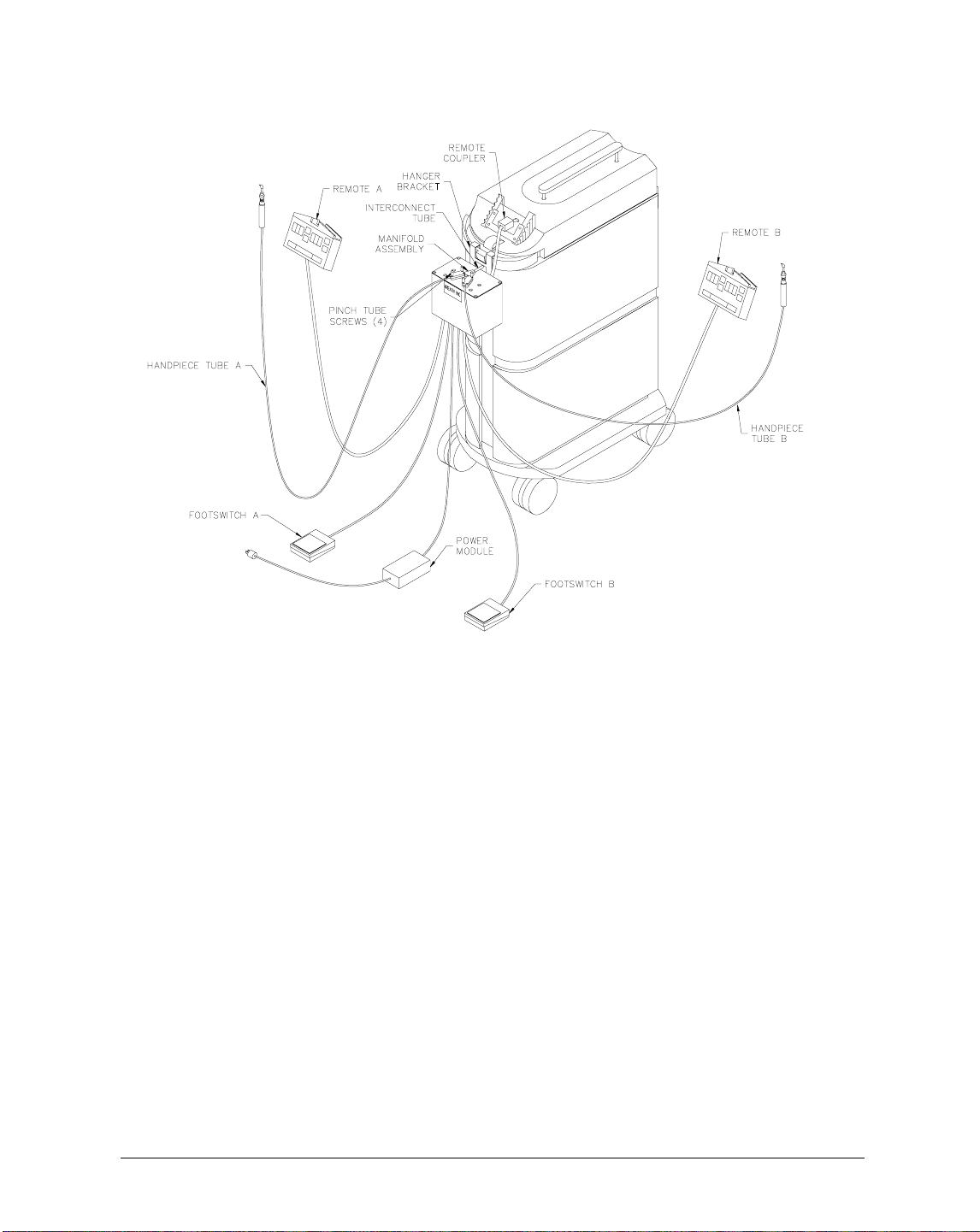
Installation Drawing (front-mount position)
Functional Description
Figure 1
Pinch Tube Screws
- Access is provided to the pinch tubes by removing the
pinch tube screws, then removing the pinch tube top block.
Hanger Bracket -
Mounts over the accessory drawer in the Mach 5/5+ to
position the Multi-Operatory unit in front of the Mach 5/5+.
Footswitch -
Connects into the bottom of the Multi-Operatory Accessory and
runs to each of the operatories to initiate air/powder flow.
Remote -
Connects to the back of the Multi-Operatory Accessory and runs to
each of the operatories to control the Mach 5/5+ when active.
Handpiece Tube -
Connected to the output end of each pinch tube, and routes
to each operatory, provides air/powder to the handpiece (handpieces provided
with the Mach 5/5+ accessory kit).
990229 REV B5
Page 6

Manifold Assy
- Provides air/abrasive to both pinch tubes when connected with
its interconnect tube.
Power Module
Interconnect Tube
manifold with the Mach 5/5+ abrasive air outlet fitting.
Remote Coupler
remote control cable.
Specifications
For further technical information, please contact your sales representative or the
Kreativ Service Center.
Power Input 100-240 V~, 50/60 Hz, 0.75-0.35 A
Weight 5.5 lbs. (2.5 kg)
Dimensions 6.3”H x 4.1”L x 6.5”W (w/o mtg. bracket)
Environmental Limitations Operating Storage/Transport
- Provides power to the Multi-Operatory unit.
- Tubing connecting the Multi-Operatory unit pinch tube
- Connects the Multi-Operatory Accessory to the Mach 5/5+
(16 x 10.4 x 16.5 cm)
Temperature +41 °F to 104 °F +14 °F to 158 °F
(+10 °C to 40 °C) (-10 °C to 70 °C)
Humidity 10 % to 90 % non-condensing
Pressure 7.3 psia to 15.4 psia
(50 kPa to 106 kPa)
Maximum tubing length +/- 16 ft from Mach 5/5+, 32 ft total
between operatories
990229 REV B6
Page 7

2. Safety
Warnings
Chapter
2
WARNING:
beyond those items described in the maintenance section. Failure to heed this
warning may result in equipment damage and/or personal injury.
WARNING:
properly grounded electrical outlet.
WARNING:
required at the recommended intervals. Failure of a pinch-tube could cause
damage to the Multi-Operatory unit, rendering it inoperable. See section under
Periodic Maintenance
Cautions
CAUTION:
of materials or accessories supplied by other manufacturers may result in
damage to the unit and will void the factory warranty.
CAUTION:
successful use of the unit in order to provide safe and efficient patient care.
CAUTION:
operative procedures.
Do not attempt to internally service the Multi-Operatory unit
Make sure that the Kreativ Multi-Operatory unit is connected to a
Periodic inspection and/or replacement of the pinch-tubes is
for recommended intervals.
Do not substitute non-Kreativ, Inc., materials or accessories. Use
Sound clinical judgment and common sense are essential to the
Always follow “standard of care” protocols in performing dental
CAUTION:
for loose or damaged parts before using it again.
If the unit is dropped, unplug and safety check it very thoroughly
990229 REV B7
Page 8

Product Safety Labeling
Type B equipment (defines the degree of protection against
electrical shock)
Refer to Operator’s Manual
Alternating Current (AC)
Recycling Instructions
Device:
All covers and housings should be recycled as steel or aluminum.
•
Plastic parts should be removed from the metal pads before recycling (e.g.,
•
power inlet, footswitch connector, main switch, etc.)
All printed circuit boards should be recycled as electronic devices.
•
Accessories:
All spare parts should be recycled according to the instructions above.
•
Products that have been in contact with the patient should be cleaned and
•
sterilized.
Packaging:
The carton, all other plastics, and inserts should be recycled (cardboard,
•
foam, polyethylene).
ALL RECYCLING MUST BE IN COMPLIANCE WITH THE RELEVANT
NATIONAL LAWS. GOVERNMENT AUTHORIZED RECYCLING
CENTERS MUST BE USED.
ENVIRONMENTALLY RELEVANT MATERIALS:
COMPONENTS LIST OF MATERIALS
Enclosure and all
Steel, Aluminum
brackets
Printed Circuit Boards Epoxy, FR4
THERE ARE NO HAZARDOUS MATERIALS PRESENT IN THIS PRODUCT.
990229 REV B8
Page 9

Chapter
3
3.
System Unpacking, Setup, and Operational Verification
Unpacking
Carefully remove the unit from the shipping container and inspect for shipping
damage. Should any sign of shipping damage be evident, please call your
nearest authorized Welch Allyn / Kreativ service representative immediately.
Keep all shipping containers in the unlikely event that the unit needs to be
returned for repair.
Set-up
1. Prior to setting up and installing the Multi-Operatory Accessory, verify your
2. Verify receipt of all appropriate accessories using the checklist enclosed
Mach 5/5+ system is operating properly.
with your Multi-Operatory Accessory.
Figure 2
990229 REV B9
Page 10

Mounting Bracket and Connector Installation
3. Install the hanger bracket onto the rear of the Multi-Operatory Accessory
using the Phillips head screws provided in the accessory kit, as shown in
Figure 2.
4. Ensure the Mach 5/5+ is turned off. Remove the Mach 5/5+ remote from its
mount if it is mounted on the air abrasion unit, and unplug the interconnecting cable.
5. Disconnect the existing footswitch from the Mach 5/5+.
6. Install the connectors for the existing Mach 5/5+ footswitch and remote onto
the Multi-Operatory Accessory, grouping the connectors on either side (but
the same side) as shown in Figure 2. Use the 20 foot cables supplied with
the Multi-Operatory Accessory for both remotes.
NOTE:
The footswitch supplied with the Mach 5/5+ must be installed in
the operatory which has the shortest run between the operatory and the Mach
5/5+ system, a total of up to 12 feet (limited by the footswitch). If a longer
footswitch cable is needed, refer to section 5 for optional parts and
accessories.
7. Install the connectors for the second operatory footswitch and remote onto
the Multi-Operatory unit, grouping the connectors on the remaining side as
shown in Figure 2.
8. Install the power cable from the power supply unit onto the power supply
connector located on the bottom of the Multi-Operatory unit.
9. Install the 1 ½ inch long interconnect tube by screwing the brass fitting into
the air manifold located on the top of the Multi-Operatory unit. Ensure this
fitting is air tight. Hand tightening should be adequate.
10. Pull the accessory tray located at the top of the Mach 5/5+ unit out several
inches, and place the hanger bracket, with the Multi-Operatory unit, over the
front of the accessory tray. Gently move the unit back with the accessory
tray, until the protruding male air fitting is aligned with the female air fitting
located on the front of the Mach 5/5+. Push the unit back until the air fitting
locks securely into the Mach 5/5+ system. If there is any difficulty, ensure
all traces of abrasive powder are removed from the Mach 5/5+ air fitting by
blowing the powder from the connector with compressed air.
11. Remove the thumbscrews (4) from the black pinch tube covers located on
the top of the unit, and remove the black covers. Install a pinch tube over
each of the fittings on the ends of the provided 20 ft long air/abrasive
990229 REV B10
Page 11

handpiece tubes. Install the resulting pinch tube/abrasive tube assembly into
each of the two connector fittings on the manifold assembly.
12. Install the pinch tubes into their respective pinch tube blocks, and replace
the black covers and thumbscrews, making sure the tube fittings are captured
properly by the pinch tube top blocks.
CAUTION: Ensure the thumbscrews are tight and the covers pulled
down completely. Failure to install these components properly could
result in air/abrasive leaks in the unused handpiece.
13. Route the air hoses with the footswitch and remote wiring going to each
operatory from either side of the Multi-Operatory unit. The cabling can be
bundled together and tied with the cable ties provided in the accessory kit.
14. Route the footswitch cable extending from the bottom of the MultiOperatory unit under the Mach 5/5+, and connect to the footswitch
connector input of the Mach 5/5+.
15. Route the remote RJ45 cable extending from the bottom of the MultiOperatory unit between the unit and the Mach 5/5+, and connect it to the
remote connector of the Mach 5/5+ using the coupler supplied in the
accessory kit.
16. Connect the power cord from the Multi-Operatory unit power supply to an
appropriate grounded power outlet.
17. For optional kits and accessories, refer to the individual instruction sheets
supplied with each optional accessory.
Operational Verification
(Note: The Multi-Operatory Accessory must always be powered first.)
1. Once the unit has been set up, power up the Multi-Operatory Accessory.
2. Turn the Mach 5/5+ on.
3. Ensure both handpieces are installed and cradled by the respective handpiece
holders on each remote. The remotes should both have their displays
illuminated, indicating the system is in “Standby”.
4. Depress the “Air” switch on one of the remotes. The status indicator should
go from “Standby” to “On”, indicating the same status on both remotes. The
Mach 5/5+ system will be pressurized at this time.
990229 REV B11
Page 12

5. Depress the Beam Intensity up or down arrow keys to select the desired
operating Beam Intensity.
6. Depress the Particle Energy up or down arrow keys to select the desired
operating Particle Energy.
7. Select the desired Pulse mode by depressing the “Mode” button.
8. Ensure there are no error indications displayed at the bottom of the remote
unit. If there are indications, service the Mach 5/5+ appropriately.
9. Remove a handpiece from its cradle, and verify the other operatory remote
display goes blank, and indicates it is in Standby mode.
CAUTION: Ensure the activated handpiece is aimed safely away from
anything which may be damaged by high speed abrasive powder flow
propelled by high pressure air. Suitable test targets are a Klean Air II,
high volume suction device or a damp gauze or cloth.
10. Depress the associated footswitch briefly, and observe abrasive powder
flowing from the handpiece.
11. Check (or have an associate check) the second operatory handpiece to ensure
there is no powder or air flow from the unused handpiece during operation
of the first operatory.
12. Replace the handpiece.
13. Repeat the above checks for the second operatory.
990229 REV B12
Page 13

4. Operating Instructions
Operation
Once installed, the Kreativ Multi-Operatory Accessory should have no impact
on the normal use of the associated Mach 5/5+ air abrasion system, except that
control of the Mach 5/5+ systems is now provided from two operatories
separated by up to 32 feet. However, there are several safety features built into
the Accessory with which the operator should become familiar.
Chapter
4
1.
Operatory Activation:
from the cradle in that operatory. This will activate the footswitch in that
operatory.
2.
Inactive Operatory:
remote will be blanked, and the footswitch in that operatory will be
inactivated. No control over the Mach 5/5+ will be possible from the
inactive operatory while the handpiece in the active operatory is uncradled.
3.
Operatory Release:
handpiece in that operatory must be re-inserted into its handpiece holder.
4.
Operatory Bypass:
the handpiece out of its cradle by manually depressing the switch in the
handpiece holder twice within one second. This action will inactivate the
operatory as if the handpiece were in its holder, allowing removal of the
handpiece for autoclaving. The second operatory can then operate normally.
5.
Operatory Reactivation:
handpiece switch one time, or insert and remove the handpiece from its
holder.
6.
Power Sequencing:
Multi-Operatory Accessory and the Mach 5/5
the Multi-Operatory Accessory is applied first
turned on. Power to the Multi-Operatory Accessory is applied as soon as it
is plugged in, since there is no power switch provided. If difficulty is
encountered during start-up, remove power from both the Multi-Operatory
Accessory and Mach 5/5+, then restore power in the proper sequence.
To activate an operatory, remove the handpiece
When an operatory is activated, the second operatory
To release control from the active operatory, the
An operatory may be bypassed (made inoperative) with
To reactivate a bypassed operatory, depress the
To ensure proper signal communication between the
+, always ensure power to
, then the Mach 5/5+ is
990229 REV B13
Page 14

5. Preventive Maintenance and Troubleshooting
Preventive Maintenance
Chapter
5
WARNING:
and Mach 5/5+ prior to performing any maintenance.
The Kreativ Multi-Operatory Accessory has been designed to be trouble-free
and easy to use. Standard cleaning procedures will keep your accessory looking
new for years to come. Periodic inspection of the power supply and cord is
prudent. If any of these parts appear worn, contact your authorized Welch Allyn
/ Kreativ service representative for replacement parts.
To replace the pinch tubes:
1. Turn off the Mach 5/5+.
2. Disconnect power from the Multi-Operatory Accessory by either unplugging
the power supply from the main power source or disconnecting the power
plug from the bottom of the Multi-Operatory Accessory.
3. Remove the 4 thumbscrews securing the two pinch tubes on the top of the
Multi-Operatory Accessory and remove the black pinch tube top blocks.
4. Pulling up on the manifold, remove and discard the pinch tubes by pulling
from the manifold fitting. Remove the air hose fitting from the other end of
the pinch tubes by pulling the pinch tube from the fitting.
Always disconnect power from the Multi-Operatory Accessory
5. Install new pinch tubes by inserting over the fittings on the manifold and air
tubes.
6. Replace the assembled pinch tubes into the grooves in the bottom pinch tube
block, ensuring proper location of the fitting flanges in the grooves provided
in the pinch tube block bottoms.
7. Place the pinch tube top blocks over the pinch tube assemblies, and push
together, ensuring proper alignment of all the components.
990229 REV B14
Page 15

8. Replace the 4 knurled thumb screws through the pinch tube blocks and
tighten until the pinch tube top blocks are pulled down and meet the bottom
pinch tube blocks under the thumb screws.
CAUTION
blocks are pulled down completely under the installation screws. Failure to
tighten these screws completely could result in improper blocking of
powder, resulting in air/abrasive release from the inactive handpiece.
9. Reconnect power to the Multi-Operatory Accessory, then power on the
Mach 5/5+.
10. Resume normal operation.
: When installing new pinch tubes, ensure the pinch tube top
Periodic Maintenance
Your Multi-Operatory Accessory requires minimal maintenance. However,
Kreativ recommends that pinch tubes and tubing are checked for wear whenever
maintenance is performed on your Mach 5/5+ system. It is also recommended
that both pinch tubes be replaced as a part of a preventive maintenance program
at least once every three (3) months.
WARNING:
recommended schedule could result in permanent damage to the working
components of the Multi-Operatory Accessory, rendering it unusable.
Failure to periodically replace the pinch tubes on the
Troubleshooting
The only user-serviceable parts in the Kreativ Multi-Operatory Accessory are
the pinch tubes. The following table is intended to assist in communicating with
your Welch Allyn / Kreativ service representative.
CONDITION: THINGS TO DO:
Displays do not
illuminate
Cannot get Mach 5/5+
from “Standby”into
“On” condition
Check that Multi-operatory Accessory power
•
cord is plugged in.
Check power supply connector is plugged into
•
the Multi-Operatory Accessory.
Ensure that all interconnecting cables are
•
connected per the installation instructions.
Recycle power turn-on sequence: Turn Mach 5/5+
off, disconnect power from Multi-Operatory unit.
Reconnect Multi-Operatory unit, then turn on
990229 REV B15
Page 16

Mach 5/5+.
Footswitch does not
activate abrasive air
Abrasive/air flows from
unused handpiece
Verify footswitch is plugged into the same side
•
of the Multi-Operatory unit as the remote and
air hose in that operatory.
Ensure Footswitch connector from Multi-
•
Operatory unit is plugged into the back of the
Mach 5/5+
Ensure handpiece is removed from cradle.
•
Ensure Mach 5/5+ is not in Standby mode.
•
Verify second operatory handpiece is in its
•
cradle or operatory is bypassed.
Pinch tube block thumbscrews are not tight.
•
Retighten thumbscrews.
Pinch tubes/fittings not properly seated.
•
Remove thumbscrews and check pinch tube
assemblies, fittings and pinch tubes.
Remote display not
illuminated
Remote displays “OFF”
Damage to pinch tube assembly due to failed
•
pinch tube. Replace pinch tube and/or
damaged parts.
Call your nearest authorized Welch Allyn /
•
Kreativ service representative.
Ensure remote cable is plugged in.
•
Ensure power is connected to unit.
•
Ensure remote cable is plugged in from the
•
Multi-Operatory unit to the Mach 5/5+ remote
cable connector coupler.
Handpiece is out of other holder, or other
•
operatory not bypassed. Insert inactive
handpiece in holder or bypass inactive
operatory.
Mach 5/5+ is turned off. Turn unit on.
•
990229 REV B16
Page 17

Multi-Operatory Parts/Accessories
Description Reorder No.
Footswitch Assembly, 20 ft 180080
Remote Cable Assembly, 20 ft. (Qty 2) 180081
Remote Assembly 170024
Handpiece tubing assembly, 16 ft (Qty 2) 170194
Bracket, Multi-Operatory Hanger 210221
Air Inlet Tube Assembly, 1½ in. 170193
12 V 2.75 A Power Supply 590005
Power Cord 600105
Remote coupler 600080
Customer Replaceable Components
Description Reorder No.
Remote Cable Assembly, 20 ft. 180081
Handpiece tubing assembly, 16 ft 170194
Air Inlet Tube Assembly, 1½ in. 170193
Manifold Assembly 170190
Pinch Tube (pack of 8) K01-00325-1
Remote coupler 600080
Optional Accessory Kit
An optional accessory kit is available which contains all the materials to relocate
the Multi-Operatory Accessory from the front of the Mach 5/5+. This kit allows
the Multi-Operatory Accessory to be mounted up to 42 inches away from the
front of the Mach 5/5+, either on the rear of the Mach 5/5+, or on a tabletop.
The kit also includes split tubing material to dress the footswitch cable, remote
cable, and air/abrasive tubing for each operatory. A footswitch adapter/extender
is provided to extend the standard 12 ft. footswitch cable provided with your
original Mach 5/5+ an additional 8 ft, to reach the full separation capability of
the Multi-Operatory Accessory. To order the Optional Accessory Kit, order part
number 140041. To order individual components, order by part Number.
990229 REV B17
Page 18

Description Part No.
Interconnect tube assembly, 42 inch (1) 170192
Right angle footswitch adapter/extender, 8 ft (1) 180083
Self adhesive bumpers (4) 480082
Rear-mount bracket (1) 210224
Allen wrench (1) 460031
Split tubing, 15 ft (2) 460032
Pneumatic Footswitch
Kreativ footswitches supplied with all products are electrically operated devices.
To interface with pneumatic footswitches, an optional pneumatic footswitch
adapter kit can be ordered, with included 20 foot cable. The adapter kit includes
a pneumatic footswitch assembly and a pneumatic footswitch tube integration
assembly. One kit is required for each operatory.
Description Part No.
Pneumatic footswitch adapter kit 140045
MicroDentistry Products
Please call your nearest Welch Allyn / Kreativ sales representative for further
information on the above accessory kit or customer replaceable components, in
addition to a complete selection of our superior MicroDentistry products.
990229 REV B18
Page 19

6. Returns, Adjustments and Limited Warranty
Returns and Adjustments
Warranty claims must be made promptly and received by your nearest
authorized Welch Allyn / Kreativ service representative during the warranty
period. The liability of Kreativ Inc., under valid warranty claims, is limited to
repair or replacement at the purchaser’s authorized Service Center or the
purchaser’s place of business, at the option of the authorized service
representative. If it is necessary to return a product for repair or replacement,
authorization for the return must first be obtained from the authorized service
representative.
Chapter
7
All products returned for examination or warranty repair must be sent insured
via a means of transportation specified by the authorized service representative.
Kreativ, Inc., or its authorized service representative claims the sole
responsibility for determining the cause of any instrument failure and the
adjustments are subject to Kreativ, Inc approval.
.
Multi-Operatory Accessory Limited Warranty
Kreativ Inc. warrants the equipment to be free from defects in material and
workmanship for a period of 12 months from the date of shipment. Damage due
to failure of customer to perform required user/preventive maintenance is not
warranteed. Certain components having limited life expectancy (pinch tubes,
air/abrasive tubing, handpieces and handpiece tips) are not warranteed against
normal wear and tear or customer damage. This limited warranty applies only
to the original purchaser / user of the equipment.
990229 REV B19
Page 20

The foregoing limited warranty is exclusive and in lieu of all other warranties,
whether written, oral, or implied, and shall be purchaser’s sole remedy and
Kreativ’s sole liability under contract or warranty or otherwise for the product.
Kreativ, Inc., disclaims any implied warranty of merchantability or fitness for
particular purposes. In no event shall Kreativ, Inc. be liable for any incidental or
consequential damages, or for any incidental or consequential damages arising
out of, or in connection with, the use or performance of the product delivered
hereunder.
Storage And Shipment
The Kreativ Model Multi-Operatory Accessory has been designed for long term
usage in normal dental office environments. If it is to be stored for any reason
for a long period, it should be covered to protect it from adverse conditions.
The area it is to be stored in should meet the requirements indicated in the
Specifications in Chapter 1.
The unit has been designed for shipment by normal commercial carriers.
Protective packaging should be used, and the original packing materials should
be reinstalled for shipment.
Shipping instructions from Kreativ, Inc., must be followed closely. Kreativ will
not be responsible for damage resulting from improper packing.
990229 REV B20
 Loading...