

Page 1

Mach 6.0
Kreativ Menu
Manuals
Operator Manual
Air Abrasion Unit
SERVICE MANUAL
Manufactured by
Welch Allyn Kreativ, Inc. (USA)
7360 Carroll Road
San Diego, CA 92121
990277 Rev. A
Copyright Notice:
Copyright © 1999, Kreativ, Inc. All rights reserved. No part of this manual may be
reproduced without written permission from Kreativ, Inc.
European Authorized Representative
Welch Allyn LTD.
Navan, Co. Meath
Republic of Ireland
Ph: 353-46-79060
Page 2

TABLE OF CONTENTS
1. GENERAL INFORMATION......................................................................................................................................................5
1.1 INTRODUCTION.......................................................................................................................................................................5
1.2 PURPOSE OF MANUAL...........................................................................................................................................................5
1.3 SAFETY SUMMARY................................................................................................................................................................5
1.4 APPLICATIONS........................................................................................................................................................................6
1.5 CONTRAINDICATIONS............................................................................................................................................................7
1.6 E NVIRONMENTAL CONSIDERATIONS..................................................................................................................................7
1.7 SYSTEM SPECIFICATIONS .....................................................................................................................................................8
2. THEORY OF OPERATION.......................................................................................................................................................9
2.1 INTRODUCTION.......................................................................................................................................................................9
2.2 FUNCTIONAL DESCRIPTION.................................................................................................................................................9
2.3 CONTROLS AND CONNE CTIONS MACH 6.0........................................................................................................................9
2.4 PNEUMATIC COMPONENTS DESCRIPTION.....................................................................................................................14
2.5 E LECTRICAL / ELECTRONIC COMPONENT DESCRIPTION.............................................................................................16
3. ROUTINE MAINTENANCE .....................................................................................................................................................19
3.1 ROUTINE MAINTENANCE OF THE MACH 6.0 .................................................................................................................19
3.2 DAILY REQUIREMENTS.......................................................................................................................................................19
3.3 WEEKLY REQUIREMENTS...................................................................................................................................................20
3.4 MONTHLY REQUIREMENTS...............................................................................................................................................20
3.4 QUARTERLY REQUIREMENTS............................................................................................................................................21
3.5 BI-ANNUAL REQUIREMENTS.............................................................................................................................................21
3.6 ANNUAL REQUIREMENTS...................................................................................................................................................22
3.7 MAINTENANCE SCHEDULE................................................................................................................................................23
3.7 MAINTENANCE PROCEDURES............................................................................................................................................24
4. TROUBLESHOOTING............................................................................................................................................................32
4.1 POWDER FLOW PROBLEMS.................................................................................................................................................32
5. INSTALLATION CONSIDERATIONS ................................................................................................................................33
5.1 SITE PREPARATION FOR KREATIV AIR ABRASION SYSTEMS......................................................................................33
5.2 PNEUMATIC FOOTSWITCH ADAPTER INSTALLATION INSTRUCTION.......................................................................36
6. SPARE PARTS LIST...............................................................................................................................................................37
6.1 POWDER FEED CHAMBER (K170180) COMPONENTS......................................................................................................37
6.2 PINCH TUBE V ALVE (K170179) COMPONENTS................................................................................................................38
6.3 SYSTEM MANIFOLD ASSEMBLY (K170175)......................................................................................................................39
6.4 AIR IN FILTER ASSEMBLY (K170198) COMPONENTS.....................................................................................................39
6.5 AIR OUT FILTER ASSEMBLY (K170203) COMPONENTS.................................................................................................40
6.6 MACH 6 MANIFOLD ASSEMBLY K170202) COMPONENTS...........................................................................................40
6.7 E XHAUST CATCH ASSEMBLY (K170204) COMPONENTS................................................................................................41
6.8 PINCH V ALVE REGULATOR ASSEMBLY (K170187) COMPONENTS...............................................................................42
6.9 SYSTEM REGULATOR ASSEMBLY (K170181) COMPONENTS.........................................................................................43
6.10 TUBING.................................................................................................................................................................................43
6.11ACCESSORIES , HANDPIECES, NOZZLES, AND MISCELLANEOUS..................................................................................43
6.12 ADHESIVES...........................................................................................................................................................................44
6.13 CHASSIS COMPONENTS......................................................................................................................................................44
6.14 E LECTRICAL COMPONENTS..............................................................................................................................................44
6.15 SHIPPING ACCESSORIES.....................................................................................................................................................44
6.16 MAINTENANCE KITS.........................................................................................................................................................44
990277 Rev. A Page 2 of 46
Page 3

7. WARRANTY, RETURNS AND ADJUSTMENTS...............................................................................................................45
7.1 RETURNS AND ADJUSTMENTS...........................................................................................................................................45
7.2 L IMITED WARRANTY..........................................................................................................................................................45
6.3 STORAGE AND SHIPMENT ..................................................................................................................................................45
990277 Rev. A Page 3 of 46
Page 4

TABLE OF FIGURES
FIGURE 1 SYSTEMS REAR PANEL CONNECTIONS......................................................................................................................11
FIGURE 2 SYSTEM FRONT PANEL CONTROLS AND CONNECTIONS .......................................................................................11
FIGURE 3 HAND PIECE HOLDER IN HORIZONTAL AND V ERTICAL POSITION......................................................................12
FIGURE 4 INTERNAL COMPONENTS LOCATIONS.......................................................................................................................13
FIGURE 5 INTERNAL COMPONENTS LOCATIONS.......................................................................................................................13
FIGURE 6 INTERNAL COMPONENTS LOCATIONS.......................................................................................................................14
FIGURE 7 PNEUMATIC TUBING DIAGRAM..................................................................................................................................15
FIGURE 8 PNEUMATIC BLOCK DIAGRAM....................................................................................................................................16
FIGURE 9 DISPLAY CONTROL PANEL ..........................................................................................................................................17
FIGURE 10 INTERCONNECT DIAGRAM.........................................................................................................................................18
FIGURE 11 SOLENOID V ALVE MANIFOLD ASSEMBLY..............................................................................................................18
FIGURE 12 TEST CONNECTIONS DIAGRAM.................................................................................................................................31
FIGURE 13 SOLENOID DRIVER CONNECTION LOCATIONS.......................................................................................................31
FIGURE 14 WELCH ALLYN KREATIV AIR ABRASION SYSTEM CONNECTIONS...................................................................33
FIGURE 15 CONNECTION OF AIR ABRASION SYSTEM TO IN-OFFICE AIR SUPPLY.............................................................34
FIGURE 16 CONNECTION OF WELCH ALLYN KREATIV COMPRESSOR SYSTEM ..................................................................34
FIGURE 17 USING BOTTLED/TANKL NITROGEN........................................................................................................................35
FIGURE 18 PNEUMATIC FOOT SWITH ADAPTER SCHEMATIC DIAGRAM..........................................................................36
FIGURE 19 CANISTER POWDER FEED ASSEMBLY COMPONENTS DIAGRAM (170180)........................................................37
FGURE 20 PINCH TUBE V ALVE ASSEMBLY COMPONENTS DIAGRAM (K170179) .................................................................38
FIGURE 21 SOLENOID MANIFOLD ASSEMBLY (K170175).........................................................................................................39
FIGURE 22 AIR IN FILTER ASSEMBLY COMPONENTS DIAGRAM (K170198).........................................................................39
FIGURE 23 AIR OUT FILTER ASSEMBLY COMPONENTS DIAGRAM (K170203).....................................................................40
FIGURE 24 MACH 6 MANIFOLD ASSEMBLY COMPONENTS DIAGRAM (K170202)..............................................................40
FIGURE 25 E XHAUST CATCH ASSEMBLY COMPONENTS DIAGRAM (K170204)....................................................................41
FIGURE 26 PINCH V ALVE REGULATOR ASSEMBLY COMPONENTS DIAGRAM (K170187) ...................................................42
FIGURE 27 SYSTEM REGULATOR ASSEMBLY COMPONENTS DIAGRAM (K170181).............................................................43
990277 Rev. A Page 4 of 46
Page 5

1. General Information
1.1 Introduction
The Welch Allyn Kreativ Mach 6 is a compact, highly reliable, state of the art instrument designed for Air Abrasive
Micro Dentistry. They are designed as a means of removing tooth structure and other materials to prepare teeth for
restoration, and as an adjunct to the high speed dental handpiece and bur.
Note: Clinical use of the Mach 6 Air abrasion system for procedures not included or suggested in this instruction
guide is not advised. Similarly, the Mach 6 system should be only used by dental professionals who have practiced
on extracted teeth and who are thoroughly familiar with this manual.
1.2 Purpose of Manual
This manual should be thoroughly studied before installing, using, or performing maintenance on the equipment.
Please feel free to call Welch Allyn Kreativ or their representative if you need additional information regarding
installation, operation, or service of the instrument.
Information essential to the installation, operation, and routine maintenance of the Mach 6 system manufactured by
Welch Allyn Kreativ, is included in this manual. The instructions are written specifically for personnel who have
been trained to perform maintenance on the unit.
1.3 Safety Summary
1.3.1 Read This Manual
Prior to operating or servicing the Mach 6.0, this manual must be read and understood. If something is not clear, call
the factory for assistance before proceeding. Keep this and other associated manuals for future reference.
1.3.2 Use Proper Power Connections
Use proper wiring and connection methods to satisfy appropriate electrical codes.
1.3.3 Do Not Remove Covers Or Panels
To avoid electrical shock hazard, do not remove covers or panels when power is supplied to the unit. Do not operate
the device when the covers or panels are removed.
1.3.4 Shock Hazard
Connect the Mach 6.0 to a properly grounded outlet in accordance with the National Electrical Code.
WARNING: Do not under any circumstance remove the ground wire or the ground prong from any power plug. Do
not use extension cords with the Mach 6.0 equipment.
1.3.5 Device Labeling
Do not under any circumstances remove any CAUTION, WARNING, or other descriptive labels from the device.
1.3.6 Other Safety Statements
Other safety statements are included within the manual text and are identified as follows:
• CAUTION: Caution statements identify conditions or practices that could result in equipment or
property damage.
990277 Rev. A Page 5 of 46
Page 6
• WARNING: Warning statements identify conditions or practices that could result in personal injury or
loss of life.
1.3.7 Cautions
The handpiece should be directed precisely at surfaces and tooth structures which are to be modified or removed.
The nozzle tip should be placed a few millimeters from the surface and angled toward the area to be removed or
modified. Unlike the high speed handpiece, the Mach 6 nozzle cuts only directly from the end; there is no side
cutting.
Do not attempt to service the unit beyond those items described in the maintenance section. Call Welch Allyn
Kreativ or their representative for instructions.
Do not substitute non-Welch Allyn Kreativ , materials or accessories. Use of materials or accessories supplied by
other manufacturers may result in damage to the unit and will void the factory warranty.
Use only clean dry air. Make sure that your air compressor system utilizes air dryer filter systems and that they are
fully operational. Any moisture or oil in the air supply will adversely affect the performance of your Mach 6 system.
When using the Mach 6 system, check to be sure that your air system produces at least 80 psi (550 kPa) at 1.5 cfm
(42.5 liter/min).
Sound clinical judgment, good common sense, and proper training are essential to the successful service of the unit
in order to provide safe and efficient patient care.
1.3.8 Safety Markings on Labels
On (power: connected to the mains)
1.4 Applications
Alternating current
Protective earth (ground)
Attention, consult accompanying documents
Off (power: disconnection from the mains)
Type B equipment
The Mach 6.0 is designed for simple, reliable, and efficient operation with minimal maintenance. The Welch Allyn
Kreativ Mach 6.0 system is designed to deliver a controlled flow of abrasive powder and air mixture through a very
precise nozzle. Applications include amalgam removal, cutting, abrading, deburring, peening, and etching of tooth
structures and other materials.
990277 Rev. A Page 6 of 46
Page 7

1.5 Contra-indications
Welch Allyn Kreativ Air Abrasion products are designed for use by and on the order of a dentist. Furthermore,
Welch Allyn Kreativ products are not intended to be used outside the device’s specifications or limitations. Results
are not guaranteed or warranted if other than approved (Welch Allyn Kreativ) disposable products are used.
1.6 Environmental Considerations
Prior to the installation of the Mach 6.0 air abrasion unit, it will be necessary to provide utilities and create an
environment suitable for the trouble-free operation of the equipment.
1.6.1 POWER
All components operate on 100 - 240 VAC 50/60 Hz, single phase power. The use of surge protectors is recommended
when possible.
1.6.2 AIR
The Mach 6.0 air abrasion unit requires input air pressure at a minimum of 80 PSI and a maximum of 130 PSI. Air
pressure can be delivered to the Mach 6.0 via a main office air compressor, a compact portable compressor, or
compressed nitrogen.
1.6.3 Main Office Compressor
The main office compressor should be sized to deliver 80-130 PSI of constant, clean air pressure to the Mach 6.0 unit.
The Mach 6.0 unit is equipped with an internal Coalescing Filter which ensures a clean and dry air supply stream.
Under extreme environmental humid conditions an additional dryer is recommended to be installed on the air line
between the compressor and Operatory Regulator. This will ensure extra protection to the Mach 6.0 unit. If the
Operatory does not have the minimum air input requirement, the Mach 6.0 will not perform to the desired specification
level and the customer should be informed that auxiliary air supply may be required.
1.6.4 Compressed Nitrogen
Compressed nitrogen can be used to supply the air pressure for the Mach 6.0 unit. There are variously sized tanks
available from most local gas companies. The regulator on the nitrogen tank should not exceed 130 PSI.
990277 Rev. A Page 7 of 46
Page 8

1.7 System Specifications
Power Requirements: 100-127 volt, AC, 50/60Hz, 0.75 A
220-240 volt, AC, 50Hz, 0.35 A
Air Requirements: 80-130 PSI (550-896 kPa) with at least
1.2 cfm (34 l/min) recommended
Approximate Size: 10” W x 9” H x 15” D (cm W x 22.9 cm H x 38.1 cm D)
Approximate Weight: 12 lbs. (5.5 kg)
Environment Limitations: Operational Requirements:
Temperature: 50° F to 104° F (+10° C to 40° C)
Humidity: 30 % to 75 %
Atmospheric pressure range:
10.15 psia ( 70 kPa) to 15.37 psia (106 kPa)
Transport and Storage Requirements:
Temperature: -40° F to 122° F (-40° C to 70° C)
Humidity: 10 % to 90 %
Atmospheric pressure range:
7.25 psia (50 kPa) to 15.37 psia
Equipment Classification: The Mach 6 is a Type B device requiring an electrical earth
ground. This device is classified as ordinary with regard to
protection against water ingress. The device is designed for
continuous operation.
Electrical Fuses: There are no customer serviceable fuses.
990277 Rev. A Page 8 of 46
Page 9

2. Theory of Operation
2.1 Introduction
The Mach 6.0 is an air abrasion system. An external air supply is required to mix abrasive powder and air in a
pressurized chamber, which then moves through the nozzle tip of the handpiece. The Front panel control provides a
means of adjusting the required air pressure and powder flow.
2.2 Functional Description
When the unit is initially turned on, the microprocessor resets all solenoids. The Particle energy indicators flash while
the STAND-BY, ON, LOW, MEDIUM, AND HIGH indicators cycle one time, in that order. When the indicators stop
flashing or cycling, the unit is ready to operate. The last settings used will be displayed. The yellow Standby
indicator will be turned on.
When the Ready Mode is selected, the system timer is set for ten (10) minutes. The Feed solenoid (SV-6) energizes
closing the canister top valve, the Canister solenoid (SV-4) energizes and the Master solenoid (SV-5) opens flushing
the filter at the top and the orifice plate at the bottom of the powder canister. After 5 seconds the Canister solenoid
(SV-4) closes, the system is pressurized. The Air On LED lights, Air Standby light extinguishes, and the system is
ready.
If the hand piece was not in the cradle on power up, and the Footswitch is depressed, the Standby lamp will flash for
½ second indicating the hand piece must be placed in the cradle momentarily. The unit will remain in the “ON” state.
If the hand piece has been in the cradle and is removed, when the foot switch is depressed, the pinch valve is opened
by Pinch Valve Solenoid (SV-1). This opens the path for powder flow from the mixing chamber to the nozzle.
When the hand piece is returned to the cradle or if the system is placed into Standby, the Pinch Valve solenoid (SV-
1) closes off the pinch tube and the foot switch is disabled Feed solenoid (SV-6) opens the valve to the top of the
canister to relieve system pressure. When the foot switch is released, the Exhaust Purge solenoid (SV-3) opens an
exhaust path to stop powder flow. The Master solenoid (SV-5) closes.
The Low, Medium or High Beam Intensity selection can be adjusted to provide optimum powder flow.
Stand-by mode may be selected by a) depressing the Stand-by / On button, or b) inserting the hand piece into the
cradle, the unit de-pressurizes. Power can then be cycled to off. After 10 minutes of non-use the unit will
automatically go to stand-by.
Safety features built into the Mach 6 unit are:
• Depressurizing when the hand piece is placed into the holder. This prevents accidental discharge of the powder
if the foot switch is depressed.
The instrument should only be powered down with the unit in the Standby Mode.
Please refer to Section 3 for preventive maintenance requirements that will keep the instrument operational.
WARNING: Do not open the top lid of the unit with power turned on!
990277 Rev. A Page 9 of 46
Page 10

2.3 Connections and Controls (refer to Figure 1 and 2)
2.3.1 DC Power Cord Connector (refer to Figure 1)
The power cord connector is the connection point for the power cord.
2.3.2 Electric Footswitch Connector (refer to Figure 1)
The electric Footswitch is the connection point for the footswitch.
2.3.3 Air In (refer to Figure 1)
The Air Supply is the connection point for the external air source.
2.3.4 Beam Intensity (refer to Figure 2)
The Beam Intensity controls the amount or intensity of abrasive powder in the air stream, affecting the cutting speed.
The user should vary this setting (low, medium, or high) to find the best performance.
2.3.5 Air Indicator (refer to Figure 2)
Indicates the status of the air pressure as “On” or “Standby”.
2.3.6 ON/OFF Power Switch (refer to Figure 2)
The power switch is located on the lower left front panel of the Mach 6.0. The switch turns the unit ON or OFF.
2.3.7 Particle Energy Scale and Control (refer to Figure 2)
Indicates the pressure with which the abrasive powder is being delivered. When the light next to a PSI value is
initialized that value has been achieved. No intermediate PSI values are indicated. When adjusting the particle energy
down, there is a delay in the actual reading. The knob should be adjusted below the desired value then back up until
the value stabilizes.
2.3.8 Hand Piece Holder (refer to Figure 2 and 3)
Holds Hand piece when not in use. Hand Piece can be placed horizontally (down) or vertically (up).
2.3.9 Hand Piece Tubing connector (refer to Figure 2)
Hand piece hose connection to the unit.
990277 Rev. A Page 10 of 46
Page 11

Power In
Air In
Foot Switch
Figure 1 Systems Rear Panel Connections
Beam Intensity
Air Indicator
Main Power
Figure 2 System Front Panel Controls and connections
Particle Energy scale
Particle Energy Control
Hand Piece holder
Hand piece hose
connector
990277 Rev. A Page 11 of 46
Page 12
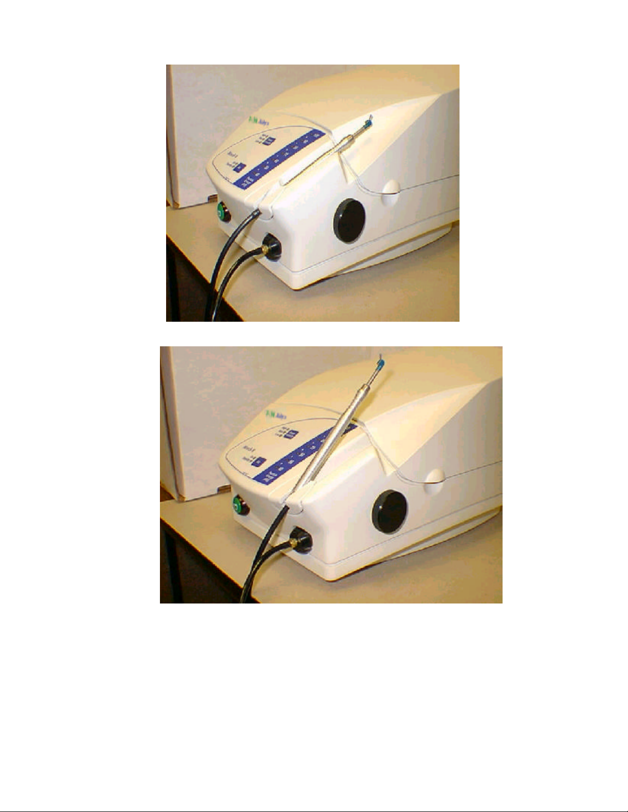
Figure 3 Hand Piece Holder in horizontal or vertical position
990277 Rev. A Page 12 of 46
Page 13
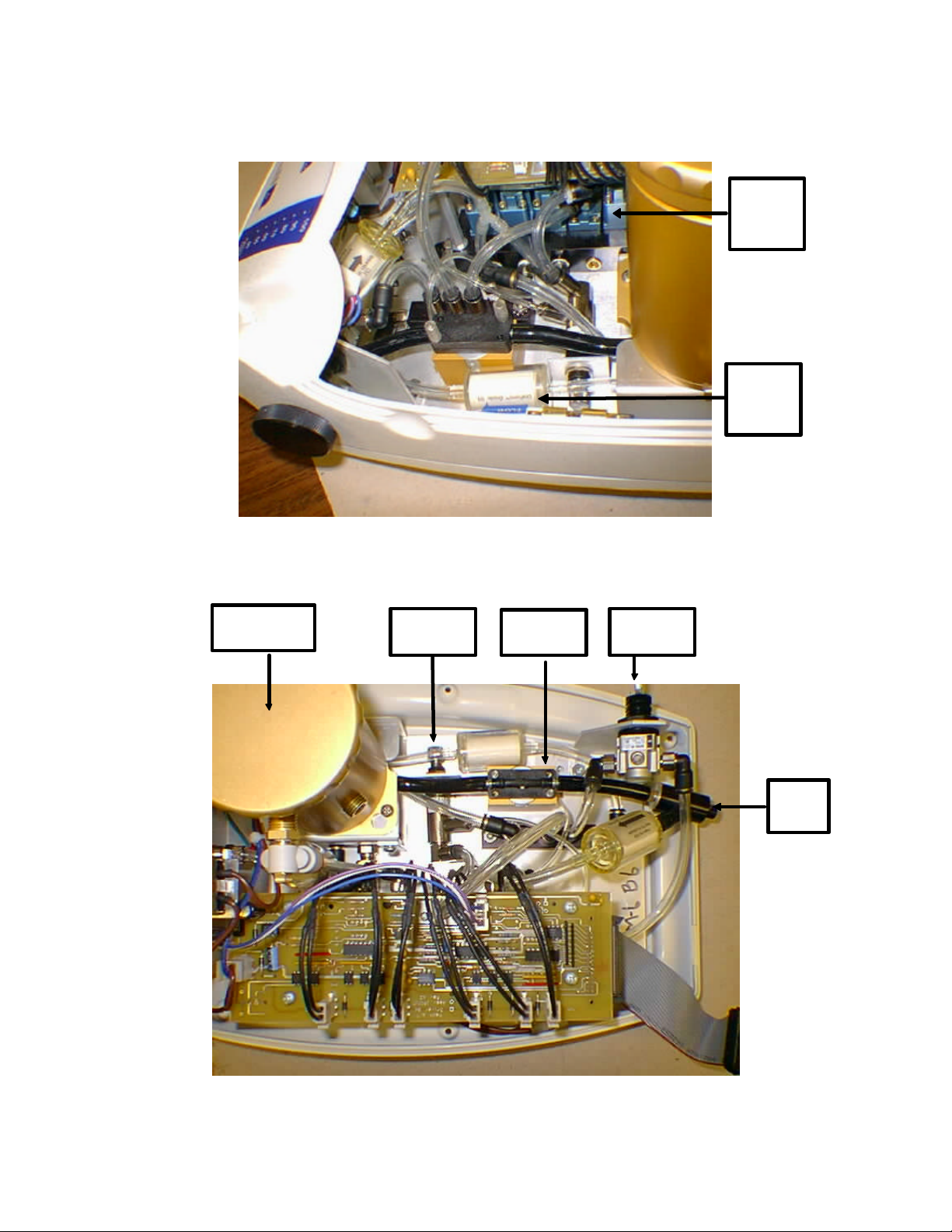
2.4 Internal Components of the Mach 6.0 (Refer to Figures 4, 5,and 6)
Solenoid
Manifold
assembly
Air In
Filter
assembly
Figure 4 Internal Components location
Powder Feed
Canister
Pinch Valve
Regulator
Pinch Tube
Valve
Pressure
Regulator
Exhaust
Catch
Figure 5 Internal Components Locations
990277 Rev. A Page 13 of 46
Page 14
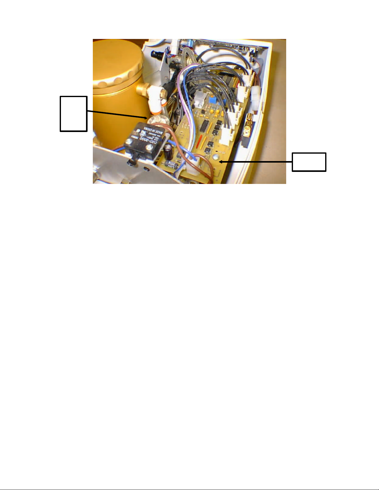
Powder
Canister
Air Out
Filter
Figure 6 Internal Components location
2.4 Pneumatic components
(Refer to Figures 4, 5, and 6)
2.4.1 Solenoid Manifold Assembly (Figure 4)
Houses all system control solenoids that control air flow, powder flow, exhaust and de-pressurization.
2.4.2 Pinch Tube Valve Assembly (Figure 5)
Solenoid
Driver PCA
Houses the pinch tube which allows the powder - air mixture to flow to the handpiece.
2.4.3 Particle Energy Pressure Regulator (Figure 5)
The System Pressure Regulator is the mechanical device which controls the desired amount of air pressure.
2.4.4 Pinch Valve Regulator Assembly (Figure 5)
Adjusted to supply a constant amount of air for closing off the Pinch tube when needed. This is adjusted for 60 PSI.
2.4.5 Powder Canister Air In Filter Assembly (Figure 5)
Consists of a Coalescing and Silica Filters for filtering particulate matter and water vapor from entering the powder
canister. Aids in the prevention of powder clogs due to moisture or particulate matter.
2.4.6 Mach 6 Manifold Assembly (Figure 4)
Series of connections for tube routing
2.4.7 Powder Canister Air Out Filter Assembly (Figure 6)
Used to allow air to escape from the top of the canister and keep particles out of the solenoid valves.
2.4.8 Exhaust Catch Assembly (Figure 5)
Used as a method to stop powder flow when the foot switch is released.
990277 Rev. A Page 14 of 46
Page 15

2.4.9 Solenoid Driver PCA
Controls all solenoids based on input from the Display Control Panel and acts as an interface for the rest of the
system.
2.4.10 Display Control PCA
Converts user input to electronic signals for use by the solenoid Valve driver PCA to control the rest of the system.
Figure - 7 Pneumatic Tubing Diagram
990277 Rev. A Page 15 of 46
Page 16

Mach 6 Air Abrasion System Block Diagram
AC Voltage
In
Air
Input
External
12 V
Power
Supp
ly
F1
F2
ON/OFF
Switch
Atmosphere
Legend
Abrasive Fluid Path
Air Path
Electrical Connection
Interlock
SwitchPower
BV1
PF5
Powder
Canister
Mixing Chamber
SV1 Reg1
31
2
CV2
D isplay Control
PCA
Pressure
Transducer
2
31
F3
2
31
Atmosphere
30 pin Ribbon
Cable
Solenoid Driver PCA
SV2
Atmosphere
SV3
CV3
2
Pinch Valve
PV1
Foot switch
Reg2
SV4
31
2
31
F4CV1
Exhaust Catch
Manifold
SV5
SV6
31
Atmosphere
2
Handpiece / Nozzle
Figure - 8 Pneumatic Block Diagram
2.5 Electrical/Electronic Components
(Refer to Figures 8 9, and 10)
2.5.1 External Power Supply
Provides 12 VDC input to the rear of the Mach 6
2.6.2 Solenoid Driver PCA (Figure – 6)
Controls all solenoids based on input from the Display Control Panel and acts as an interface for the rest of the
system.
2.5.3 Display Control PCA (Figure -8)
Converts user input to electronic signals for use by the solenoid Valve driver PCA to control the rest of the system.
2.5.4 Foot Switch
Input on/off control signal to Display Control PCA from foot switch.
990277 Rev. A Page 16 of 46
Page 17

2.5.5 Main ON/OFF Solenoid Valve (SV-1)
Controlled by the Solenoid Driver board and pressurizes the system when the ready mode is selected.
2.5.6 Feed Purge Solenoid Valve (SV-2)
Controlled by the Solenoid Driver board and is used to back flush the porous filter located in the Powder Canister.
2.5.7 Feed Solenoid Valve (SV-3)
Controlled by the Solenoid Driver board and is used to release the pressure from the canister top. When foot switch
valve opens and powder flows from canister. The longer this is open to less powder flow.
2.5.8 Pinch Solenoid Valve (SV-4)
Controlled by the Solenoid Driver board and controls the pressurization and de-pressurization of the pinch valve.
When foot switch is depressed, the valves opens and closes 3 times a second.
2.5.9 Exhaust Catch Purge Solenoid Valve (SV-5)
Used to back flush Filter 4 each time the foot switched is depressed.
2.5.10 Exhaust Catch Solenoid Valve (SV-6)
Controlled by the Solenoid Driver board and opens and closes the low resistance flow path that causes venturi effect
and stops abrasive flow to the hand piece hose and nozzle.
Figure - 9 Display and Control PCA
990277 Rev. A Page 17 of 46
Page 18

Figure - 10 Interconnect Diagram
Pinch Solenoid
Valve (SV-4)
Exhaust Catch
Valve (SV-6)
Exhaust Catch
Purge (SV-5)
Figure - 11 Solenoid Valve Manifold Assembly
Feed Purge Valve
(SV-2)
Main ON/OFF
Valve (SV-1)
Feed Solenoid
Valve (SV-3)
990277 Rev. A Page 18 of 46
Page 19

3. ROUTINE MAINTENANCE
3.1 Routine Maintenance of the Mach 6.0
Welch Allyn Kreativ Air Abrasion systems have been designed to operate with a minimum of operator attention.
Like all mechanical systems, they will operate longer and with less trouble when operator maintenance is performed
regularly. Maintenance on a Welch Allyn Kreativ Air Abrasion system is limited to cleaning, infrequent lubrication,
pinch tube replacement, and filter cartridge replacement. The maintenance procedures have been categorized by their
frequency of action and are described in this chapter with specific instructions.
3.2 Daily Requirements
3.2.1 Powder Canister
Observe the powder level in the Powder Canister, and inspect for moisture contamination. If moisture contamination
is present, the powder will not flow evenly or will appear as wet sand. Replace the powder if it is contaminated. Add
new powder, and clean the threads on the top of the canister. Remove and clean the cap gasket, and cap. Clean the
cap threads, and install the cap and tighten securely. If the cap is not secure, air leaks can occur which will affect
cutting efficiency.
NOTE : To check the powder level in the Powder Canister, turn the unit off to release the internal pressure in the
canister. If the canister is pressurized or the unit in the READY mode, the user will not be able to unfasten the cap
ring.
Complete the following procedure to empty the Powder Canister:
1. Turn the unit off to de-pressurized the system.
2. Open the top.
3. Remove the hoses connected to the canister top and bottom.
4. Remove the lid from the Powder Canister by turning the cap counterclockwise.
5. Loosen the two screws that secure the canister to the mounting bracket then turn the canister counterclockwise to disengage.
6. Empty the Powder Canister.
7. Use a brush or a vacuum to remove any powder remaining in the canister.
NOTE: It is necessary to empty the Powder Canister if the unit will be stored for a period of six weeks or
more. This will ensure that the powder is not subject to humid air conditions which may contribute to
“heavy” powder, causing the Orifice Plate Holes to clog.
Cleaning the Powder Canister:
If the Air Supply source contains moisture or other contaminants, the powder may clog the Orifice Plate Holes.
Complete the following procedure to unclog the holes:
1. Repeat the procedures for “Emptying the Powder Canister”, steps 1-7.
2. If powder is heavily contaminated, discard it. If the powder looks “heavy”, place the powder in a
microwaveable container. With the microwave set on high, cook the powder for 45 seconds. Set aside
and let cool.
990277 Rev. A Page 19 of 46
Page 20

3. Re-install the Powder Canister without the powder. Also ensure that the two screws are securely
fastened.
4. In the bottom of the canister, there are a series of five small holes. With a .0015 Endo file or an Ortho
wire, gently penetrate through the openings.
NOTE: Only remove the clogs. Too much filing will result in excess powder flow.
5. Replace the canister lid securely.
6. Ensure that the handpiece nozzle is not clogged by gently penetrating the nozzle opening with an Endo
file.
7. With the unit in the Ready position, set the “Beam Intensity” to HIGH and the Particle Energy at the
highest available pressure, point the handpiece into the KleanAir® System or vacuum. Press the
Footswitch for approximately one minute to purge the system. Return to the Standby mode.
8. Refill the Powder Canister with abrasive powder.
3.3 Weekly Requirements
3.3.1 Filters
Inspect all in-line filters for damage, presence of moisture, or color change.
3.3.2 Pinch tube
The pinch tube should be inspected for wear and tear weekly. Replace as required.
Conditions which are common when the pinch tube fails are as follows:
1. Changes in air and powder flow will result in erratic and/or poor cutting efficiency.
2. The Particle Energy may have difficulty reaching and maintaining desired setting.
3. If the pinch tubes are not replaced when failure has occurred, an audible air leak will be apparent and
abrasive powder will eventually discharge into the chassis.
4. When changing pinch tubes, the user may inadvertently neglect to get the shoe block covers secure.
Tighten the thumb screws to minimize the gap to ensure proper performance.
3.3.3 Powder Chamber
Inspect the powder chamber for moisture.
Look for powder clumps or wet powder and discard or replace as necessary.
To dry wet powder:
1. Place powder to be used in a microwave safe container.
2. Microwave on high for 45 seconds to dry the powder prior to placing in the chamber.
NOTE: Care should be taken when removing the container from the microwave, as it may be hot.
3.4 Monthly Requirements
3.4.1 Internal tubing
Inspect internal tubing for wear and air leakage.
Listen for audible leaks and look for powder accumulation internal to the unit.
Soapy water and a small paint brush are ideal for finding small leaks. Clean up excess powder to help isolate the leak
area.
990277 Rev. A Page 20 of 46
Page 21

If leaks are found, try re-seating tubing in their fittings.
If leaking persists, contact your authorized Welch Allyn / Kreativ service representative.
3.4.2 Handpieces and Nozzles
The handpieces and nozzles for the Mach 6 can be sterilized by any standard dental autoclave, ultrasonic sterilizer, or
manual sterilization practices. After removal from the autoclave, it is important to allow the nozzles and handpieces to
dry completely before use. If the handpieces and nozzles are not allowed to dry, the handpiece and nozzles may
become clogged.
If clogging occurs, complete the following procedure:
1. Remove the handpiece assembly from the handpiece hose.
2. Blow air into both the nozzle and handpiece ends.
3. If the air fails to resolve the clogging, use an Endo file or Ortho wire to penetrate the nozzle opening.
The nozzles are subject to wear and will require replacement at some point in time. Indications of wearing on the
nozzle are a decrease in cutting efficiency, an undefined stream of powder flowing from the nozzle slits along the side
of the tip.
3.5 Quarterly Requirements
3.5.1 Pinch Tubes
The Pinch tube should be replaced quarterly. A package of is supplied with each handpiece kit.
Complete the following procedure to change a pinch tube:
1. Turn the unit off. Wait until the unit has depressurized.
2. Ensure that the unit is in the OFF position and that the power cord is disconnected from the electrical
outlet.
3. Remove the Top pinch valve block cover by turning the thumb screws counterclockwise.
4. Remove the worn pinch tube by gently pulling it from the fittings. Discard the tube.
5. Insert a new pinch tube, and place the fittings and pinch tube into the bottom block indentations.
6. Replace the top block, ensuring that the fittings and pinch tube align properly. Secure the top block
with the thumb screws.
CAUTION: Failure to ensure the top and bottom block are secure will result in an air leak situation or
may potentially cause damage to the internal components.
7. Resume normal operation.
An additional factory recommendation is to inspect the shoe block covers for wear whenever a pinch tube has been
replaced. Maintenance negligence of pinch tube replacement will result in scarred shoe block covers and may
contribute to additional internal component damage, again resulting in equipment malfunction.
3.6 BI-Annual Requirements
3.6.1 Pinch Valve Assemblies
Lubricate the Pinch valve assembly to ensure proper powder delivery. A Pinch Valve Maintenance Kit (P/N 150036)
is available with all of the necessary pinch valve parts.
Complete the following procedures to lubricate the pinch valve assembly:
990277 Rev. A Page 21 of 46
Page 22

1. Turn the unit off.
2. Ensure that the unit is in the OFF position and that the power cord is disconnected from the electrical
outlet.
3. Open the Top.
4. Remove the thumb screws, turning counterclockwise to remove the top shoe block. Discard the shoe
block. Set the thumb screws aside.
5. Pull the pinch tube from its fittings. Discard the pinch tube, and inspect the fittings for wear. Replace
the fittings if necessary.
6. With a small slotted screwdriver, remove the set screws for the bottom shoe block, turning
counterclockwise, ensuring that pressure is applied to the bottom shoe block, since a spring is behind
the shoe block which may dislodge unexpectedly. Discard the bottom shoe block. Lay the set screws
aside.
7. With the bottom shoe block removed, a spring and shoe will dislodge freely.
8. Discard the shoe. Set the spring aside.
9. With a small set of needle nose pliers, remove the retaining ring. Set it aside.
10. Remove the diaphragm. Discard it .
11. Remove the piston. Remove the o-ring from the piston, and discard it.
12. Clean all parts thoroughly.
13. Install the new piston o-ring, and lightly apply lubricant around the o-ring. NOTE: Only factory
specified lubricant (Superlube) should be used.
14. Set the piston aside.
15. Thoroughly clean the internal pinch valve assembly.
16. Generously lubricate the internal piston portion of the pinch valve assembly.
17. Re-assemble pinch valve assembly.
3.7 Annual Requirements
3.7.1 Air In and Out In-Line Filters
The following in line pre-filters will need to be replaced on an annual or “as needed” basis.
1. Water Vapor Coalescing Filter K480023
2. Particulate Filter K480060
3. Absorbing Filter K480083
3.7.2 Internal Tubing
The internal tubing should be inspected for wear and for air leakage monthly. The unit internal tubing should be
replaced yearly.
3.7.3 Powder Canister
The Powder Canister cap gasket should be replaced yearly or when damage is found.
990277 Rev. A Page 22 of 46
Page 23

Maintenance Checks
No. Maintenance item 6 12 18 24
Mo. Mo. Mo. Mo.
PM 1 Maintain Pinch Valve XX XX XX XX
PM 2 Replace Filters & Tubing XX XX
PM 3 Maintain Powder Canister XX XX
PM 4 Calibrate system XX XX XX XX
PM 1. Maintain pinch valve block (Mach 6: P/N: 170179P; 6/12 Months): .50 hour
One Year Maintenance Kit K150034
Replace Components (1) K150036
Clean and lubricate pinch valve components
PM 2. Replace the Exhaust Catch and Air In/Out filter
assemblies and tubing (12 months): 1.0 hour
One Year Maintenance Kit K150034
Exhaust Catch Coalescing filter K480023
Air In Particulate filter (2) K480060
Air In Absorption filter K480083
Air Out Particulate filter K480060
Kynar “Y” K360004
Tubing, 1/16” ID (1.1 feet) K99-00200-1
Tubing, 1/8” ID (5.25 feet) K99-00200-3
Tubing, Pallethane (.55 feet) K390008
PM 3. Check Powder Canister (6/12 months): 0.5 hour
One Year Maintenance Kit K150034
Check Canister Gasket and lid
Clear powder ports and back flush canister
Clean Gasket and Canister lid
Clear and measure Orifice Plate holes
Replace powder and verify system operation
Maintain Powder Canister (12 month) 1.0 hour
Replace Canister Gasket K210207
990277 Rev. A Page 23 of 46
Page 24

Replace Orifice Plate Gasket K210082
Replace Gasket Base Cap K01-00153-1
Replace Orifice Plate K210140
Replace large super hose (black, XXX ft) K390008
PM 4. Calibrate system (6 months): 1.0 hour
Verify and calibrate using procedure in PM-4
990277 Rev. A Page 24 of 46
Page 25

PM-1 MAINTAIN PINCH VALVE BLOCK .5 hour
PARTS
1. Superlube (6 and 18 month Maintenance) K460015
2. Pinch Tube Maintenance Kit (12 and 24 month) K150036
TOOLS
1. Lint free cloth
2. #1 Flat blade screwdriver
3. Needle nose Pliers
DRAWINGS AND INSTRUCTIONS
1. Pinch Valve Body assembly KMP170179
Procedure
NOTE: If this is the 12 or 24 month PM, replace all parts
1. Disassemble pinch valve block.
2. If performing the 6 or 18 month PM, clean, inspect, and lubricate all parts. If there is any indication
of damage to the parts, replace the parts and proceed to step 6.
If performing the 12 or 24 month PM’s proceed to step 3.
3. Discard Diaphragms, “O” rings.
4. Inspect Shoe blocks, block top and bottoms. Discard block tops, bottoms, spring, piston, pinch
tube, and diaphragm.
5. Clean and lubricate pinch valve blocks and pistons.
6. Reassemble the pinch valve blocks per drawing.
7. Test and calibrate unit if required.
PM-2 REPLACE TUBING AND FILTERS (12months) 1.0 hour
PARTS
1. Exhaust Catch Coalescing filter K480023
2. Air In Particulate filter K480060
3. Air Out Particulate filter K480060
4. Air In Absorption filter K480083
5. Tubing (0.55 feet) K390008
6. Tubing (1.1 feet) K99-00200-1
7. Tubing (5.25 feet) K99-00200-3
8. Kynar Y K360004
TOOLS
1 Flat blade and Phillips screwdriver (# 2)
2 Side cutters
3 Alcohol or Leak Detect
990277 Rev. A Page 25 of 46
Page 26

4 Low pressure Air Source
DRAWINGS AND INSTRUCTIONS
1. Pneumatic Schematic K950028
Procedure
NOTE: When working with the powder, always work in a well ventilated
area.
1. Disassemble the unit to gain access to all sub-assemblies by:
a. Removing the hand piece dress nut from the front of the unit.
b. Disconnect the “On/Off switch cable at the 2 position connector.
c. Remove the Regulator knob from the right side of the unit.
d. Disconnect the 30 pin ribbon connector from the Display Control PCA.
e. Turn the unit over and remove the four phillips screws, located in the feet.
f. Remove the cover.
2. Replace the filters, Kynar “Y”, and tubing one length at a time so as not to get the
connections or paths mixed up. The tubing lengths can be found in Section 7 under each
individual sub-assembly.
3. Install cable ties and tubing clamps as required.
4. Reassemble the unit..
5. Test and calibrate unit
PM-3 INSPECT POWDER CANISTER (6 months) .5 hour
PARTS
1. None
DRAWINGS AND INSTRUCTIONS
1. KMP170180
TOOLS
1. Go/NoGo Pin Gage (.14/.16)
2. Phillips Screwdriver
3. Needle Nose Pliers
4. # 10 Endo file or Ortho wire
5. Air Source
6. Microwave Safe Dish
7. Alcohol Prep
8. Leak Detector
DRAWINGS AND INSTRUCTIONS
1. Canister Assembly KMP170180
Procedures
990277 Rev. A Page 26 of 46
Page 27

1. Place the unit in Standby condition or insert the handpiece into the holder.
2. De-energize the unit (main power switch located on the front of the unit).
3. Disconnect the power and air source from the unit.
4. Remove the canister by:
a. Removing the Pinch Tube top cover.
b. Remove the input tubing from the right side of the canister
c. Remove the outlet tubing from the Branch fitting on the upper left of the canister.
d. Loosen the 2 phillips screws
5. Remove the canister by twisting the canister and pulling upward.
6. Open the canister and pour the powder from the canister (place in a microwave safe dish
for drying).
7. Using an air source, blow out the CUP’d Porous filter from the outside in.
8. Remove the bottom of the canister removing the 3 countersink screws and removing the
bottom.
9. Clean the powder residue that may be built up on the gasket and mounting surfaces. Pay
attention as to how the rubber gasket was installed.
10. Clean off the gaskets and set aside for later use. The gaskets will be reused for the 6 month
PM and replaced for the 12 month.
11. Using a # 10 Endo file or Ortho wire, remove any debris or lodged powder from the five
holes in the bottom of the orifice plate.
12. When this is complete, reassemble the bottom of the canister.
13. Install the canister cap and connect the unit to correct power and air.
14. Energize the main power switch.
15. Remove the handpiece and place the unit into the “READY” condition.
16. Put on eye protection.
17. While holding the hand piece into an evacuation system or appropriate container for
disposal, operate the unit by manipulating the foot pedal. The unit will automatically stop
after one minute. You should pump the foot pedal and depress it continuously. You should
adjust to the maximum pressure available. This should help dislodge any possible powder
plugs the system may have developed.
18. Place the handpiece in the cradle.
19. Dry the powder out by placing in a microwave for approximately 45 seconds on high.
20. Fill the powder canister as required.
21. Reinstall the canister lid and re energize the system.
22. Test the cutting ability on a Learn-A-Prep.
23. Return the unit to ready state or repair as required.
PM-3 REPLACE CANISTER COMPONENTS (12 months) .5 hour
Follow the procedure as described above except replace the following parts
1. Orifice Plate K210140
2. Orifice Plate Gasket K210082
3. Base Cap Chamber Gasket K01-00153-1
990277 Rev. A Page 27 of 46
Page 28

4. Cover Powder Feed Gasket K210207
PM-4 Calibrate the Unit 1.0 hour
PARTS:
1. NONE
TOOLS
1. DMM (Fluke 77 or equivalent)
2. Air Pressure Gauge (0-160 PSI, 1 PSI resolution)
3. Various Pneumatic fittings
4. Small Adjustment screwdriver
5. Leak Detector (K360007)
6. TORQUE Seal (K450008)
7. Welch Allyn Kreativ 27.5 Micron Powder
8. Pin Gauges, 0.014, 0.016, 0.0175”, 0.018” & 0.0185”
9. Power Supply (12 V, 2.75 A; K590005)
10. Foot Switch Assembly, (K180086)
11. M6/7 Handpiece Hose Assembly; P/N 170210
12. Handpiece Standard Assembly; P/N 200002
13. Nozzle Assembly, Blue; P/N 170011-1
14. “T - 1”, ¼ “ T” fitting (K360030)
15. “T - 2”, ¼” x ¼” x 1/8” Reducer fitting (K360078)
16. Reducer, ¼ “ x 1/8 “ In-line reducer fitting (K360079)
DRAWINGS or PROCEDURES
MACH 6 Calibration procedure
CALIBRATION PROCEDURE:
Transducer Calibration.
1. Install a “T-1” fitting and calibrated pressure gauge inline between the pressure transducer and the
Manifold Assembly. Refer to “Leak Test Connection, Figure 12.
2. Connect clean dry air to the Mach 6 with at least 120 psi.
3. Turn power “ON” to the Mach 6 and override the interlock switch.
4. Set the DMM to measure “DC Volts” and connect the positive lead to R4 on the Solenoid Driver
PCA and the ground lead to the negative lead of C-18. Refer to Figure 13.
5. Adjust R9 on the Solenoid Driver PCA for a reading of 0.00 ± 0.01 Vdc.
990277 Rev. A Page 28 of 46
Page 29

6. Turn the unit from standby to ready, and adjust the Particle Energy to 100 psi.
7. Adjust R1 (span) on the Solenoid Driver PCA to yield a reading of 3.00 ± 0.01 Vdc (2.99 to
3.01).
8. Adjust the Particle Energy up and down to verify the pressure gauge matches the calibrated
pressure transducer. If the pressure gauge and Particle Energy display do not match, adjust R1,
and repeat this step until they are the same.
9. Turn the unit to standby.
10. Turn power “OFF”. Disconnect the air source and pressure gauge, reconnect the pressure
transducer to the Manifold Assembly.
11. Apply Torque Seal (P/N 450008) to potentiometers R1 and R9.
Pinch Valve Regulator Adjustment.
1. Insert a “T-2” and Reducer fitting and calibrated pressure gauge in the tube between the pinch valve
regulator and the “Solenoid Manifold Assembly”. Refer Pinch Tube Regulator hose on Figure 12.
2. Turn power “ON” .
3. Apply air pressure of 120 PSI to the input of the unit.
4. Place the system into the ready mode.
5. Adjust the pinch valve regulator to 60 PSI.
6. Toggle the unit from standby to ready a few times.
7. Measure the Pinch Valve Regulator pressure. If the measured pressure is 60 PSI ± 2 PSI, proceed
to step 8. If the criteria is not satisfied, repeat steps “4” through “7” until the criteria is satisfied.
8. Put the system into the standby mode.
9. Remove air pressure.
10. Remove the T” connector and calibrated pressure gauge.
11. Apply Torque Seal (P/N 450008) to Regulator Adjustment screw.
Solenoid Valve Tests.
Main On/Off Solenoid Test.
1. Turn the Unit power “ON”.
2. Remove the canister top.
3. Apply air pressure to the rear of the unit.
4. Set the unit to the ready mode.
5. Verify that air flows up through the bottom orifice plate of the canister.
6. Set unit back to standby.
990277 Rev. A Page 29 of 46
Page 30

Feed Purge Solenoid Test.
1. Clamp the tubing, use non-serrated clamping device, between the Manifold Assembly and the Air In
Filter Assembly. Refer to “Feed Purge Solenoid “ Figure 12.
2. If canister top is not removed, remove it now.
3. Place your hand over the porous filter located inside the canister.
4. Set the unit to the ready mode.
5. Verify that air flows from the porous filter located inside the canister. This air flow will only last
about 5 seconds, so if you miss the air flow turn the system back to the standby mode, and then
back to the ready mode.
6. Return the unit to the standby mode.
7. Replace the powder canister top.
8. Remove clamp from the tubing.
Feed Solenoid Test
1. Set the unit to the ready mode.
2. Ensure the hand piece is in the cradle. Remove the handpiece and push the foot pedal.
3. Verify that air flows from the “Air Silencer” on the rear of the “Solenoid Manifold Assembly”. When
the foot pedal is first pushed, there should be one long pulse and three pulses per second thereafter
while the foot pedal is pushed.
4. Release the foot pedal.
Pinch Solenoid Test
1. With the unit still in the ready mode, press the foot pedal.
2. Verify that the pinch valve solenoid, and the pinch valve is pulsing approximately three times a
second.
3. Release the foot pedal.
Exhaust Catch Purge Solenoid Test.
1. Remove the hose, refer to Figure 12, from the Solenoid Manifold..
2. With the unit still in the ready mode, press the foot pedal.
3. Verify that a burst of air flows from the port of the Solenoid Manifold that the tube was removed.
The burst will be for a short period of time each time the foot pedal is pushed. Push and release the
foot pedal a few times verify the burst of air for each push.
4. Replace the tubing, and verify it doesn’t leak by pushing the foot pedal, and using leak detector
around the connection.
990277 Rev. A Page 30 of 46
Page 31

Exhaust Catch Solenoid Test
1. Install a handpiece hose onto the Front panel connector.
2. With the unit in the ready mode, put your finger near the nozzle output, press the foot pedal for 3-5
seconds, and then release the foot pedal. When the foot pedal is released, the air coming out of the
nozzle should stop in approximately one second or less. If this happens, the Exhaust Catch
Solenoid is working properly. If air continues out the nozzle after one second, fix the problem and
retest.
Leak Test
1. Install “T-1” and a calibrated pressure gauge inline between the pressure transducer on the Solenoid
Driver PCA and the Manifold Assembly. Refer to “Leak Test Connection” on Figure 12.
2. Power up the Unit.
3. Set the unit to the ready mode.
4. Adjust the Particle Energy to 100 PSI.
5. Allow the air pressure to stabilize for 15 seconds, and verify the pressure gauge still reads 100 PSI.
Re-adjust if necessary (refer to Transducer Calibration).
6. While periodically cycling the unit, monitor the gauge for continuous drops in pressure, and apply
Leak Detector fluid P/N K360007 to every pneumatic connection in the system. Any bubbles
indicate a leak. If leaks are found fix all leaks and repeat the last two steps.
Power-Up Tests
1. Turn power “ON” .
2. Immediately after power-up, verify the following display sequences occur:
a. All LEDs and LED segments flash ON and OFF.
Powder Flow Test
1. Test operate the unit to verify unit will cut.
2. Because the powder flow is an objective item, we recommend you allow the doctor to operate the
unit and verify it is to his satisfaction. Powder Flow testing is performed at the factory using at
Beam Intensities of “Lo” and “High” with a Particle Energy of 70 PSI.
990277 Rev. A Page 31 of 46
Page 32

Exhaust Catch
Purge Solenoid
Pinch Valve
Regulator hose
Leak Test
Connection
Feed Purge
Solenoid
Figure 12 Mach 6 Test Connection Diagram
Negative lead
of C-18
Positive Lead
R-4
Offset Adjust
R-9
Gain Adjust
R-1
Figure 13 Solenoid Driver Component locations
990277 Rev. A Page 32 of 46
Page 33

4. TROUBLESHOOTING
4.1 Powder Flow Problems
PROBLEM SYMPTOM(S) SOLUTION
No powder or air from the
handpiece nozzle.
Air from the handpiece but no
powder flow.
Air and powder from the
handpiece flow for only a few
seconds then stop.
Air and powder flow continuously from handpiece even
when in the Standby mode.
Powder inside the unit
chassis.
Operational LEDs are fully
functional, but there is no
powder or air.
Operational LEDs are fully
functional.
Unit is fully operational, but
powder only flows for a few
seconds when the footswitch is
pressed.
• Change pinch tube.
Powder all throughout the unit. • Blown Pinch Tube
• The handpiece is clogged. Use an endo or
ortho wire to clear the nozzle. Disconnect the
handpiece from the handpiece hose and blow air
through it.
• No Powder
• Blown Pinch Tube
• Clogged orifice plate. Empty the powder from
the canister. With an endo or ortho wire, gently
move the wire back and forth in the small holes
in the bottom of the Powder Canister.
• Pinch Valve Piston stuck
• A pinch tube is sticking. Replace the pinch
tube.
• Pinch Valve Piston stuck
• Shoe block cover is scarred. Replace the shoe
block cover.
• Hole in Powder tubing
• Shoe block cover is scarred. Replace the shoe
block cover.
Unit Plugged into Water Contact Welch Allyn Service center for unit Repair
990277 Rev. A Page 33 of 46
Page 34

5. Installation Considerations
5.1 Site Preparation for Welch Allyn Kreativ Air Abrasion Systems
Welch Allyn Kreativ Air Abrasion systems require an external source of clean, dry, compressed air or nitrogen and a
standard 110 or 220 volt outlet. In most cases your existing dental compressor is adequate. Compressed nitrogen or
an alternative compressed air source can be used if your present office compressor cannot supply enough pressure.
Air Supply
110VAC or
220 VAC
Footswitch
Welch Allyn Kreativ Mach 6 System
(11" x 11" x 13")
Handpiece
Figure 14 Connection of the Welch Allyn Kreativ Air Abrasion
System
High Volume Evacuation system: Use of a high volume evacuation system (HVE) is necessary when using the Air
Abrasion System. Your in-office high volume evacuation system can be used. The abrasive should not damage your
system as long as it is properly maintained. Welch Allyn Kreativ KleanAir system used in conjunction with your
HVE will optimize the evacuation of any abrasive that escapes from the oral cavity as well as spray from rinsing and
gases of fumes from materials used in the preparation. (Review the KleanAir brochure for more information.)
There are three possible sources for compressed air/nitrogen available for use with the Welch Allyn Kreativ Air
Abrasion system. Review all three options to determine which is best for you.
• Option #1 Present In-Office Compressor System
• Option #2 Compact Compressor System
• Option #3 Compressed (bottled) Nitrogen
NOTE: Other bottled gases such as compressed air or CO2 are NOT usable. They contain water and oil which will
cause the system to clog and not work properly.
5.1.1 Option #1: Present In-Office Compressor System
In most cases the Welch Allyn Kreativ Air Abrasion system can use your existing dental compressor. The following
will enable you to determine if your compressor can supply the required pressures/air:
990277 Rev. A Page 34 of 46
Page 35

• Air pressure: The Welch Allyn Kreativ Air Abrasion system requires a maximum of 130 PSI and a
minimum of 80 PSI of clean, dry air. Check with your compressor service company regarding the
capability of your compressor system.
• Air Dryer System: Clean, dry air is absolutely essential for the Welch Allyn Kreativ Air Abrasion
system to operate properly. Moisture or oil in the air supply can cause clogging in the abrasive flow
path and prevent the unit from operating or cutting properly. Welch Allyn Kreativ suggests that you
have your dryer system checked and serviced prior to installation of the system. Welch Allyn Kreativ
offers a small in-line dryer/filter system that can be connected in-line with the air abrasion system if
clogging problems do occur.
• Connecting the Welch Allyn Kreativ Air Abrasion system to the office air supply: Since the proper
tools and training, as well as knowledge of how your system operates, are necessary, it is important for
your compressor service company to install the air supply connection. The Air Supply Line can be
connected at any point in the Main Air Line between the System Dryer and the Operatory Chair
Regulator (see Figure14). The most common hook up is a supply line with a “quick disconnect” fitting
so that the air abrasion system can be moved easily from operatory to operatory. A 10-foot long air
supply hose with a quick disconnect fitting on each end is provided with the air abrasion system. The
fitting is a standard size and type (Parker Company P/N #393P-4-4).
Compressor Dryer
Air Supply
to System
Quick Disconnect
Operatory
Regulator
Figure 15 Connecting Air Abrasion Unit to In-Office Air
5.1.2 Option #2: Compressor System
Welch Allyn Kreativ has designed an optional, small, quiet, and compact compressor system that is powerful enough
to supply dry, clean air. It operates on a standard 110 or 220 volt outlet. The compressor is small enough to fit in a
cabinet or under a counter. You may want to put it in a utility room and have the air supply hose run a short distance
to the Operatory. The compressor operates so quietly that one usually cannot hear it over the noise of other
equipment/instruments already in the Operatory. The system’s simple and reliable design insures minimal
maintenance.
110 VAC or
220 VAC
Compact Compressor System
(Approx. 20" x 14" x 12")
Air
Supply
Line
Air Abrasion
System
Figure 16 Connecting Welch Allyn Kreativ Compressor System
990277 Rev. A Page 35 of 46
Page 36

5.1.3 Option #3: Compressed (bottled) Nitrogen
The Welch Allyn Kreativ Air Abrasion system can operate on compressed (bottled) nitrogen. Bottles and tanks of
various sizes are readily available anywhere in the country from your dental supply company or local bottled gas
supplier. The size of the bottle you order will depend on where you decide to store it. A smaller bottle could be
placed on a small cart and moved from room to room, but being smaller, it would need to be refilled more often. A
larger bottle can be stored in one place, and supply line(s) can then be run to the operatory(s) where you plan to use
the system. How long a bottle/tank will last will depend on the size of the tank and the daily usage. You should
consider the following when looking at this option:
• Size bottles/tanks that are available
• Storage requirements
• The cost of having the bottle/tank refilled
Welch Allyn Kreativ recommends a regulator that is adjustable to no more than 130 PSI. We have tested several
regulators and have found that either of the regulators listed below to be most suitable:
• Harris Company
Regulator model 425-125-580 SI
Contact your local gas supplier.
(Available from Welch / Allyn Kreativ)
• Victor Company
Regulator model VTS 253 D
Contact your local gas supplier.
CAUTION: Other regulators will work but can be adjusted to 200 PSI or higher. Damage can occur if pressure higher
than 130 PSI is applied. Damage due to extreme over pressure is not covered by the warranty.
Regulator
Tank of
Nitrogen
Air Abrasion
System
Figure 17 Using Bottled/Tanked Nitrogen
990277 Rev. A Page 36 of 46
Page 37

5.2 Dental Chair Pneumatic Integration Instructions Mach 6.0
5.2.1 Chair Integration Kit (P/N 140058)
Air Supply Hose Assembly (P/N 170206)
• K360015 Reducer Fitting
• K360016 Quick Disconnect Male Coupler
• K99-00283-1 Tube Clamps
• K390002 Tubing 3/16 ID x ¼ OD
Pneumatic Footswitch Adapter Assembly (P/N 170205)
Pneumatic Footswitch Adapter Installation Instruction
Enclosed in the Pneumatic Footswitch Adapter kit (140045 or 140058) please find:
• Pneumatic Footswitch Adapter box (part #170199) for M5/5+ or (part #170205) for M6, 7 and 8
• Interconnect tubing assembly (part #170206)
1. Locate the pneumatic lines connected to the Dental Chair Pneumatic Footswitch.
2. Repeatedly press and release the Dental Chair Footswitch while holding the pneumatic lines. The tube you feel
pulsing is the Footswitch Return line, mark it for later reference (step 4).
3. Close the valve from the office compressor to the dental chair/unit and bleed pressure from the line.
4. Install the Tee to the Footswitch Return line from the Pneumatic Footswitch.
5. Route interconnect tubing assembly from the Tee to the Pneumatic Footswitch Adapter box. Install the male
quick disconnect into the Adapter box pneumatic port.
6. Locate the electrical connector attached to the Adapter box and connect it to the Electrical Footswitch input on
the air abrasion instrument.
7. Open the valve from the compressor to restore pressure to the dental chair/unit.
8. Check new connections for leaks.
Figure 18 Pneumatic Footswitch Adapter Schematic
990277 Rev. A Page 37 of 46
Page 38
6. Spare Parts List
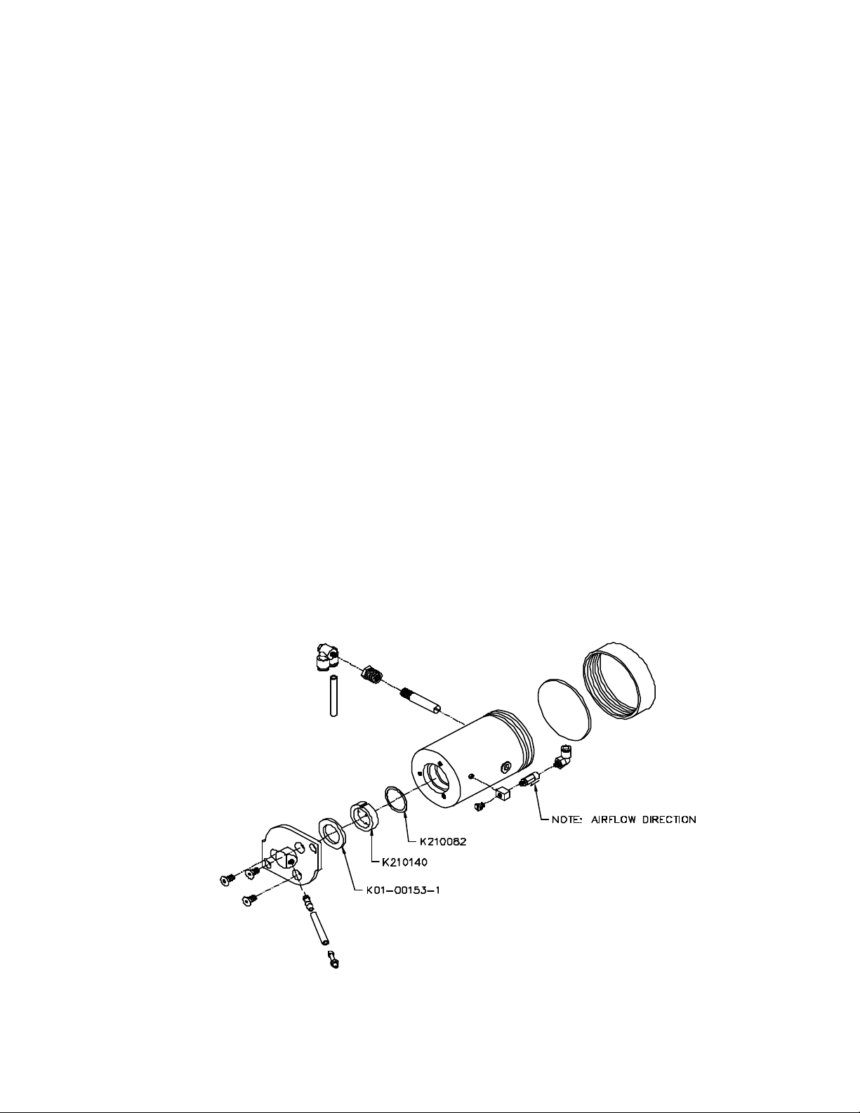
6.1 Canister Powder Feed Assembly Components
Part Number Description
K170180 Canister Powder Feed Assembly
K210140 Powder Feed Orifice Plate
K01-00172-1 Nipple Fitting Assembly
K170177 Canister Bottom Fitting Assembly
K210174 Powder Feed Canister Cover
K210207 Powder Feed Canister Cover Gasket
K01-00153-1 Gasket, Base Cap
K480089 Check Valve
K210082 Gasket, Orifice Plate
K480053 Filter Cup’D Porous
K390008 Tubing Black Pallethane (0.3 feet)
K210136 Fitting, Porous Filter Adapter
K99-00255-1 Fitting, 10-32 Nipple
K360045 Fitting, “T” x 10-32
K360038 Elbow Fitting
K99-00200-3 Clear Tubing 1/8 ID x ¼ OD (0.8 feet)
K360039 Fitting Elbow ¼ Push
990277 Rev. A Page 38 of 46
Page 39

Figure 19 Canister Powder Feed Assembly Components
6.2 Pinch Valve Components
Part Number Description
K170179 Pinch Tube Valve Assembly
K01-00164-2 Block, Bottom (*)
K01-00037-1 Block, Shoe
K99-00301-1 Spring
K01-00164-1 Block, Top (*)
K01-00155-1 Diaphragm, Pinch Valve
K01-00159-1 Gasket, Retainer
K99-00302-1 O-Ring, Pinch Valve
K99-00305-5 Pin, Dowel
K01-00152-1 Piston, Pinch Valve
K01-00168-1 Screw, Alignment for bottom block
K99-00303-1 Screw, Thumb for top block
K99-00200-1 Clear Tubing 1/16 ID x 1/8 OD
K99-00385-1 Fitting Elbow
K99-00319-3 Tube, Pinch (*)
Figure 20 Pinch Valve Components
990277 Rev. A Page 39 of 46
Page 40

6.3 Solenoid Manifold Assembly
Figure 21 Solenoid Manifold Assembly
6.4 Air In Filter Assembly (K170198)
Part Number Description
K99-00200-3 Clear Tubing 1/8 ID x ¼ OD (0.8 feet) (*)
K480083 Absorber Filter
K480060 In-Line Particulate
Figure 22 Air In Filter Assembly Components
990277 Rev. A Page 40 of 46
Page 41

6.5 Air Out Filter Assembly (K170203)
Part Number Description
K99-00200-3 Clear Tubing 1/8 ID x ¼ OD (0.3 feet)
K480060 In-Line Particulate
Figure 23 Air Out Filter Assembly Components
6.6 MACH 6 Manifold Assembly (K170202)
Part Number Description
K99-00200-3 Clear Tubing 1/8 ID x ¼ OD (1.3 feet)
K170150 5 Port Manifold Assembly
990277 Rev. A Page 41 of 46
Page 42

Figure 24 M6 Manifold Assembly Components
6.7 Exhaust Catch Assembly (K170204)
Part Number Description
K01-00172-1 Nipple Fitting Assembly (*)
K210227 Exhaust Catch Manifold
K360004 Fitting Kynar “Y”
K480023 Coalescing Filter
K99-00243-1 Brass Fitting (*)
K99-00200-3 Tubing, Urethane, 1/8” ID x ¼” OD, Clear (0.9 feet)
390008 Tubing, .095” ID x .4” OD, Black (.25 feet)k
Figure 25 Exhaust Catch Assembly Components
990277 Rev. A Page 42 of 46
Page 43
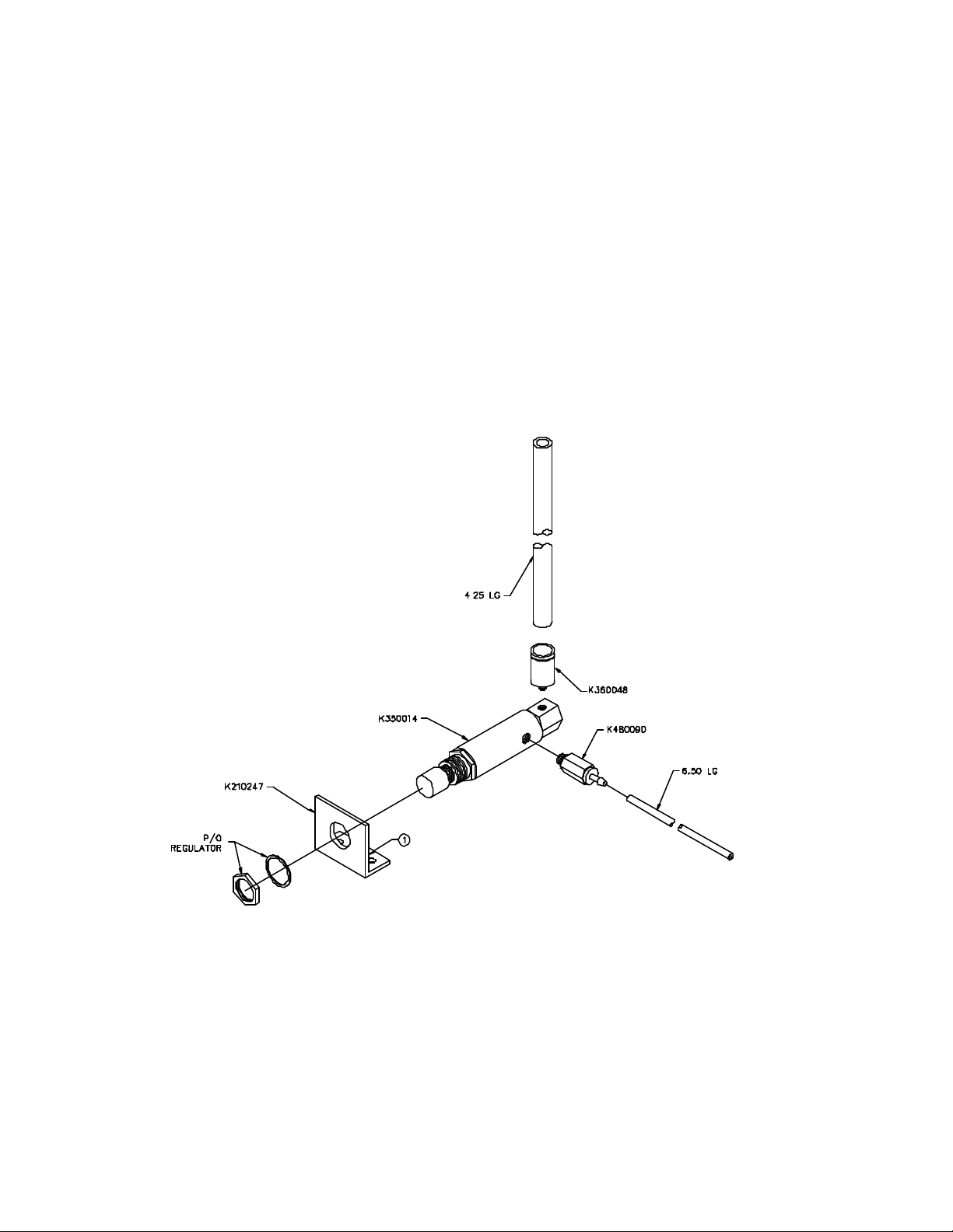
6.8 Pinch Valve Regulator Assembly (K170187)
Part Number Description
K350014 Pinch Valve Regulator
K360048 Fitting Legris Push
K210247 Pinch Valve Regulator Bracket
K480090 Check Valve
K99-00200-1 Tubing, Urethane, 1/16” ID x 1/8 ” OD, Clear (0.6 feet)
K99-00200-3 Tubing, Urethane, 1/8” ID x ¼” OD, Clear (0.4 feet)
Figure 26 Pinch Valve Regulator Assembly Components
990277 Rev. A Page 43 of 46
Page 44

6.9 System Regulator
Part Number Description
K170181 Pressure Regulator assembly
K360038 Fitting Elbow
K350008 Regulator
K99-00200-3 Tubing, Urethane, 1/8” ID x ¼” OD, Clear (1 foot)
K210211 Regulator Bracket
Figure 27 System Regulator Assembly Components
6.10 Tubing
Part Number Description
K99-00404-1 Tubing, Super Hose, Black
K99-00200-2 Tubing, Urethane, 3/32” ID x 5/32” OD, Clear
K99-00200-1 Tubing, Urethane, 3/32” ID x 5/32” OD, Clear
K99-00200-3 Tubing, Urethane, 1/8” ID x ¼” OD, Clear
390008 Tubing, .095” ID x .4” OD, Black
6.11 Accessories, Handpieces, Nozzles & Other
Part Number Description
K99-00243-1 Fitting, Coupler, 10/32” NPT x 1/8” Barb, Brass
K200002 Assy, Handpiece, Standard
K01-00211-1 Tool Kit
K01-00325-1 Kit, Pinch Tube
K170011-1 Nozzle, Blue, 45°, .018/46
K170011-2 Nozzle, Blue, 67°, .018/46
K170011-3 Nozzle, Blue, 90°, .018/46
K180086 Footswitch Assembly
K590005 Power Supply Assembly
990277 Rev. A Page 44 of 46
Page 45

K99-00002-1 Goggles, (3 Pack)
K01-00058-1 Hose, Air Supply, 10’
K210281 Barb, Handpiece Extension (*)
K370027 “O” ring for Handpiece Extension (*)
140008 Powder, Gamma Pure, 27.5 micron, gray
140013 Powder, 27 micron, white
140014 Powder, 34 micron, white
140012 Powder, 50 micron, white
600105 Power Cord, 115VAC
990155 Manual, Operators, Mach 6.0
6.12 Adhesives
Part Number Description
450000 Locktight, 680, Permanent Connection
460015 Lubricant, Superlube (*)
K99-00297-1 Pneumatic Sealant, High Pressure Connections
450008 Seal, Torque, Anti-Sabotage Inspectors
K99-00271-1 Tie Cable, Wire Holder
K99-00100-1 Tie Cable, Small
K99-00100-2 Tie Cable, Large
6.13 Chassis Components
Part Number Description
K170182 Hand Piece Holder
K180096 ON/OFF Cable Assembly
K170185 MACH 6 Case
K480084 Bumper Feet
6.14 Electrical/Electrical Components
Part Number Description
K190016-1 Display Control PCA
K190017 Solenoid Driver PCA
6.15 Shipping Accessories
Part Number Description
K470052 Accessory Box
K470104 Packaging Kit
6.16 Maintenance Kits
Part Number Description
K360078 Fitting, Union “T” Maintenance item
K360079 Fitting, Reducer ¼ “ x 1/8” Maintenance item
K140070 Technicians Manual Kit
K140058 Kit, Chair Integration
K150036 Kit, Pinch Valve Maintenance (*)
K150034 Kit, Year Maintenance, Mach 6.0
All Item with an asterisk (*) are recommended on hand spare parts.
990277 Rev. A Page 45 of 46
Page 46

7. Warranty, Returns and Adjustments
7.1 Returns and Adjustments
Warranty claims must be made promptly and received by your nearest authorized service representative during the
warranty period. The liability of Welch Allyn Kreativ, under valid warranty claims, is limited to repair or replacement
at the purchaser’s authorized service center or the purchaser’s place of business, at the option of the authorized
service representative. If it is necessary to return a product for repair or replacement, authorization for the return
must first be obtained from the authorized service representative.
All products returned for examination or warranty repair must be sent insured via a means of transportation specified
by the authorized service representative.
Welch Allyn Kreativ, or its authorized service representative claims the sole responsibility for determining the cause
of any instrument failure.
7.2 Limited Warranty
Welch Allyn Kreativ, warrants the equipment to be free from defects in material and workmanship for a period of 12
months from the date of shipment. Damage due to failure of customer to perform required user/preventative
maintenance is not warranted. Certain components having limited life expectancy (handpieces, nozzles, tubing, and
pinch tubes) are not warranted against normal wear and tear or customer damage. This limited warranty applies only
to the original purchaser/user of the equipment.
The foregoing limited warranty is exclusive and in lieu of all other warranties, whether written, oral, or implied, and
shall be purchaser’s sole remedy and Kreativ’s sole liability under contract or warranty or otherwise for the product.
Welch Allyn Kreativ , disclaims any implied warranty of merchantability or fitness for particular purposes. In no
event shall Welch Allyn Kreativ , be liable for any incidental or consequential damages, or for any incidental or
consequential damages arising out of, or in connection with, the use or performance of the product delivered
hereunder.
7.3 Storage And Shipment
The Welch Allyn Kreativ Model Mach 6.0 has been designed for long term storage in normal dental office
environments. If it is to be stored for any reason for a long period, it should be covered to protect it from adverse
conditions and the Powder Canister should be emptied. The area it is to be stored in should meet the Environmental
Limitations Transport and Storage Requirements indicated in Section 1.7, “System Specifications”.
The unit has been designed for shipment by normal commercial carriers. Protective packaging should be used, and
the original packing materials should be reinstalled for shipment. Shipping instructions must be followed closely.
The customer will be responsible for damage resulting from improper packing.
990277 Rev. A Page 46 of 46
 Loading...