

Page 1
Mach 5.0 and Mach 5.0 PLUS
Kreativ Menu
Manuals
Service Manual
Air Abrasion Units
Instructions for Use
Please read this manual thoroughly
prior to first use
CAUTION: This device must only be
purchased by, or sold to, a licensed dentist.
Manufactured by
Kreativ, Inc. (USA)
7360 Carroll Road
San Diego, CA 92121
Copyright Notice:
Copyright © 1999, Kreativ, Inc. All rights reserved. No part of this manual may be
reproduced without written permission from Kreativ, Inc.
European Authorized Representative
Welch Allyn LTD.
Navan, Co. Meath
Republic of Ireland
Ph: 353-46-79060
990008 Rev. H
Page 2

TABLE OF CONTENTS
1. INTRODUCTION AND GENERAL INFORMATION 4
SPECIFICATIONS 6
2. SAFETY 8
WARNINGS 8
CAUTIONS 8
SAFETY MARKINGS ON LABELS 10
3. CONTROLS AND CONNECTORS 11
ITEM DESCRIPTIONS 11
CONTROL PANEL 12
DRAWINGS OF CONTROLS 13
FUNCTIONAL DESCRIPTION 15
4. UNPACKING AND SETUP 17
GENERAL INFORMATION 17
UNPACKING AND SETUP 17
AIR SUPPLY REQUIREMENTS (M ACH 5.0 ONLY) 18
ELECTRICAL REQUIREMENTS 18
MACH 5.0/D ENTAL CHAIR PNEUMATIC INTEGRATION 18
5. INSTALLATION AND UNIT CHECKOUT 20
PRE -INSTALLATION REQUIREMENTS 20
UNIT CHECKOUT 20
FILLING THE MIXTURE CHAMBER 21
OPERATIONAL CHECKOUT 22
FOOTSWITCH OPERATION 22
UNIT SHUTDOWN 22
MIXING CHAMBER POWDER UNLOADING 22
6. STERILIZATION PROCEDURES 24
HANDPIECE 24
HANDPIECE CRADLE 24
ACCESSORIES 24
POWDER 25
7. ROUTINE MAINTENANCE 26
DAILY REQUIREMENTS 26
WEEKLY REQUIREMENTS 26
MONTHLY REQUIREMENTS 27
8. TROUBLESHOOTING 28
TROUBLESHOOTING TIPS 28
Page 2 990008 Rev. H
Page 3

ERROR CODES 30
9. HANDPIECES/NOZZLES AND ABRASIVES 31
STANDARD NOZZLES 31
SUPERSONIC TURBO (SST) TIPPED HANDPIECE ASSEMBLIES 31
ABRASIVES, GAMMAPURE
®
(GAMMA TREATED) 31
ORDERING INFORMATION 32
10. RECYCLING 34
RECYCLING INSTRUCTIONS FOR DEVICE, ACCESSORIES AND PACKAGING 34
ENVIRONMENTALLY RELEVANT MATERIAL 34
11. WARRANTY, RETURNS AND ADJUSTMENTS 36
RETURNS AND ADJUSTMENTS 36
LIMITED WARRANTY 36
STORAGE AND SHIPMENT 37
Page 3 990008 Rev. H
Page 4

1. Introduction and General Information
1
Introduction
The Kreativ Mach 5.0 and Mach 5.0 PLUS systems are compact, highly reliable, stateof-the-art instruments designed for Air Abrasive MicroDentistry. They are designed as
a means of removing tooth structure and other materials to prepare teeth for restoration,
and as an adjunct to the high speed dental handpiece and bur. These instruments were
developed after extensive consultation with dentists in order to provide the optimum
performance, taking into consideration patient comfort and the time constraints faced by
today’s 21st Century dental office.
Chapter
Note: Clinical use of the Kreativ Mach 5.0 and Mach 5.0 PLUS air abrasion systems
for procedures not included or suggested in this instruction guide is not advised.
Similarly, the Kreativ Mach 5.0 and Mach 5.0 PLUS systems should be only used by
dental professionals who have practiced on extracted teeth and who are thoroughly
familiar with this manual.
Purpose of this Manual
This manual should be thoroughly studied before installing and using the equipment.
Please call your nearest authorized Welch Allyn / Kreativ service representative if you
need additional information regarding installation, operation, or service of the instrument.
Information essential to the installation, operation, and routine maintenance of the Mach
5.0 and the Mach 5.0 PLUS devices manufactured by Kreativ, Inc., is included in this
manual. The instructions are written specifically for personnel who have been trained in
restorative and preventive dentistry.
A full selection of abrasive powders and nozzle sizes are available from your nearest
Welch Allyn / Kreativ sales representative. See the listing of supplies in Chapter 8.
All serviced components, such as control valves and hose connections, can be easily
accessed through the side doors of the instrument. A footswitch is provided to start the
powder flow. The instrument features a mixing chamber which can be quickly unloaded
in order to facilitate service, changing abrasive powders, or cleanup of the unit after use.
Page 4 990008 Rev. H
Page 5

General Information and Features
The Kreativ Mach 5.0 and Mach 5.0 PLUS systems are designed to provide controlled
flow of an abrasive powder and air mixture through a very precise nozzle. Applications
include amalgam removal, cutting, abrading, deburring, peening and etching of tooth
structures and other materials. Features of the Mach 5.0 and the Mach 5.0 PLUS air
abrasion systems include:
Operating Modes
• PowerPulse™ - optimized to remove amalgam
• MicroPulse™ - for removal of tooth structure
• Continuous - for microetching procedures
Remote Control
• Continuously Variable levels controlled by the user:
• Particle Energy (minimum is 30, maximum is 120), see Table 1 for psi-
to-kPa conversion in Chapter 3
• Beam Intensity (minimum powder is 0, maximum is powder 10)
• Remote Control module can be attached to dental units via an extension cable
• Easy to read LED display
• Visual and audible indicators
• Diagnostic/maintenance reminders
• Replace pinch tube in Pinch Valve #1
• Service Needed
• Powder Low
• Replace pinch tube in Pinch Valve #2
• Empty Exhaust Bottle
• Input Error
• Handpiece holder (bracket with sensor)
Interfaces with Dental Unit
• Remote Control offers movement of the control panel to the location of the
dentist’s choice, usually near other handpieces
• Keeps all controls at your fingertips
• Seamless integration of air abrasion with traditional dental instruments
Page 5 990008 Rev. H
Page 6

Full Diagnostic
• At start-up
• Continuous monitoring
Additional Features
• Quickly detachable handpiece for easy sterilization
• Double doors for simplifying preventive maintenance
• Exhaust bottle container
• Easy pinch tube replacement
• Easy access to powder canister
• Accessory drawer for nozzles, handpieces, etc.
• Full range of operation from 30 psi to 120 psi
• Convenient handles
• Mobility
• Wide range of nozzles in sizes/angles and cutting capabilities
• Locked doors to prevent unauthorized access
Specifications
• Power Requirements: Domestic
• Air Requirements: Mach 5.0, 80 to125 psi (550 to 860 kPa) with
Mach 5.0 100-127 V~, 60 Hz, 400 mA
Mach 5.0 PLUS 100-127 V~, 60 Hz, 6.5 A
International
Mach 5.0 220-240 V~, 50 Hz, 170 mA
Mach 5.0 PLUS 220-240 V~, 50 Hz, 3.5 A
NOTE: Verify unit has correct voltage for your
application.
at least 1.5 cfm (42.5 l/min) recommended; the
supply pressure must be at least 5 psi (35 kPa)
greater than the selected operating pressure.
The Mach 5.0 PLUS incorporates a built-in
compressor which has an automatic thermal
Page 6 990008 Rev. H
Page 7
cut-out if the head reaches approx. 212° F
(100° C), and a thermal cut-in when the
temperature drops to 140° F (60° C).
• Approximate Size: Mach 5.0, 12” x 18” x 8.5”
(30.4 x 45.7 x 21.5 cm)
Mach 5.0 PLUS, 25” x 18” x 8.5”
(63.5 x 45.7 x 21.5 cm)
• Approximate Weight: Mach 5.0, 30 lbs. (15.9 kg)
Mach 5.0 PLUS, 85 lbs. (38.6 kg)
• Environment Limitations: Operational Requirements:
Temperature: 50° F to 95° F (+10° C to 35° C)
Humidity: 30 % to 75 %
Atmospheric pressure range: 10.15 psia ( 70 kPa) to
Transport and Storage Requirements:
Temperature: 14° F to 122° F (-10° C to 50° C)
Humidity: 10 % to 90 %
Atmospheric pressure range: 7.25 psia ( 50 kPa)
15.37 psia (106 kPa)
to 15.37 psia (106 kPa)
• Equipment Classification: The Mach 5.0 and Mach 5.0 PLUS systems are
Class I devices requiring an electrical earth ground.
These devices are classified as ordinary with regard
to protection against water ingress.
• Electrical Fuses: Littelfuse, SlowBlow
Model Fuse Mfr Mfr P/N Kreativ P/N Fuse Rating
Mach 5 115V Littelfuse Type 326-001 600089 1A, 250Vac
Mach 5+ 115V Littelfuse Type 326-010 600071 10A, 250Vac
or Bussmann Type MDA-10 600071 10A, 250Vac
Mach 5 230V Littelfuse Type 218-01.6 600096 1.6A, 250Vac
Mach 5+ 230V Littelfuse Type 218-06.3 600112 6.3A, 250Vac
• UL Canadian Classification Marking:
Air Abrasive Micro Dentistry Device, Model 9000-XX
(where XX can be any alphanumeric character)
WITH RESPECT TO ELECTRIC SHOCK, FIRE, MECHANICAL
Page 7 990008 Rev. H
Page 8

2. Safety
2
The Kreativ Mach 5.0 and Mach 5.0 PLUS systems are designed for use only by and
on the order of a dentist.
Warnings
Always wear protective eye equipment in order to avoid corneal abrasion or irritation if
particles are deflected into the eye. This applies to the dentist, staff, and patient.
A rubber dam is recommended in order to avoid injury to gingiva or other soft tissue,
and for interproximal preparations to protect adjacent tooth surfaces.
AND OTHER SPECIFIED HAZARDS ONLY
IN ACCORDANCE WITH CAN/CSA C22.2 NO. 601.1
21ZJ
Chapter
Never direct the handpiece to an open pulp chamber or at pulpal exposures. Also
never place the handpiece in direct contact with the gingiva when the air pressure is
activated. While the abrasive stream will not cut the gingival tissue, it may irritate it.
All Kreativ Mach 5.0 and Mach 5.0 PLUS accessories which come into contact with
the patient should be sterilized prior to each use. Always disinfect the handpiece cradle
in the remote control unit before each patient use.
Always use your high volume evacuation system when using the handpiece of the
Kreativ Mach 5.0 or Mach 5.0 PLUS. Have the dental assistant place the high volume
evacuation system in close proximity to the operative site.
Make sure that the Kreativ Mach 5.0 and Mach 5.0 PLUS systems are connected to a
properly grounded electrical outlet.
Always replace fuses with fuses of the proper rating, as indicated in the Chapter 1.
Cautions
For dental cleaning (prophylaxis) procedures, be absolutely sure that the
chamber and hose have been completely cleared of all abrasive powders and use
only bicarbonate in the chamber.
Page 8 990008 Rev. H
Page 9

The handpiece should be directed precisely at surfaces and tooth structures which are
to be modified or removed. The nozzle tip should be placed a few millimeters from the
tooth and angled toward the area to be removed or modified. Unlike the high speed
handpiece, the Mach 5.0 nozzle cuts only directly from the end; there is no side cutting.
Do not attempt to service the unit beyond those items described in the maintenance
section. Call your nearest Welch Allyn / Kreativ service representative for instructions.
Practice on extracted teeth prior to utilizing the Mach 5.0 and Mach 5.0 PLUS on
patients. Begin with the 27.5 micron aluminum oxide powder. Use only short bursts,
carefully monitoring your progress. Most users prefer the 27.5 micron powder at a
Particle Energy setting of 50 to 80 psi due to improved patient acceptance.
Do not substitute non-Kreativ, Inc., materials or accessories. Use of materials or
accessories supplied by other manufacturers may result in damage to the unit and will
void the factory warranty.
Use only clean dry air. Make sure that your air compressor system utilizes air dryer
filter systems and that they are fully operational. Any moisture or oil in the air supply
will adversely affect the performance of your Mach 5.0 or Mach 5.0 PLUS.
When using the Mach 5.0, check to be sure that your air system produces at least the
minimum pressure and flow rate indicated in the Air Requirements section of the
Specifications in Chapter 1.
Sound clinical judgment, good common sense and proper training are essential to the
successful use of the unit in order to provide safe and efficient patient care.
Always follow “standard of care” protocols in performing dental operative procedures.
The handle on the top of the Mach 5.0 PLUS units is intended to be used to pull the
units and is not meant for picking up the units.
Caution: Connecting the instrument’s input air supply line to a water outlet will
lead to damage to the instrument which is not covered under the limited
warranty. Repairs for such damage are at the customer’s expense.
Page 9 990008 Rev. H
Page 10
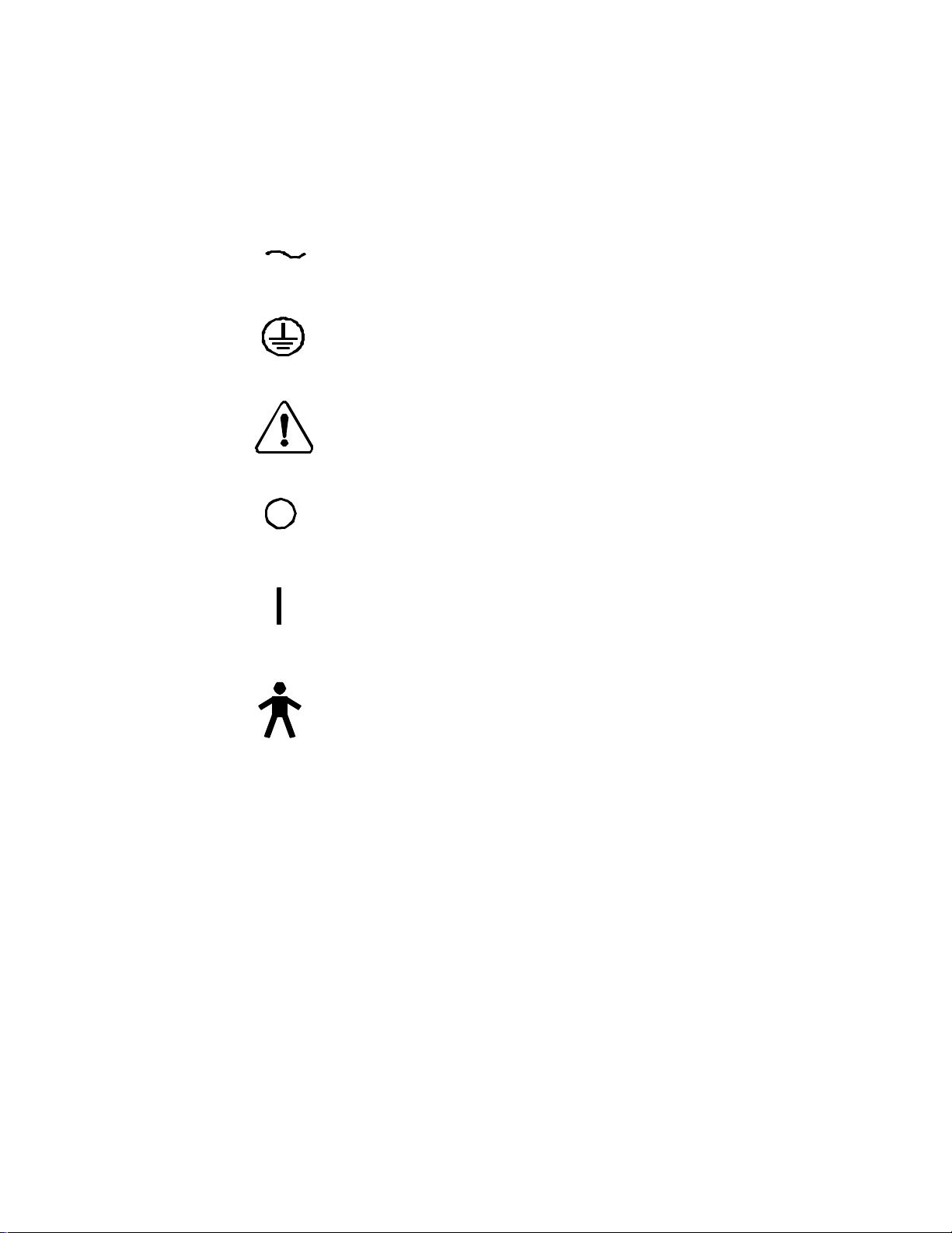
Safety Markings on Labels
Alternating current
Protective earth (ground)
Attention, consult accompanying documents
Off (power: disconnection from the mains)
On (power: connection to the mains)
Type B equipment (defines the degree of protection against
electrical shock)
Page 10 990008 Rev. H
Page 11

3. Controls and Connectors
3
The diagrams on the following pages illustrate the external controls, indicators, and
connectors for the Kreativ Mach 5.0 and Mach 5.0 PLUS instruments.
In both the Mach 5.0 and the Mach 5.0 PLUS, the handpiece hose connects to a
connector located under the Control Module.
The Control Module is removable from the front of the Mach 5.0 and the Mach 5.0
PLUS and can be attached to the Dental unit, as follows:
1. The Control Module is held to the front of the instrument by spring tension on the
interconnecting cable. With the handpiece mounted in the cradle on top of the
Control Module, the hose and the provided extension cable allow the Control
Module to be remotely located up to 10 feet from the main unit. The connector to
the air supply is located on the rear of the instrument.
Chapter
2. A mounting plate with clamp is supplied with the Mach 5.0 and the Mach 5.0
PLUS, to be mounted on the dental unit.
3. The Control Module will attach to the mounting plate for use at the dental unit,
remotely from the main instrument.
Item Descriptions
Refer to the Drawings in this section for the following items.
(1) On/Off Power Switch: turns power on or off to the entire instrument
(2) Power Cord Connector: connection point for the power cord.
(3) Fuse Box: the location of the instrument fuses. Always replace with the same
type of fuse with the same rating, indicated in Chapter 1.
(4) Pneumatic Footswitch Connector: connection point for the dental chair
pneumatic footswitch.
(5) Electric Footswitch Connector: connection point for the electrical foot-switch
Page 11 990008 Rev. H
Page 12

(6) Air Supply: connection point for the office air supply to the instrument (Mach
5.0 only)
Control Panel
Air Indicator: indicates the status of the air pressure as “On” or “Standby”
Mode: indicates the operating mode of the instrument as “PowerPulse,”
“MicroPulse,” or “Continuous.” The power up default is PowerPulse
Beam Intensity: indicates the relative amount of abrasive powder that is being
delivered to the handpiece nozzle
Warning Indicators: indicate the type of problem when operational problems occur
Particle Energy: indicates the pressure with which the abrasive powder is being
delivered. Numbers in the display indicate Pounds per Square Inch (PSI).
Conversion Table of PSI to kPa
PSI kPa PSI kPa
30 210 90 620
35 240 95 655
40 275 100 690
45 310 105 725
50 345 110 760
55 380 115 795
60 415 120 825
65 450 125 860
70 485 130 895
75 515 135 930
80 550 140 965
85 585
Table 1
Page 12 990008 Rev. H
Page 13

Drawings of Controls
Figure 1
Page 13 990008 Rev. H
Page 14

Figure 2
Page 14 990008 Rev. H
Page 15

Functional Description
When the unit is initially turned on, all lights on the Control Module will light and the
Beam Intensity and Particle Energy windows will show “8.8.8.” until the diagnostics are
complete (indicating the unit is ready to operate). The values shown will be the previous
settings used.
Kreativ Mach 5.0 and Mach 5.0 PLUS systems provide a controlled mixture of
powder particles in a dry air stream and delivers this mixture through a nozzle.
Three primary paths are provided for the air supply within the unit. One is to the
Exhaust Control Valve, another to the Abrasive Control Valve, and the third is through
the Mixing Chamber and the Abrasive Control Valve Tube to the nozzle. In the mixing
chamber, the stream of dry air is mixed with powder particles.
When the Air switch is set to “On”, the On/Off Air Valve Switch allows the air to flow
to the Mixing Chamber. With the footswitch depressed, the Abrasive Control Valve is
opened. This opens the path for the stream of powder particles from the Mixing
Chamber to the nozzle. The Beam Intensity and Particle Energy can be adjusted to
provide optimum powder flow.
The air stream combined with abrasive powder has the ability to cut and etch tooth
structure and ceramic. The abrasive powder/air stream is directed through a light,
flexible hose to the handpiece for precise cutting. Various nozzles and handpieces are
offered with different orifice sizes and angles to enable the practitioner to accomplish
specific tasks. In addition, a selection of abrasive powder is available. Nozzle and
abrasive powder types are listed in Chapter 9.
CAUTION: The unit should only be powered down with the Air control in
“Standby” mode.
NOTE: The unit will automatically go into “Standby” if left unattended for approximately
10 minutes.
When the Power switch is set to Off, the unit automatically bleeds off the internal air
pressure.
WARNING: Do not attempt to open the doors of the unit with power turned on!
Page 15 990008 Rev. H
Page 16

Page 16 990008 Rev. H
Page 17

4. Unpacking and Setup
4
General Information
SAVE THE CARTON!
The Mach 5.0 and Mach 5.0 PLUS and all accessories are shipped in a single
container. When unpacking, check items against the packing list included with the unit.
The shipping container and packing materials should be retained in the
unlikely event that the instrument has to be returned to the factory for service
or repair.
Chapter
To operate the Mach 5.0, the unit requires an external source of either clean, dry,
compressed air, or nitrogen together with a properly adjusted pressure regulator. For
additional information consult your Kreativ, Inc. dealer.
The Mach 5.0 PLUS instrument has a built-in air compressor, thus eliminating the need
for connection to an external air supply.
It is necessary to connect to a properly grounded electrical outlet.
Unpacking and Setup
Remove the Mach 5.0 or the Mach 5.0 PLUS unit from the shipping container and
proceed as follows:
• Unlock and open the left side door gently.
• Remove the foam packing (2 pieces) which prevents the vibrator from moving
during shipping. Retain the foam with the shipping box and packing materials. If the
unit is to be shipped again, the vibrator support foam packing should be reinstalled
to prevent possible damage to the vibrator and its mounts.
CAUTION: Failure to remove the foam packing will result in improper vibrator
operation and powder flow.
Page 17 990008 Rev. H
Page 18

• On Mach 5.0 PLUS only, remove the black plug from the air inlet on top of the
compressor module, and replace with the included filter.
CAUTION: Failure to replace the black plug with the filter will result in low air
condition, and damage to the compressor unit.
WARNING: The use of compressed oxygen as a gas supply for the unit
presents the possibility of having a gas that supports flammability. Under
NO circumstances should oxygen be used.
Air Supply Requirements (Mach 5.0 only)
For the Mach 5.0 only, be sure that the supplied air pressure and air flow volume to the
unit meet the minimum Air Requirements indicated in the Specifications section in
Chapter 1. Moisture filters must be used since compressed air lines may be
contaminated with moisture, oil or dirt, which are detrimental to the performance and
operation of the unit. Kreativ can supply a product (the Klean Pak) to assure a dry air
supply.
Caution: Connecting the instrument’s input air supply line to a water outlet will
lead to damage to the instrument which is not covered under the limited
warranty. Repairs for such damage are at the customer’s expense.
Electrical Requirements
Reference the Specifications section of Chapter 1 of this manual for the power
requirements of the unit. The power requirements of your instrument are located on the
system label on the back cover of the instrument. Verify the unit is set up correctly for
your electrical supply. When replacing fuses, only use fuses supplied by Kreativ in your
customer kit. If your requirements are different, consult Kreativ, Inc., or your dealer
before operating this instrument.
Mach 5.0/Dental Chair Pneumatic Integration
Please refer to Figure 3.
1. Depress chair foot switch while holding foot switch air line. The tube you feel
pulsing is the “foot switch return” line, mark it for later reference (step 5).
2. Close valve from office compressor to dental chair/unit and bleed pressure from
line.
3. Install “Tee 1” on line from compressor to dental unit before the regulator.
Page 18 990008 Rev. H
Page 19

4. Route line from “Tee 1” to Mach 5.0. Install female quick disconnect to end and
connect to Mach 5.0 “Air In” port.
5. Install “Tee 2” on return line from foot switch.
6. Route line from “Tee 2” to Mach 5.0. Install male quick disconnect to end and
connect to Mach 5.0 “Foot Switch” port.
7. Open valve from compressor to restore pressure to the Dental chair/unit.
8. Check new connections for leaks.
Caution: When used in this manner, it is important to return the handpiece to
the holder prior to using other devices.
*Not required for the Mach 5.0 PLUS with compressor.
Figure 3 - Dental Chair Pneumatic Integration Diagram
Page 19 990008 Rev. H
Page 20

5. Installation and Unit Checkout
5
After completing the instructions in Chapter 4 you are now ready to install your Kreativ
Mach 5.0 or Mach 5.0 PLUS. Refer to the drawings and descriptions in Chapter 3 for
the identification of the external controls and connections.
Pre-Installation Requirements
• Adequate Air Supply, Mach 5.0 only. The most convenient set up will be to
integrate the Mach 5.0 into your Dental unit as explained in the previous section. If
you choose to hook up to your in-office air do the following:
Chapter
1. Ensure that you have at least the minimum air pressure and air flow volume of
clean, dry air (see Chapters 1 and 4 for Air Supply Requirements). Refer to the
Site Preparation information supplied by Kreativ. Ideally, air for the Mach 5.0
will be obtained by placing a "Tee" fitting prior to the final regulator at the
operatory, but after the dryer, traps and various filters.
2. If clean, dry air of adequate pressure and volume is not available, Kreativ
recommends using compressed Nitrogen with a regulator (Follow integration
instructions).
• Power supply/earth grounding. Note: route the power cord safely out of the way
and do not use an extension cord.
Unit Checkout
• Set the Power Switch on the back of the instrument to OFF.
• On the Mach 5.0, connect the end of the air supply hose with the quick disconnect
to the external air supply.
• Plug the power supply cord into a properly grounded receptacle.
• Set the Power Switch on the back of the instrument to ON. The Control Module
should now be illuminated.
Page 20 990008 Rev. H
Page 21

When first turned on, all lights on the Control Module will flash until the diagnostics are
complete, indicating that the unit is ready to operate. The values shown will be the
values from the last operation.
CAUTION: If the Control Module does not illuminate, it indicates absence of
electrical power. Verify that power is available and the fuses are correct. If
the Control Module still does not illuminate, call your nearest authorized Welch
Allyn / Kreativ service representative.
• Verify that a handpiece/nozzle is attached to the delivery hose.
• Plug the hose assembly into the front of the unit.
• Lift the handpiece from its cradle and actuate the footswitch. Air should flow from
the nozzle. Do not actuate the footswitch while the handpiece is in the cradle.
WARNING! Some residual powder may be in the unit from factory testing.
Always use goggles or protective eyewear when using the Kreativ Mach 5.0 or
Mach 5.0 PLUS systems and do not direct the nozzle towards the face when
operating the footswitch.
WARNING! Before filling the mixing chamber, with the Air Control Switch in
STANDBY, set the Power Switch on the back of the instrument to OFF. This
depressurizes the system.
• • Select the desired powder for the operation to be performed and proceed to fill the
mixing chamber as described in the following section.
Filling the Mixture Chamber
The unit must be powered down as described above. Failure to do so will prevent the
removal of the mixing chamber lid.
• Using the key, open the door on the left side of the instrument as you face the front
of the instrument.
• Tilt the mixing chamber towards you, allowing access to the lid.
• Clean off any dust or debris from the mixing chamber lid.
• Remove the mixing chamber lid by turning the lid counterclockwise.
• Carefully pour abrasive powder into the mixing chamber until it is 3/4 full.
• Replace the chamber lid and hand tighten.
• Tilt the powder chamber back into the unit and close the access door.
Page 21 990008 Rev. H
Page 22

• Lock both doors, removing key.
CAUTION: Make certain that no lint, dirt, or other foreign substances enter
the chamber. This can result in plugging the unit. Failure to turn the power off
will prevent removal of the mixing chamber lid.
Operational Checkout
• Place the Power Switch to ON and make sure the Particle Energy indicator is set to
the desired setting. If not, change it by touching the up or down arrow accordingly.
A Particle Energy setting of 80 is suggested when first using the instrument.
• Set the Beam Intensity to the desired setting, adjusting it up or down by touching the
appropriate arrow. A suggested beginning setting is 7.0 for the Beam Intensity.
• Touch the Air control to ON.
• • Lift the handpiece from the cradle. If the handpiece is not in the cradle, the
microswitch on top of the Remote must be depressed before the footswitch
is activated.
• • Press the footswitch to obtain powder flow through the nozzle.
You can now practice operative procedures on extracted teeth as described in
Chapter 2, Safety.
Footswitch Operation
• Depressing the footswitch enables the powder to flow through the handpiece/nozzle.
Unit Shutdown
• Set the Air Switch to the Standby position.
• Set the Power Switch to the OFF position.
Mixing Chamber Powder Unloading
• Follow unit shutdown instructions above.
• Unlock the left door and open.
• Loosen the black knob holding the block in place. The block will rotate down,
releasing the mixing chamber so it can be removed for emptying.
• Firmly hold the chamber and loosen the mixing chamber lid by turning it
counterclockwise.
Page 22 990008 Rev. H
Page 23

• Completely unscrew the lid from the mixing chamber.
• Turn the mixing chamber over to empty it into a container for re-use.
• Replace the lid, making sure the threads are free of powder and the lid gasket is
seated properly. Hand tighten the lid securely.
• Replace the mixing chamber into its original position.
• Replace the block holding the chamber, tightening the black knob securely.
• Check the two air hoses that attach to the mixing chamber to assure that they are
not kinked or pinched and that they make a large, free loop.
• • Close the door and lock it.
Page 23 990008 Rev. H
Page 24

6. Sterilization Procedures
6
WARNING: All Kreativ Mach 5.0 and Mach 5.0 PLUS accessories which
come into contact with the patient should be sterilized prior to each use. The
handpiece cradle should be wiped with disinfectant prior to each patient use.
Handpiece
Chapter
Sterilization of the cutting handpiece and nozzles can be accomplished by using any
conventional dental autoclave. The handpiece and nozzles are fully autoclaveable in a
dry heat, steam, or chemical autoclave. This is recommended prior to each use to
ensure that the handpiece and nozzles do not become a source for cross contamination
of disease or infection.
Prior to sterilizing, the SuperSonic Turbo™ (SST) Handpiece Assembly should be
cleared of all residual powder by blowing clean, dry air through the handpiece.
Handpiece Cradle
Always wipe down the handpiece cradle in the remote control unit before each patient
use to avoid contamination of the handpiece from an earlier patient session.
WARNING! Do not attempt to disassemble the SST Handpiece Assembly.
Accessories
The handpiece/nozzle hose assembly of the Kreativ Mach 5.0 and Mach 5.0 PLUS
should be sheathed or wiped down in accordance with standard dental procedures.
Page 24 990008 Rev. H
Page 25

Powder
It is recommended that only GammaPure® treated powder be used with the Mach 5.0
and Mach 5.0 PLUS air abrasion systems. Additional GammaPure powder can be
ordered from your Welch Allyn / Kreativ sales representative. Refer to the accessories
list in the back of this manual.
Page 25 990008 Rev. H
Page 26

7. Routine Maintenance
7
Proper maintenance of the Mach 5.0 and Mach 5.0 PLUS systems is necessary to
maintain a consistent cutting efficiency and top performance. Maintenance is limited to
general cleaning, inspecting internal components, pinch tube replacement, emptying
exhaust bottles, and keeping the powder chamber dry. The following are maintenance
procedures categorized by their required frequency.
Daily Requirements
Powder Chamber
• Open the powder chamber. Observe the powder level and refill as necessary.
Remove and clean the white lid gasket thoroughly before replacing the lid.
Thoroughly clean all mating surfaces. Tighten the lid ring to avoid air leaks. Refer
to Chapter 5 for detailed instructions.
Chapter
Exhaust bottle
• The exhaust bottle should be emptied daily, and every time the powder chamber is
filled. It is important to make sure the internal filter is clean and tight. If the filter is
not tight, it should be removed and cleaned. Pay extra attention to cleaning all
threads and mating surfaces. Do not let the bottle overfill.
Weekly Requirements
Powder Chamber
• •
Inspect the powder chamber for moisture contamination. Look for powder clumps
or wet powder and replace as necessary. Refer to Chapter 5 for detailed
instructions.
Exhaust bottle
• •
Remove and clean the exhaust bottle filter. When replacing, make sure all threads
and mating surfaces are clean and tight.
Pinch tubes
• •
There are three pinch tubes inside three pinch valves located between the exhaust
bottle and the powder chamber. Remove the pinch tubes by removing two thumb
screws and the black cover block. Pull the tube from the hose assembly. Inspect
Page 26 990008 Rev. H
Page 27

the tubes for signs of wear and replace with new tubes as necessary. Realign the
pinch tube assembly with the grooves and securely tighten the thumb screws.
Monthly Requirements
Compressor Oil (Mach 5.0 PLUS only)
• •
The Mach 5.0 PLUS is equipped with a portable compressor that does not require
general maintenance, except adding oil. The compressor is equipped with a viewing
window with a minimum/maximum indicator line. If the oil is below the minimum
line, add oil as follows;
1. Ensure the unit power is off and the power cord is removed.
2. Open the access door on the right side of the unit.
3. Remove the oil fill bolt from the top of the compressor head.
4. Using the bottle of oil and extra tubing shipped in the accessory kit, install
the tubing to the top of the oil bottle to allow access to the oil fill hole.
Squeeze small amounts of oil at a time, allowing time to settle before
rechecking the level indicator. DO NOT OVERFILL.
5. Replace top bolt and ensure it is tight.
Oil overflow bottle (Mach 5.0 PLUS only)
• Locate the clear oil overflow bottle at the bottom shelf of the Mach 5.0 PLUS unit.
Inspect the level of oil, and empty as necessary. Excess oil should be disposed of
as you would automobile motor oil.
Internal tubing
• Inspect internal tubing for wear and air leakage. Listen for audible leaking sounds
and look for powder accumulation internal to the unit. Soapy water and a small
paint brush is ideal for finding small air leaks. If a powder leak occurs, inspect the
tubing going from the pinch valves to the exhaust bottle first, paying particular
attention to any “Y” fittings. If no damage is found, make sure the exhaust bottle is
empty, the exhaust bottle filter is clean and tight, and excess powder is cleaned from
the unit. Clean up excess powder to avoid contamination of other components and
to help isolate the leak area.
Handpiece Nozzles
• Inspect all the handpiece nozzles for wear, paying close attention to the carbide insert
at the end of the tip. If there are any slits or chips, replace the nozzle. A worn
nozzle will greatly effect the performance of cutting and powder flow control. It is
possible to have a worn nozzle without any visible signs.
Page 27 990008 Rev. H
Page 28

8. Troubleshooting
8
The following table is intended to assist in communicating with your nearest authorized
Welch Allyn / Kreativ service representative.
Troubleshooting Tips
PROBLEM POSSIBLE CAUSE REMEDY
Chapter
“Lo Air” message
momentary warning
displays on Mach 5.0
“Lo Air” momentary
message displays on the
Mach 5.0 PLUS
No Power • Instrument not plugged in
No powder flow when
footswitch is activated
• Air supply drops below the
selected setting during
operation
• Handpiece is removed
• Nozzle is removed from the
handpiece
• The compressor intake plug
is still installed from shipping
• Main Switch OFF
• Blown Fuse
• Main Switch Bad
• Remote Not connected
• Blown Circuit Breaker
• Footswitch not plugged in
• Particle Energy not selected
• Handpiece/nozzle clogged
• Handpiece inoperable
• Reduce the setting or
• Install handpiece
• Install the nozzle on the
• Remove the plug and
• Check Plug
• Check Switch
• Change Fuse with
• Call local service rep.
• Check Connection
• Check Facility Power
increase the supply or
wait for additional
supply capacity
handpiece
install the pre-filter
specified fuse
Box
• Check connection
• Check LED display
• Check for clog
• Check micro-switch
on top of control
Page 28 990008 Rev. H
Page 29

• Tubing pinched
• Mixing Chamber empty
• Air Valve problem
• Clogged orifice in Chamber
Air flow from nozzle
when footswitch is not
depressed
• Loss of air pressure due to a
misadjusted air valve
regulator
• Faulty footswitch
• Pinch Valve block is not
tight
Erratic powder flow • Powder caking in chamber
• Chamber empty
• Nozzle partially clogged
• Vibrator inoperative
• Moisture in air line
• Blown pinch tube
Powder spray loses
definition
• Worn nozzle tip
• Too much distance from
cutting surface
Excessive powder inside
of unit
• Hole in tubing.
• Hole in pinch tube
• Exhaust bottle filter loose
Remote error light turns
on when foot switch is
• Remote handpiece micro
switch was not pressed
pressed
panel
• Check tubing
• Refill Mixing Chamber
with powder
• Call local service rep
• Disassemble and clean
Chamber
• Call local service rep
• Call local service rep
• Tighten thumb screws
• Replace powder
• Check powder level
• Check nozzle
• Call local service rep
• Check filters, replace
powder
• Change pinch tubes
• Replace nozzle
• Move closer
• Replace tubing
• Replace pinch tube
• Tighten or replace
filter
• Toggle micro switch
Page 29 990008 Rev. H
Page 30

Error Codes
The following are possible error codes that may appear on the control panel for the unit.
Follow the guidelines from the list above, cycle the power to the unit or call your nearest
authorized Welch Allyn / Kreativ service representative.
Error Code Description
E01 Processor check during power up initialization
E02 +12V status error condition
E04 EEPROM memory status error condition
E05 Zero crossing sensor if idle or if not 50 Hz or 60 Hz
E06 Control panel communications port error
E07 Pressure switch (should be open)
E08 Pressure sensor did not release
E09 Pressure sensor over-range condition
E10 Pressure sensor reads pressure even when solenoid is open
E11 +12V power drops excessively
E13 Bleed valve failure "Pin 3" (solenoid won't lower air pressure)
E14 Pressure won't increase above 40 on power up
E15 Excessive pressure abrading - stuck solenoid or circuit
Page 30 990008 Rev. H
Page 31

9. Handpieces/Nozzles and Abrasives
9
Standard Nozzles
Kreativ offers five nozzle sizes. The size indicates the diameter of the orifice with color
codes to ease identification. Also, each size is offered with the tip at 90°, 67°, or 45°
angles.
• 0.011 inch / 0.28 mm ID, Gray
• 0.014 inch / 0.36 mm ID, Green
• 0.018 inch / 0.46 mm ID, Blue
Chapter
• 0.026 inch / 0.66 mm ID, Brown
• 0.032 inch / 0.81 mm ID, Black
SuperSonic Turbo (SST) Tipped Handpiece Assemblies
This patented nozzle design is for rapid cutting and amalgam removal. They are offered
with the same 90°, 67° or 45° angle selection.
WARNING! Do not attempt to disassemble the SST Handpiece Assembly.
Sizes Available:
• 0.011 inch / 0.28 mm ID, Violet
• 0.014 inch / 0.36 mm ID, Gold
• 0.018 inch / 0.46 mm ID, Red
Abrasives, GammaPure® (Gamma Treated)
• 27 micron Aluminum Oxide, white color
• 27.5 Micron Aluminum Oxide, gray/brown color (recommended)
• 34 Micron Aluminum Oxide, white color
Page 31 990008 Rev. H
Page 32

• 50 Micron Aluminum Oxide, white color
Ordering Information
• 170009-1 .011”/ .28mm @ 45° Gray Assy.
• 170009-2 .011”/ .28mm @ 67.5° Gray Nozzle Assy.
• 170009-3 .011”/ .28mm @ 90° Gray Nozzle Assy.
• 170010-1 .014”/ .36mm @ 45° Green Nozzle Assy.
• 170010-2 .014”/ .36mm @ 67.5° Green Nozzle Assy.
• 170010-3 .014”/ .36mm @ 90° Green Nozzle Assy.
• 170011-1 .018”/ .46mm @ 45° Blue Nozzle Assy.
• 170011-2 .018”/ .46mm @ 67.5° Blue Nozzle Assy.
• 170011-3 .018”/ .46mm @ 90° Blue Nozzle Assy.
• 170012-1 .026”/ .66mm @ 45° Brown Nozzle Assy.
• 170012-2 .018”/ .66mm @ 67.5° Brown Nozzle Assy.
• 170012-3 .018”/ .66mm @ 90° Brown Nozzle Assy.
• 170013-1 .026”/ .66mm @ 45° Black Nozzle Assy.
• 170013-2 .018”/ .66mm @ 67.5° Black Nozzle Assy.
• 170013-3 .018”/ .66mm @ 90° Black Nozzle Assy.
• 170053 .018”/ .46mm @ 45° Supersonic Handpiece, Red
• 170059 .018”/ .46mm @ 67° Supersonic Handpiece, Red
• 170060 .018”/ .46mm @ 90° Supersonic Handpiece, Red
• 170061 .014”/ .36mm @ 45° Supersonic Handpiece, Gold
• 170062 .014”/ .36mm @ 67° Supersonic Handpiece, Gold
• 170063 .014”/ .36mm @ 90° Supersonic Handpiece, Gold
• 170064 .011”/ .28mm @ 45° Supersonic Handpiece, Violet
• 170065 .011”/ .28mm @ 67° Supersonic Handpiece, Violet
• 170066 .011”/ .28mm @ 90° Supersonic Handpiece, Violet
• 170068 Mach 5.0 Chair Integration Kit
• 200002 Standard Handpiece
• 8000-1 Klean Air II, Domestic
• K01-00325-1 Pinch Tube Kit
Page 32 990008 Rev. H
Page 33

• K99-00002-1 Protective Goggles (3 pair)
• 140007 Cart, Mach 5.0
• K01-00398-1 Cart, Mach 4
• 120000 Klean Pak, Cartmount
• K01-00291-2 50 Micron Powder
• K99-00003-2 27.5 Micron Powder, Brown (recommended)
• 140000 34 Micron White Powder/ 2-2# Pkg
• • 140001 27 Micron White Powder/ 2-2# Pkg.
Kreativ also offers a complete line of composites and other restorative
materials. Call your Welch Allyn / Kreativ sales representative for more
information.
Page 33 990008 Rev. H
Page 34

10. Recycling
10
Recycling Instructions for Device, Accessories and
Packaging
Device
• Internal housing shell and brackets should be recycled as steel, or aluminum.
• Plastic parts should be removed from the metal pads before recycling (e.g., power
appliance inlet, footswitch connector, main switch).
• All printed circuit boards should be recycled as electronic devices.
• Doors, skirt and top cover should be recycled as plastic.
Chapter
Accessories
• All spare parts should be recycled according to the instructions above.
• Products which have been in contact with the patient need to be cleaned as
described in the Owner’s manual.
Packaging
• The carton, all other plastics and inserts should be recycled (cardboard, foam,
polyethylene)
ALL RECYCLING MUST BE IN COMPLIANCE WITH THE RELEVANT
NATIONAL LAWS. GOVERNMENT AUTHORIZED RECYCLING CENTERS
MUST BE USED.
Environmentally Relevant Material
COMPONENTS LIST OF MATERIALS
ENCLOSURE AND ALL BRACKETS • STEEL
PRINTED CIRCUIT BOARDS • EPOXY
DOORS, TOP COVER, SKIRT (PLASTIC) • FR ABS
• ALUMINUM
• FR4
TUBING • URETHANE
Page 34 990008 Rev. H
Page 35

THERE ARE NO HAZARDOUS MATERIALS PRESENT
Page 35 990008 Rev. H
Page 36

11. Warranty, Returns and Adjustments
11
Returns and Adjustments
Warranty claims must be made promptly and received by your nearest authorized
Welch Allyn / Kreativ service representative during the warranty period. The liability of
Kreativ Inc., under valid warranty claims, is limited to repair or replacement at the
purchaser’s authorized Service Center or the purchaser’s place of business, at the
option of the authorized service representative. If it is necessary to return a product for
repair or replacement, authorization for the return must first be obtained from the
authorized service representative.
All products returned for examination or warranty repair must be sent insured via a
means of transportation specified by the authorized service representative.
Chapter
Kreativ, Inc., or its authorized service representative claims the sole responsibility for
determining the cause of any instrument failure and the adjustments are subject to
Kreativ, Inc approval.
Limited Warranty
Kreativ Inc. warrants the equipment to be free from defects in material and
workmanship for a period of 12 months from the date of shipment. Damage due to
failure of customer to perform required user/preventive maintenance is not warranteed.
Certain components having limited life expectancy (pinch tubes, air/abrasive tubing,
handpieces and handpiece tips) are not warranteed against normal wear and tear or
customer damage. This limited warranty applies only to the original purchaser / user of
the equipment.
The foregoing limited warranty is exclusive and in lieu of all other warranties, whether
written, oral, or implied, and shall be purchaser’s sole remedy and Kreativ’s sole
liability under contract or warranty or otherwise for the product.
Kreativ, Inc., disclaims any implied warranty of merchantability or fitness for particular
purposes. In no event shall Kreativ, Inc. be liable for any incidental or consequential
damages, or for any incidental or consequential damages arising out of, or in connection
with, the use or performance of the product delivered hereunder.
Page 36 990008 Rev. H
Page 37

Storage And Shipment
The Kreativ Air Abrasion dental instruments have been designed for long term usage in
normal dental office environments. If it is to be stored for any reason for a long period,
it should be covered to protect it from adverse conditions. The area it is to be stored in
should meet the Environmental Limitations Transport and Storage Requirements
indicated the Specifications section of Chapter 1.
The unit has been designed for shipment by normal commercial carriers. Protective
packaging should be used, and the original packing materials should be reinstalled for
shipment. Shipping instructions must be followed closely. The purchaser will be
responsible for damage resulting from improper packing.
Page 37 990008 Rev. H
 Loading...