

Page 1

Mach 4.0 and Mach 4.1
Kreativ Menu
Manuals
Service Manual
Air Abrasion Instruments
Instructions for Use
Please read this manual thoroughly
prior to first use
CAUTION: This device must only be
purchased by, or sold to, a licensed dentist.
Manufactured by
Kreativ, Inc. (USA)
9025 Balboa Avenue
San Diego, CA 92123
Copyright Notice:
Copyright © 1999, Kreativ, Inc. All rights reserved. No part of this manual may be
reproduced without written permission from Kreativ, Inc.
European Regulatory Manager
Welch Allyn LTD.
Navan, Co. Meath
Republic of Ireland
Ph: 353-46-79060
990242 Rev. A
Page 2

Chapter Description Page #
1 Introduction and General Information
Introduction...............................................................................................1
Purpose of this Manual .............................................................................1
General Information and Features.............................................................2
Specifications............................................................................................2
2 Safety
Warnings and Cautions.............................................................................3
3 Controls and Connectors
Names and Functions................................................................................5
Drawings of Controls................................................................................8
Functional Description..............................................................................9
4 Unpacking and Setup
General Information................................................................................10
List of Contents.......................................................................................11
Unpacking and Setup ..............................................................................12
Supply Requirements..............................................................................12
Electrical Requirements..........................................................................12
5 Installation and Unit Checkout
Pre-Installation Requirements.................................................................13
Unit Checkout.........................................................................................13
Filling the Mixture Chamber ..................................................................15
Operational Checkout .............................................................................15
Drawing of the Mixing Chamber............................................................16
Footswitch Operation..............................................................................16
Unit Shutdown ........................................................................................17
Unloading the Powder Chamber.............................................................17
6 Sterilization
Sterilization Procedures ..........................................................................18
7 Operating Instructions
Intra-Oral Applications ...........................................................................19
Extra-Oral Applications..........................................................................20
General Operating Procedures ................................................................21
Step-by-Step Operating Instructions.......................................................23
8 Troubleshooting and Maintenance
25
9 Handpieces and Abrasives
Handpieces..............................................................................................29
Abrasives ................................................................................................29
10 Warranty, Returns, and Adjustments
Returns and Adjustments........................................................................30
Limited Warranty....................................................................................30
Storage and Shipment .............................................................................31
990242 Rev. A
Page 3

1
Introduction
Introduction and General Information
The Kreativ Models
compact, highly reliable instrument designed for performing Air Abrasive MicroDentistry
procedures. It is designed as a means of removing tooth structure and other materials in
preparing teeth for restoration, and as an adjunct to the high speed dental handpiece and
bur. This instrument was designed after extensive consultation with dentists in order to
provide the optimum performance, taking into consideration patient comfort and the time
constraints faced by today’s 21st century dental office.
This manual should be thoroughly studied before installing and using the equipment.
Please call your nearest Welch Allyn / Kreativ service representative if you need additional
information regarding installation, operation or service of the unit.
Purpose of this Manual
Information essential to the installation, operation, and routine maintenance of the
and
4.0
instructions are written specifically for personnel who have been trained in restorative and
preventive dentistry.
APB devices, manufactured by Kreativ, Inc., are included in this manual. The
4.1
Mach 4.0
and
Advanced Particle Beam Systems (APB) are a
4.1
Mach
Page 1 990242 Rev. A
Page 4

General Information and Features
The Kreativ Models
an abrasive powder and air mixture through a very precise nozzle. Applications include
cutting, abrading, deburring, peening, and etching of tooth structures and other materials.
A full selection of abrasive powders and nozzle sizes are available from your nearest
Welch Allyn / Kreativ distributor. See the listing of supplies in Section 9.
All user serviced components, such as control valves and hose connections allow for easy
access through the front and rear panels of the instrument. A footswitch is provided to
activate the handpiece. The instrument features a mixing chamber which can be quickly
unloaded in order to facilitate service, changing abrasive powders or cleanup of the unit
after use.
Mach 4.0
and
APB are designed to provide a controlled flow of
4.1,
Specifications
Power Requirements: 110-220 volt, AC, 60 Hz.
•
220-240 volt, AC, 50 Hz.
Air Requirements : 80 PSI to 120 PSI (maximum)
•
(550 to 825 kPa)
(filtered dry air source)
Approximate Size: 13”W x 11”D x 11”H
•
(33 cm W x 28 cm D x 28 cm H)
Approximate Weight: 43 lb. (20 kg)
•
Environment Limitations: Temperature: 50 °F to 104 °F (+10 °C to 40 °C)
•
Humidity: 30% to 75%
Page 2 990242 Rev. A
Page 5

2
Warnings and Cautions
Safety
Always wear protective eye equipment
particles are deflected into the eye. This applies to all personnel including the patient.
Use a rubber dam
soft tissue. A rubber dam or latex matrix band is also required for interproximal
preparations to protect adjacent tooth surfaces.
In order to reduce the risk of embolism
chamber or at pulpal exposures
the gingiva when the air is activated
tissue, it may irritate it.
The handpiece should be directed precisely at surfaces and tooth structures which are to be
modified or removed. The nozzle tip should be placed two (2) millimeters from the tooth
and angled toward the area to be removed or modified. Unlike the high speed handpiece,
the
Mach 4.0
cutting.
Always use your high volume evacuation system
Kreativ Models
evacuation system in close proximity to the operative site.
for all operative procedures in order to avoid injury to gingiva or other
. Also
and
handpiece nozzles cut only directly from the end, there is no side
4.1
Mach 4.0
and
4.1.
in order to avoid corneal abrasion or irritation if
never direct the handpiece toward an open pulp
never place the handpiece in direct contact with
. While the abrasive stream will not cut the gingival
when using the handpiece on the
Have the dental assistant place the high volume
Do not attempt to service the unit beyond those described items in the maintenance
section.
The Kreativ Models
the order of a dentist.
Call your nearest Welch Allyn / Kreativ service representative for advice.
Mach 4.0
Page 3 990242 Rev. A
and
APB systems are designed for use only by and on
4.1
Page 6

Make sure that the air hose and footswitch are connected to the Kreativ Models
and
and that the instruments are connected to a properly grounded electrical outlet.
4.1
Mach 4.0
Do not substitute non-Kreativ, Inc. materials. Use of materials supplied by other
manufacturers may result in damage to the unit and will void the factory warranty.
Use only clean dry air. Make sure that your air compressor system is equipped with air
dryer filter systems and that they are fully operational. Any moisture or oil in the air
supply will adversely affect your
Mach 4.0
or
4.1
instrument
.
Check to be sure that your air system produces a minimum of 80 psig (550 kPa) at 0.7 cfm
(19.8 l/m).
Sound clinical judgment, good common sense, and proper training are essential to the
successful use of the unit in order to provide safe and efficient patient care.
Always follow standard of care protocols in performing dental operative procedures. Air
Abrasive MicroDentistry technology does not replace current accepted standard of care,
rather it is a new technology designed to help accomplish them.
Page 4 990242 Rev. A
Page 7

3
Controls and Connectors
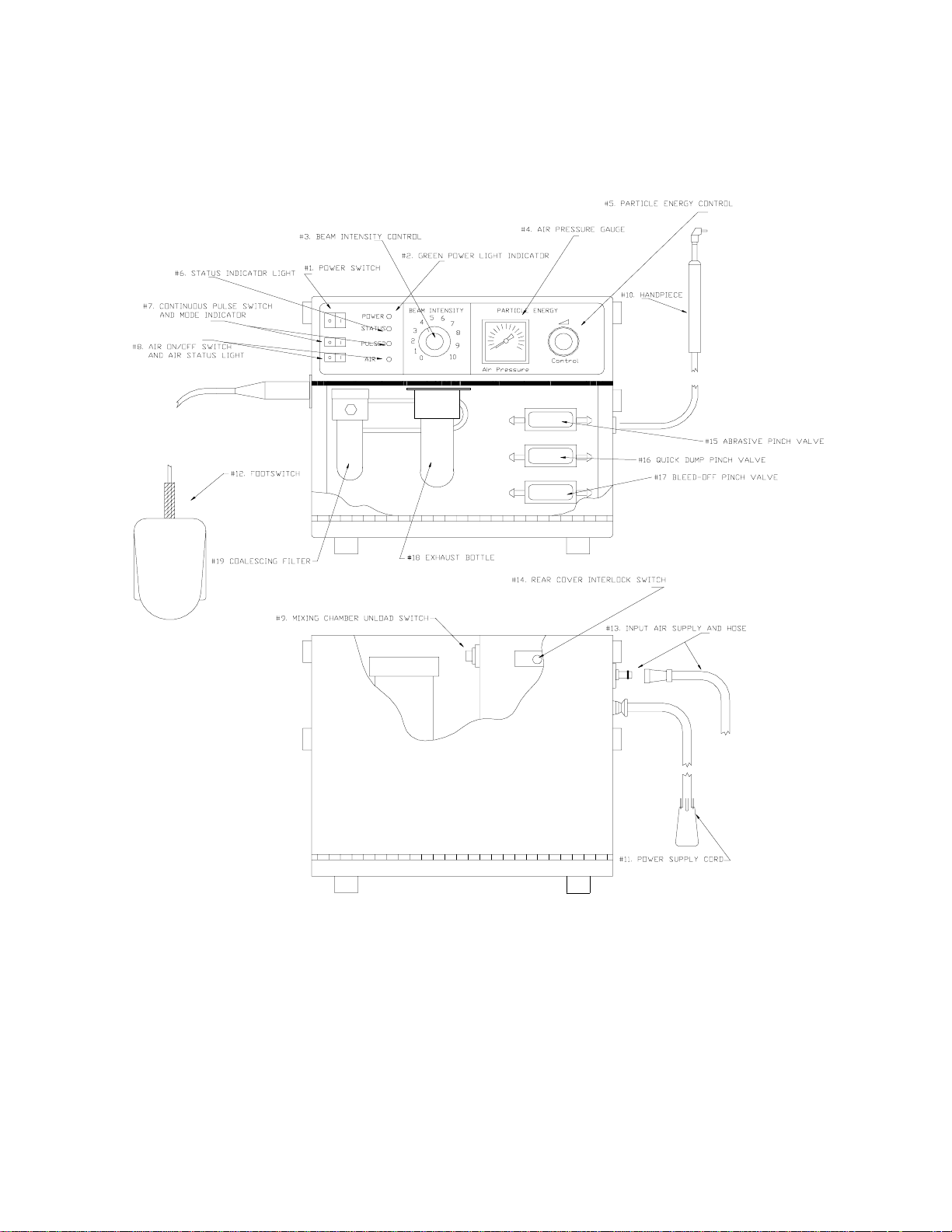
The diagram on page 8 illustrates the external controls, indicators, and connectors for the Kreativ
Models
Names and Functions
#1. Unit POWER Switch;
In the ON position, this switch activates the main power to the unit.
#2 Green POWER Indicator LED
This LED illuminates when the unit POWER switch is in the ON position indicating that
electrical power is ON..
Mach 4.0
and
units. The following describes their functions.
4.1
#3 Beam Intensity Control:
grams/min.)
This knob adjusts the desired rate of powder flow. To operate, begin with minimum abrasive
powder flow and increase until the desired cutting effect is achieved.
#4 Air Pressure Gauge:
Indicates amount of air pressure supplied to the Mixing Chamber and ultimately to the handpiece.
For normal operations, 50-80 psig (345 to 550 kPa) is used. For certain operations a lower or
higher pressure may be desirable.
#5 Particle Energy Control:
Adjusts output air pressure which is indicated on the Air Pressure Gauge.
( Continuously variable from 1-10 (approximately 0 to 7
Page 5 990242 Rev. A
Page 8

#6 Status Indicator LED:
Indicates the status of main (top) pinch valve. When the light is GREEN, the pinch valve is OK.
When the pinch valve tubing ruptures and requires replacing, the Status indicator will flash red
and an audible alarm will sound when the footswitch is depressed.
#7 Continuous/Pulse Switch, Mode Indicator LED:
Select either continuous mode or pulse mode. In continuous mode the indicator LED is AMBER.
In pulse mode the indicator LED is GREEN.
#8 Air ON/OFF switch, Air Status LED:
This switch enables the main air solenoid. When in the OFF (amber) position, the air flow
through the system is disabled. In the ON (green) position the system is pressurized.
#9 Powder Chamber Unload Switch:
This switch enables the vibrator assembly when depressed. When used with the powder chamber
in the unload position causes the abrasive to flow smoothly and easily from the chamber.
#10 Handpiece:
The handpiece holds the nozzle through which the abrasive powder/air flows.
#11 Power Supply Cord:
This power supply cord connects electrical power to the unit. This power requires a properly
grounded outlet.
#12 Footswitch:
The Footswitch is an electric switch. When the foot pedal is depressed the main solenoid is
enabled delivering air/abrasive to the nozzle. The orange protective housing will prevent
accidental activation of the system.
#13 Input Air Supply Hose:
This hose connects the external air supply to the unit. A 1/4-18 NPT fitting is provided on the end
of the hose. The air supply should be from a clean, dry air source.
#14 Rear Cover Interlock Switch:
Disables the air supply when the back cover is opened.
Page 6 990242 Rev. A
Page 9

#15 Main Abrasive Pinch Valve (top)
The top pinch valve opens and closes with depression of the footswitch. It controls the flow of
air/abrasive to the handpiece/nozzle. The Status Indicator LED monitors this pinch valve and will
flash red with a audible alarm when the pinch valve tubing is ruptured and needs replacing.
#16 Quick Dump Pinch Valve (middle)
This pinch valve relieves the pressure and abrasive in the hose and handpiece when the
Footswitch is released. When the footswitch is released the Quick Dump Pinch Valve opens
allowing the built up pressure and abrasive in the hose and handpiece to be expelled into the
Exhaust Bottle.
#17 Bleed Off Pinch Valve (bottom)
This pinch valve is used to depressurize the system when: a) the unit is turned off b) the Air
Switch is in the Off position or c) the Rear Door Interlock is open. In any of the 3 previous
situations the bottom pinch valve will open allowing any pressure in the unit to be released
through the Exhaust Bottle.
#18 Exhaust Bottle
The Exhaust Bottle is used as a relief port for air pressure and abrasive when the footswitch is
released or the unit is turned off or depressurized.. The air and/or abrasive is received via the
middle and/or bottom pinch valve. Any abrasive is filtered and the air is release via a port on the
side of the Exhaust Bottle. Since the Exhaust filters and collects abrasive, it must be periodically
be emptied.
#19 Coalescing Filter
The Coalescing Filter is in the incoming air supply line. It will remove
small
amounts of oil or
moisture that might be in the air supply. It automatically dumps any oil or moisture collected each
time the unit is turned off. If oil or moisture is noticed below the coalescing filter, the air supply
should be checked for the source.
Page 7 990242 Rev. A
Page 10
Page 8 990242 Rev. A
Page 11

Functional Description
The power Indicator LED is illuminated when the unit is ON and ready for use. This
indicates that AC input power is connected to the unit.
Kreativ Models
particles in a dry air stream and delivers this mixture through a nozzle.
The input air supply is routed throughout the system after passing through the main air
solenoid and coalescing filter. One path is through the main regulator (used to set the
desired operating pressure on the control panel) to the mixing chamber where the abrasive
particles are picked up. From there the air carries the particles through the main pinch
valve and on to the handpiece/nozzle when the footswitch is depressed. The second path
is through the pinch valve regulator and pinch valve control system.
The Beam Intensity control regulates the amount of abrasive particles fed into the main air
stream through the mixing chamber.
The air stream combined with abrasive powder is able to cut and etch tooth structure and
ceramic. The abrasive powder/air stream is directed through a light, flexible hose to the
handpiece for precise cutting. Various handpieces are offered with specific orifice (nozzle)
sizes to enable the practitioner to accomplish particular tasks. In addition, a selection of
abrasive powder is available to accommodate all desired uses. Nozzle and abrasive
powder types are listed in Section 9.
When the Power switch is set to
pressure.
Mach 4.0
and
provide a controlled mixture of abrasive powder
4.1
the unit automatically bleeds off the internal air
OFF
Caution
Do not attempt to open the covers of the unit with power turned on!
Page 9 990242 Rev. A
Page 12

4
Unpacking and Setup
General Information
SAVE THE CARTON AFTER UNPACKING THE SYSTEM!
The
Mach 4.0
unpacking, check items against the list of contents packed with the unit.
container and packing materials should be retained in the unlikely event that the unit
has to be returned to the factory for service or repair.
The table on page 11 lists the standard equipment supplied with the unit.
Operation of the
compressed air or nitrogen together with a properly adjusted pressure regulator. In most
cases your standard dental compressor and high volume evacuation system are adequate
for this purpose. For additional information consult your nearest authorized Welch Allyn /
Kreativ service representative.
or
and all accessories are shipped in a single container. When
4.1
Mach 4.0
or
The shipping
requires an external source of either clean, dry,
4.1
Page 10 990242 Rev. A
Page 13

List of Contents
Part Number Item Quantity
Standard Equipment
K01-00090-001 Kreativ
Model Mach 4.0
or
APB with Footswitch 1
4.1
Includes:
130041 Domestic Starter Kit 1
130045 Instructional Video 1
140008 Powder, 27.5 micron (Aluminum Oxide) 4 lbs. ea. 1
170010-2 Green Nozzle, 0.014” (0.36mm) 67° 1
170010-3 Green Nozzle, 0.014” (0.36mm), 90° 1
170011-2 Blue Nozzle, 0.018” (0.46mm), 67° 1
170011-3 Blue Nozzle, 0.018” (0.46mm), 90° 1
170053 Red SST Handpiece/Nozzle Assembly, 45° 1
170081 Footswitch Assembly 1
200002 Standard Handpiece Assembly 2
600105 Domestic Hospital Grade Power Cord 1
990242 Instruction Manual 1
K01-00058-1 Air Supply hose 10' with Quick Disconnect 1
K01-00325-1 Pinch Tube Kit 1
K99-00002-1 Protective Eyewear 3 pr.
K99-00015-1 Fuse, 1A 250V Slo Blo 5 x 20 mm 2
K99-00243-1 Brass Fitting 10-32 x 1/8 for Pneumatic Hose 1
Page 11 990242 Rev. A
Page 14

Unpacking and Setup
Open and remove the
Open the front and rear covers by releasing the latches.
•
Remove the foam packing (3 pieces) used to prevent the vibrator from moving during
•
shipping.
shipped again, the vibrator support foam packing should be reinstalled to
damage
to the vibrator and its mounts.
Failure to remove the foam packing will result in improper vibrator
operation and powder flow.
Supply Requirements
Air Supply:
unit.
A filtered compressed air line or nitrogen may be used as the gas supply for the
or
Mach 4.0
Retain the foam with the shipping box and packing materials.
unit from the shipping container and proceed as follows:
4.1
WARNING
If the unit is to be
prevent possible
The use of compressed oxygen as a gas supply presents a fire hazard.
Under
For optimal use the normal air supply to the unit should be a minimum of 80 psig (550 kPa) with a
maximum of 120 psig (825 kPa), the air source should provide a minimum of 1.5 CFM (42.5 l/m).
Since many dental office compressed air lines may be contaminated with moisture, oil and dirt
which are detrimental to the performance and operation of the unit, moisture filters and unloaders
must be used. Moisture filters for this purpose can be purchased directly from your Welch Allyn /
Kreativ sales representative.
Electrical Requirements
The electrical requirement for this unit is 100-127 VAC, 60 Hz., single phase or 220-240 VAC, 50
Hz. If your requirements are different, consult your nearest authorized Welch Allyn / Kreativ
service representative before operating this unit.
CAUTION!
circumstances should oxygen be used.
NO
Page 12 990242 Rev. A
Page 15

5
Installation and Unit Checkout
After completing the operations in Section 4 you are now ready to begin
installation of your Kreativ
Mach 4.0
Pre-Installation Requirements
1. Adequate Air Supply. Ensure that you have at least 80 PSI (550 kPa) @ 1.5 CFM
(42.5 l/m) of clean, dry air. (The ideal air for the
placing a "T" fitting prior to the final regulator at the operatory but after the dryer, traps
and various filters.)
or
4.1.
Mach 4.0
or
is obtained by
4.1
2. Power supply with earth grounding.
NOTE:
cord.
Unit Checkout
Set the Power Switch on the front panel to OFF, and the POWDER FLOW knob
•
completely counter clockwise to the zero (0) position.
Connect the end of the air supply hose with the quick disconnect to the external air
•
supply.
Plug the power supply cord into a properly grounded receptacle.
•
Set the Power Switch to ON. The green pilot light should be illuminated.
•
Route the power cord safely out of the way and
Page 13 990242 Rev. A
do not use
an extension
Page 16

WARNING!
If the green pilot light does not go on, it indicates absence of electrical power. If,
after verifiying that power is available, the indicator light
consult your local Welch Allyn / Kreativ service representative.
Check the reading on the AIR PRESSURE gauge. Set Particle Energy Control
•
as follows:
1. Pull the black knob out and rotate knob to a reading of 80 PSI (550 kPa) on the
pressure gauge.
2. To prevent any changes push the black knob in/forward to lock it at that setting.
Verify that a Handpiece/Nozzle is attached to the delivery hose.
•
Actuate the Footswitch. Air should flow from the nozzle.
•
STILL
does not go on,
CAUTION!
Some residual powder may be in the unit from factory testing.
use goggles or protective eyewear when using the Kreativ Model
or
4.0
the face when operating the footswitch.
Set the Power Switch to OFF. This allows the system to depressurize.
•
Air Abrasion instrument and do not direct the nozzle toward
4.1
CAUTION!
After turning the Power Switch to the OFF position, monitor the Air
Pressure Gauge to be sure that the air pressure drops to 0. An additional
5 to 10 seconds of depressurizing time must be allowed after the gauge
reading reaches zero (0) before removing the Mixing Chamber Top, or
performing other services.
•
Fill the Powder Chamber as described on the next page.
Always
Mach
Page 14 990242 Rev. A
Page 17

Filling the Mixing Chamber
Observe the following procedures when filling the Mixing Chamber.
Place the Power Switch of the unit to OFF. This allows the system to depressurize.
•
After turning the Power Switch to the OFF position, monitor the Air Pressure Gauge
•
to be sure that the air pressure drops to 0. Allow an additional 5 to 10 seconds after
the gauge reaches 0 before opening the Powder Chamber.
Clean off any dust or debris from the Mixing Chamber top and cover.
•
Remove the Mixing Chamber lid by turning counterclockwise.
•
Carefully pour abrasive powder into the Mixing Chamber until it is 3/4 full.
•
Replace the Chamber lid and tighten.
•
CAUTION!
Make certain that no lint, dirt or other foreign substances enter the chamber.
This can result in plugging the unit.
Operational Checkout
Place the Power Switch to ON and set the Beam Intensity knob to obtain the desired
•
amount of powder flow for the operation to be performed. Powder flow is at a
minimum counterclockwise “zero” position and gradually increases to the clockwise
or “ten” position. Typical dental procedures use powder flow from 3-5 on the dial.
Place the Air Switch to the ON position.
•
Actuate the Footswitch to obtain powder flow through the nozzle.
•
You can now practice operative procedures on extracted teeth as described in Section 2,
Safety.
Page 15 990242 Rev. A
Page 18

Page 16 990242 Rev. A
Page 19

Footswitch Operation
Footswitch operation: depressing the footswitch starts the powder flow through the
•
handpiece/nozzle.
Unit Shutdown
Set the Power Switch to OFF.
•
Unloading Powder Chamber
The illustrations on page 16 show the parts involved in unloading the Mixing Chamber.
Follow these directions when unloading it.
Open the back access panel.
•
Firmly hold the chamber and vibrator and loosen the Mixing Chamber Lid by turning it
•
counterclockwise.
Completely unscrew the lid from the Mixing Chamber.
•
Loosen the locking knob on the Chamber Tilt Plate; slide the Chamber Clamp back to
•
release and tilt the chamber out of the cabinet.
NOTE:
A container must be placed under the chamber opening to catch the abrasive powder.
Set the Beam Intensity on the front panel to “10”.
•
Press the Mixing Chamber Unloading Switch to vibrate the abrasive powder out of the
•
Mixing Chamber.
Tilt the Mixing Chamber back to its upright position.
•
Slide the Chamber Clamp forward over the Chamber Tilt Plate and tighten the knob.
•
Replace the lid and nut making sure the threads are free of powder and the lid gasket
•
is properly seated.
Check the two air hoses attached to the Mixing Chamber to assure that they are not
•
kinked or pinched and that they make a large free loop.
Page 17 990242 Rev. A
Page 20

6
All Kreativ Model Mach 4.0 and 4.1 accessories which come into contact
with the patient
Sterilization Procedures:
Handpiece/Nozzle:
WARNING!
must be sterilized
Sterilization
prior to each use.
Any conventional dental (dry heat, steam or chemical) sterilizer or autoclave may be used to
decontaminate the cutting handpiece/nozzle.
ensures that the handpiece/nozzle cannot become a source for cross contamination of disease or
infection.
Accessories:
The handpiece/nozzle hose assembly of the Kreativ Models
close proximity to the patient or other sources of contamination, should be sheathed or wiped
down in accordance with standard procedures.
Page 18 990242 Rev. A
This is mandatory prior to each use.
Mach 4.0
and
This procedure
which will be in
4.1,
Page 21

7
Operating Instructions
SPECIAL NOTE: As previously stated. you should practice on extracted teeth in order to
appreciate the unique cutting ability of the Kreativ
Intra-Oral Applications:
Cavity preparation for dental restorations.
•
Removal of composite restorations.
•
Partial removal of composite restorations and repair at failure sites.
•
Preparation for pit and fissure sealants.
•
Prophylaxis.
•
Removal of stains from teeth and removal of calculus/tartar from teeth.
•
Prepare teeth for veneer/facing restorations.
•
Etch metal/porcelain/composite restorations prior to repairing them.
•
Prepare teeth for cavity preparations, Class I, II, III, IV & V restorations.
•
Polish metallic restoration margins.
•
Remove old amalgam/porcelain restorations.
•
Remove residual stains from enamel & dentin.
•
Mach 4.0
or
4.1
systems.
Page 19 990242 Rev. A
Page 22

Extra-Oral Applications
Clean cement from a displaced crown prior to recementations.
•
Satinize metallic restoration to locate interference prior to cementation.
•
Etch internal surfaces of restorations.
•
Carve occlusal anatomy in porcelain restorations prior to bonding cementation.
•
Etching stainless steel crown.
•
Satinize restorations to check for seating interference.
•
Clean restorations prior to recementation.
•
CAUTION!
DO NOT USE the Kreativ Model
Mach 4.0
or
for procedures not included or
4.1
suggested in this instruction guide.
The Kreativ Model
Mach 4.0
and
systems should be used
4.1
only
by dental
professionals who have practiced on extracted teeth and who are thoroughly familiar
with this manual.
The use of the Kreativ Model
⇒
Mach 4.0
and
systems as described can generally be well tolerated
4.1
by patients without local anesthesia. If a patient reports discomfort, an anesthetic may be called for.
In general, cutting speed increases with:
⇒
⇒
⇒ ⇒
increased air pressure,
•
increased powder flow,
•
and decreased distance to the tooth structure.
•
Cutting speed decreases with:
⇒
decreased air pressure
•
decreased powder flow
•
and increased distance to the tooth.
•
Page 20 990242 Rev. A
Page 23

Enamel cuts slower than dentin thus:
⇒
It may take
•
But it may take
•
Increased powder flow and air pressure will increase cutting speed, but it will also deliver more
⇒
powder which must be controlled with the high volume evacuation.
Most preparation procedures can be easily accomplished with:
⇒
•
Start by using the general settings (above) and the 0.018 (0.46 mm) tip.
⇒
As you gain experience choose the nozzle size and system settings which suit your individual needs.
⇒
•
With experience you will find a comfortable balance between
cutting speed and controlling the powder flow in the mouth.
about 60-80 PSI (619-825 kPa)
the powder flow set at about 3-5.
1-2 minutes
only 5 seconds
to complete a class I preparation on a molar
to complete a class V preparation on a premolar.
General Operating Procedures
The Cutting Process:
The unit performs a cutting action by impinging sharp-edged powder particles onto a surface. A
cylindrical powder/air stream emerges from the nozzle for a short distance (approximately 1.6
mm) and then diverges into a cone shape, with a seven degree included angle. Within the 1.6 mm,
the nozzle makes small holes and straight walled cuts. As one moves the nozzle away from the
work, the hole diameter or width of cut increases, and the walls become angular. The angle can be
determined with a few trials. To obtain sharp definition (as in precise cutting) use the 0.014
(0.36mm) diameter nozzle and keep the nozzle tip to a minimum of 0.8 mm from the work.
Cutting Speed:
The cutting speed (removal of material) increases up to a certain nozzle distance.
Vary the cutting rate by:
1) adjusting the powder flow and/or air flow.
2) using different pressure settings .
3) using different powder sizes.
4) using special type nozzles.
Etch or remove broad areas of metallic film or coatings by increasing the nozzle tip distance and
diverting the air stream at an acute angle.
″
Page 21 990242 Rev. A
Page 24

Powder Flow Adjustment
Depressing the footswitch causes a mixture of powder and air to be discharged from the nozzle.
Control the mixture richness with the Beam Intensity Knob which adjusts the vibrator speed. We
suggest starting between the 3 and 5 position.
Pressure Behind the Nozzle
Necessary air pressure varies depending upon:
the material being cut.
•
the type of cut.
•
the abrading process desired.
•
the powder being used..
•
We suggest starting at 65 PSI (447 kPa).
Check the Progress of the Cavity Preparation
Stop frequently,(every few seconds) and make a visual inspection of the progress
As you begin using the Kreativ Model
of air/powder mixture.
DO NOT continue for more than 5 seconds without stopping to make a visual
•
inspection.
For class V restorations DO NOT continue for more than
•
to examine the results.
Mach 4.0
or
, we suggested that you use short bursts
4.1
2 seconds
.
without stopping
Use a Saliva Ejector
As with any other cavity preparation procedure, your conventional saliva ejector should be
normally positioned in the patient’s mouth to collect the saliva and rinse water.
Use Your High Volume Evacuation System
This is important when using the Kreativ Model
procedures. Place the HVE about ! to 1 cm from the operative site to collect the abrasive powder.
Mach 4.0
or
for cavity preparation or cutting
4.1
Page 22 990242 Rev. A
Page 25

Stopping to Rinse
Most cavity preparations will take between 30 seconds to 1½ minutes. On longer procedures some
patients will experience discomfort from dryness and may wish to have their mouth rinsed with
the water syringe and evacuated with the saliva ejector.
WARNING!
Without adequate filtration, use of the
the metal parts of your vacuum system.
Step-by-Step Operating Instructions
Notes:
Proceed as follows:
1. Remove the Handpiece/Nozzle from its sterile package and place it on the Air Supply Hose.
2. Prepare your patient just as you would for traditional procedures.
A ) Always pre-load the Mixing Chamber with the abrasive powder appropriate for the
procedure to be performed.
B ) Make sure that the
air source
C ) Make sure the power cord is connected to a properly grounded receptacle.
Mach
4.0
or
4.1
may accelerate the wear on
is connected to the input
air supply hose
.
3. Turn the Kreativ Model
Mach 4.0
or
unit Power Switch to ON.
4.1
(The green light should be illuminated.)
4. Turn the Air Switch to the ON position.
5. Adjust the air pressure and powder flow to the rates needed for the procedure.
6. With the nozzle pointed into a receptacle such as a sink or your vacuum system, press the
footswitch to check that the air-powder mixture is flowing from the nozzle.
7. Direct the tip at the desired target tissue, and with the aspirator in place, begin the procedure.
Observe the progress carefully!
Page 23 990242 Rev. A
Page 26

8. When the procedure has been completed, turn the Power Switch to OFF. The Main Air Valve
will be closed, the input air supply will shut off, the unit will depressurize.
CAUTION!
When changing powders, you must discharge any residual powder
remaining in the air lines. To do this, depress the footswitch; it will take
several seconds to discharge the previous powder from the system
Page 24 990242 Rev. A
Page 27

8
Troubleshooting and Maintenance
PROBLEM PROBABLE CAUSE REMEDY
No power
No powder flow when
footswitch is depressed
Air flow from nozzle when
footswitch is not depressed
Erratic powder flow
Instrument not plugged in
•
Main switch OFF
•
•
•
Blown Fuse
• •
•
•
Main switch bad
• •
Footswitch not plugged in
•
Powder flow not selected
•
Handpiece/nozzle clogged
•
Tubing pinched
•
Air Valve problem
•
•
•
Mixing Chamber empty
• •
•
•
Loss of air pressure due to an
• •
improperly adjusted Air
Valve regulator
Powder caking in Chamber
•
Chamber empty
•
Nozzle partially clogged
•
Vibrator inoperative
•
Moisture in air line
•
Check plug
Check switch
Change fuse
Call Service Representative
Check connection
Check gauge
Check for clog
Check tubing
Call Service. Rep.
Refill Mixing Chamber with
abrasive powder
Call Service Representative
Replace powder
Check powder level
Check nozzle
Call Service Representative
Check filters
Page 25 990242 Rev. A
Page 28

PROBLEM PROBABLE CAUSE REMEDY
No powder flow
Powder spray loses definition
Status LED flashes red with
audible alarm
Periodic Service
The Kreativ Models MACH 4.0 and 4.1 should be inspected periodically for:
Damaged Mixing Chamber Cover, Cap, Cap Nut and cover seal on Chamber
•
Worn or damaged hoses.
•
Clogged orifice in Chamber Disassemble & clean
•
chamber
Worn nozzle tip
•
Too much distance
•
Indicates main (top) pinch
•
valve is ruptured
Replace nozzle
Move closer
Replace pinch valve tubing
Loose wire or hose connections.
•
Burned out indicator lamp.
•
Proper Operation of controls and gauges.
•
Worn nozzle or handpiece.
•
The unit should be periodically cleaned, as follows:
Clean dust and spilled powder from the unit
•
air or vacuum from the dust collector.
Remove stubborn dirt with a brush.
•
DO NOT USE FLUID
•
Clean the external surfaces of the unit with a cloth moistened with a mild cleaning
•
solution such as Windex or rubbing alcohol.
on the hoses or wire insulation.
Page 26 990242 Rev. A
interior
using low pressure compressed
Page 29

Handpiece/Nozzle Tips
The nozzle tips are made of tungsten carbide or sapphire which crack easily, so they
•
must be handled and stored with care.
Nozzle tips sometimes wear, enlarging the side wall. An air stream with lack of
•
definition signals that the nozzle is worn and the tip should be replaced. To do this
unscrew the nozzle from the handpiece and screw in a new one. Make certain that the
new nozzle is fastened securely to avoid powder leaks. Avoid cross threading.
The Red, Violet and Gold SST handpiece/nozzle assemblies do not come apart.
•
Replace a handpiece by disconnecting it from the air hose and replacing it with a new
•
one.
On occasion the nozzle of the handpiece will clog due to excessive flow of powder.
Unclog the nozzle as follows:
1) Remove the handpiece from the air hose and turn the Beam Intensity control knob completely
counterclockwise.
2) Hold the tip end of the nozzle tight against the air hose connector.
3) Turn the unit on end and actuate the Footswitch, supplying air to reverse flush the clogged tip.
NOTE:
This should be done in an exhaust chamber.
Handpiece/nozzles for special applications are available. Consult your Welch Allyn / Kreativ
sales representative for information.
Pinch Valve Tube Replacement:
The rubber pinch valve tube wears and will eventually leak.
NOTE:
The Pinch Valve body does NOT have to be removed from the unit for tube replacement.
Page 27 990242 Rev. A
Page 30

1) Set the Power Switch to the OFF position and monitor the Air Pressure Gauge to be sure that
the air pressure drops to 0. Allow an additional 5 to 10 seconds after the gauge reading
reaches 0.
2) Remove the front black block from the assembly by removing the two knurled screws.
3) Remove the tube from the fittings and carefully insert the new control valve tube between the
fittings.
4) Insert the new pinch tube and fittings into the bottom block indentation.
NOTE:
Be sure to align the pinch valve’s seam to the side of the block.
5) Carefully replace the front cover. Again making certain that the tube aligns with the
indentations in the top block. Secure the front cover in place with knurled screws, making
sure that the thumb screws are tightened down finger tight.
6) Turn the Power Switch to ON and check for proper operation and leaks.
Air ON/OFF Valve
The Air ON/OFF valve controls the flow of air into the unit. The valve is either open, providing
air flow, or closed, stopping the flow. The valve is not field repairable. Your nearest Welch
Allyn / Kreativ service representative will replace it if it malfunctions.
Air Pressure Gauge. The air pressure gauge is not field repairable and should be replaced with a
new one if it malfunctions or fails to operate.
Exhaust Bottle
The Exhaust Bottles in the
Mach 4.0
and
collect small amounts of powder each time the
4.1
footswitch is released or the system is turned off. Check the amount of powder collected in the
Exhaust Bottle every time you refill the canister with powder. It needs to be emptied when it is
approximately half full.
Page 28 990242 Rev. A
Page 31

9
Handpieces
These custom nozzles are available for the Kreativ Mach 4.0 and 4.1:
Handpieces and Abrasives
0.011” (.28mm) ID at either 45°, 67° or 90°
•
0.014” (.36mm) ID at either 45°, 67° or 90°
•
0.018” (.46mm) ID at either 45°, 67° or 90°
•
0.026” (.66mm) ID at 45° only
•
Supersonic handpiece / nozzle assemblies available for the Mach 4.0 and 4.1:
Abrasives
0.032” (.88mm) ID at 45° only
•
0.11” (0.28mm) ID Violet at 45°, 67° or 90°
•
0.14” (0.36mm) ID Gold at 45°, 67° or 90°
•
0.18” (0.46mm) ID Red at 45°, 67° or 90°
•
27.5 Micron Aluminum Oxide
•
27 Micron Aluminum Oxide
•
34 Micron Aluminum Oxide
•
50 Micron Aluminum Oxide
•
Page 29 990242 Rev. A
Page 32

10
Returns and Adjustments
Warranty claims must be made promptly and received by your nearest authorized Welch
Allyn / Kreativ service representative during the warranty period. The liability of Kreativ
Inc., under valid warranty claims, is limited to repair or replacement at the purchaser’s
authorized Welch Allyn / Kreativ Service Center or the purchaser’s place of business, at
the option of the authorized service representative. If it is necessary to return a product for
repair or replacement, authorization for the return must first be obtained from the
authorized service representative.
Warranty, Returns and Adjustments
All products returned for examination or warranty repair must be sent insured via a means
of transportation specified by your authorized Welch Allyn / Kreativ service
representative.
Kreativ, Inc., or its authorized service representative claims the sole responsibility for
determining the cause of any instrument failure.
Limited Warranty
Kreativ Inc. warrants the equipment to be free from defects in material and workmanship
for a period of 12 months from the date of shipment. Damage due to failure of customer
to perform required user/preventive maintenance is not warranteed. Certain components
having limited life expectancy (pinch tubes, air/abrasive tubing, handpieces and
Page 30 990242 Rev. A
Page 33

handpiece tips) are not warranteed against normal wear and tear or customer damage.
This limited warranty applies only to the original purchaser / user of the equipment.
The foregoing limited warranty is exclusive and in lieu of all other warranties, whether
written, oral, or implied, and shall be purchaser’s sole remedy and Kreativ’s sole liability
under contract or warranty or otherwise for the product.
Kreativ, Inc., disclaims any implied warranty of merchantability or fitness for particular
purposes. In no event shall Kreativ, Inc. be liable for any incidental or consequential
damages, or for any incidental or consequential damages arising out of, or in connection
with, the use or performance of the product delivered hereunder.
Storage And Shipment
The Kreativ Models
Mach 4.0
and
have been designed for long term storage in
4.1
normal dental office environments. If it is to be stored for any reason for a long period, it
should be covered to protect it from elements and the Mixing Chamber should be emptied.
The area it is to be stored in should meet the Environmental Limitations indicated in the
Specifications section of Chapter 1.
The unit has been designed for shipment by normal commercial carriers. Protective
packaging should be used, and the original packing materials should be reinstalled for
shipment. Shipping instructions must be followed closely. The purchaser will be
responsible for damage resulting from improper packing.
Page 31 990242 Rev. A
 Loading...