

Page 1

KOMPRESSOR
Kreativ Menu
Manuals
Operator Manual
SERVICE MANUAL
Copyright Notice:
Copyright © 1999, Kreativ, Inc. All rights reserved. No part of this manual may be
reproduced without written permission from Kreativ, Inc.
Manufactured by
Welch Allyn Kreativ, Inc. (USA)
7360 Carroll Road
San Diego, CA 92121
990276 Rev. A
European Authorized Representative
Welch Allyn LTD.
Navan, Co. Meath
Republic of Ireland
Ph: 353-46-79060
Page 2

TABLE OF CONTENTS
1. GENERAL INFORMATION......................................................................................................................................................4
1.1 INTRODUCTION.......................................................................................................................................................................4
1.2 PURPOSE OF MANUAL...........................................................................................................................................................4
1.3 SAFETY SUMMARY................................................................................................................................................................4
1.4 APPLICATIONS........................................................................................................................................................................5
1.5 CONTRAINDICATIONS............................................................................................................................................................6
1.6 E NVIRONMENTAL CONSIDERATIONS..................................................................................................................................6
1.7 SYSTEM SPECIFICATIONS .....................................................................................................................................................6
2. THEORY OF OPERATION.......................................................................................................................................................7
2.1 INTRODUCTION.......................................................................................................................................................................7
2.2 FUNCTIONAL DESCRIPTION.................................................................................................................................................7
2.3 COMPONENT IDENTIFICATION............................................................................................................................................8
3. ROUTINE MAINTENANCE .....................................................................................................................................................13
3.1 ROUTINE MAINTENANCE OF THE KOMPRESSOR ..........................................................................................................13
3.2 MONTHLY REQUIREMENTS................................................................................................................................................13
3.3 ANNUAL REQUIREMENTS...................................................................................................................................................16
3.4 2 Y EAR REQUIREMENTS......................................................................................................................................................21
4. TROUBLESHOOTING............................................................................................................................................................23
4.1 TROUBLESHOOTING CHART ...............................................................................................................................................23
5. SPARE PARTS LIST...............................................................................................................................................................24
5.1 TUBING...................................................................................................................................................................................24
5.2 FILTERS/MECHANICAL/PNEUMATIC COMPONENTS......................................................................................................24
5.3 FITTINGS ...............................................................................................................................................................................24
5.4 ACCESSORIES AND OTHERS.................................................................................................................................................24
5.5 ADHESIVES.............................................................................................................................................................................25
5.6 CHASSIS COMPONENTS........................................................................................................................................................25
5.7 MAINTENANCE KITS...........................................................................................................................................................25
6. WARRANTY, RETURNS AND ADJUSTMENTS...............................................................................................................26
6.1 RETURNS AND ADJUSTMENTS...........................................................................................................................................26
6.2 L IMITED WARRANTY..........................................................................................................................................................26
6.3 STORAGE AND SHIPMENT ..................................................................................................................................................26
990204 Rev. A Page 2 of 25
Page 3

TABLE OF FIGURES
FIGURE 1 SYSTEM.............................................................................................................................................................................7
FIGURE 2 KOMPRESSOR COMPONENTS.......................................................................................................................................10
FIGURE 3 KOMPRESSOR COMPONENTS.......................................................................................................................................10
FIGURE 4 KOMPRESSOR COMPONENTS.......................................................................................................................................11
FIGURE 5 KOMPRESSOR PNEUMATIC BLOCK DIAGRAM..........................................................................................................11
FIGURE 6 OIL SITE G LASS..............................................................................................................................................................12
FIGURE 7 OIL FILL HEX PLUG.......................................................................................................................................................13
FIGURE 8 JUN AIR MUFFLER.........................................................................................................................................................14
FIGURE 9 MANUAL DRAINS...........................................................................................................................................................14
FIGURE 10 FILTER LOCATIONS.....................................................................................................................................................15
FIGURE 11 OIL COLLECTION BOTTLE........................................................................................................................................15
FIGURE 12 KOMPRESSOR TOP REMOVAL....................................................................................................................................16
FIGURE 13 FILTER ASSEMBLY REMOVAL...................................................................................................................................17
FIGURE 14 OIL COLLECTION BOTTLE........................................................................................................................................17
FIGURE 15 OIL COLLECTION BOTTLE BOWL AND “O” RING ................................................................................................17
FIGURE 16 OIL COLLECTION BOTTLE COMPONENTS.............................................................................................................18
TABLE 1 MAINTENANCE CHECKS................................................................................................................................................19
990276 Rev. A Page 3 of 25
Page 4

1. General Information
1.1 Introduction
The Welch Allyn Kreativ Kompressor is a compact, highly reliable, state of the art instrument designed for use with
Welch Allyn KREATIV Air Abrasion systems. It is designed as a stand alone means of supplying clean dry air for
use by these systems.
Note: Use of the Kompressor system in a set up that is not included or suggested in this instruction guide is not
advised. Similarly, the Kompressor system should be only used by someone who is thoroughly familiar with this
manual.
1.2 Purpose of Manual
This manual should be thoroughly studied before installing, using, or performing maintenance on the equipment.
Please feel free to call Welch Allyn Kreativ or their representative if you need additional information regarding
installation, operation, or service of the instrument.
Information essential to the installation, operation, and routine maintenance of the Kompressor system manufactured
by Welch Allyn Kreativ, is included in this manual. The instructions are written specifically for personnel who have
been trained to perform maintenance on the unit.
1.3 Safety Summary
1.3.1 Read This Manual
Prior to operating or servicing the Kompressor, this manual must be read and understood. If something is not clear,
call the factory for assistance before proceeding. Keep this and other associated manuals for future reference.
1.3.2 Use Proper Power Connections
Use proper wiring and connection methods to satisfy appropriate electrical codes.
1.3.3 Do Not Remove Covers Or Panels
To avoid electrical shock hazard, do not remove covers or panels when power is supplied to the unit. Do not operate
the device when the covers or panels are removed.
1.3.4 Shock Hazard
Connect the Kompressor to a properly grounded outlet in accordance with the National Electrical Code.
WARNING: Do not under any circumstance remove the ground wire or the ground prong from any power plug. Do
not use extension cords with the Kompressor equipment.
1.3.5 Device Labeling
990276 Rev. A Page 4 of 25
Page 5
Do not under any circumstances remove any CAUTION, WARNING, or other descriptive labels from the device.
1.3.6 Other Safety Statements
Other safety statements are included within the manual text and are identified as follows:
• CAUTION: Caution statements identify conditions or practices that could result in equipment or
property damage.
• WARNING: Warning statements identify conditions or practices that could result in personal injury or
loss of life.
1.3.7 Cautions
Do not attempt to service the unit beyond those items described in the maintenance section. Call Welch Allyn
Kreativ or their representative for instructions.
Do not substitute non-Welch Allyn Kreativ , materials or accessories. Use of materials or accessories supplied by
other manufacturers may result in damage to the unit and will void the factory warranty.
Sound clinical judgment, good common sense, and proper training are essential to the successful service of the unit
in order to provide safe and efficient patient care.
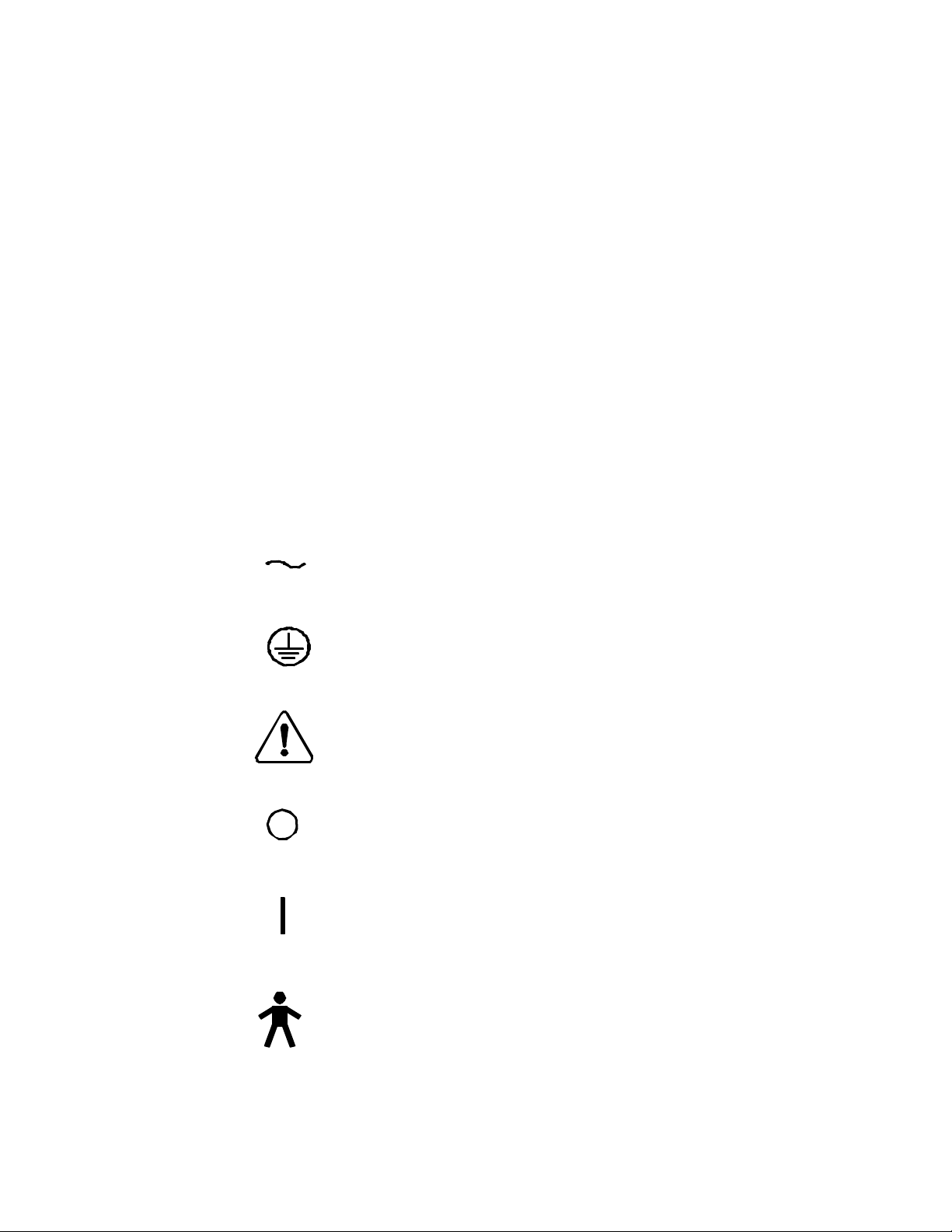
1.3.8 Safety Markings on Labels
Alternating current
Protective earth (ground)
Attention, consult accompanying documents
Off (power: disconnection from the mains)
On (power: connected to the mains)
Type B equipment
1.4 Applications
990276 Rev. A Page 5 of 25
Page 6

The Kompressor is designed for simple, reliable, and efficient operation with minimal maintenance. The Welch Allyn
Kreativ Kompressor system is designed to deliver continuous air pressure and flow.
1.5 Contraindications
Welch Allyn Kreativ products are designed for use by and on the order of a dentist. Furthermore, Welch Allyn
Kreativ products are not intended to be used outside the device’s specifications or limitations. Results are not
guaranteed or warranted if other than approved (Welch Allyn Kreativ) disposable products are used.
1.6 Environmental Considerations
Prior to the installation of the Kompressor air abrasion unit, it will be necessary to provide utilities and create an
environment suitable for the trouble-free operation of the equipment.
1.6.1 POWER
All components operate on 120 VAC (220 VAC International), single phase power. The use of surge protectors is
recommended when possible.
1.7 System Specifications
Size 16” W x 23” H x 20.5” D
(6.3 cm W x 9 cm H x 8 cm D)
Weight 75 lbs. (34 kg)
Environment
Operational Temp: 50°F (+10°C) to 104°F (+40°C)
Relative humidity: 30% to 75%
Pressure: 10.15 psi (70 kPa) to 15.3 psi (106 kPa)
Transport and
Storage
Equipment
Classification
Temp: -40°F (-40°C) to 158°F (+70°C)
Relative humidity: 10 % to 90 %
Pressure: 7.25 psi (50 kPa) to 15.3 psi (106 kPa)
Class I (requires an electrical earth ground) and
ordinary protection against ingress of water. This
unit is designed for continuous operation.
990276 Rev. A Page 6 of 25
Page 7
2. Theory of Operation
2.1 Introduction
The Kompressor is made for use with a Welch Allyn Kreativ air abrasion system.
Mach - 6 Unit
mounted
Compressor
Assembly
Figure - 1 Compressor Assembly with mounted Mach-6
2.2 Functional Description
When the unit is initially turned on, the fan energizes and the compressor will turn on allow the accumulator tanks to
pressurize. Once 160 PSI is reached, the compressor motor turns off by action of the mechanical/electrical pressure
switch and motor start relay. Upon turning off of the compressor motor, the head pressure release valve dumps the
head pressure into the oil collection bottle. As air is drained from the accumulator tanks, when the pressure in the
lower tank reaches 125 PSI, the compressor motor turns on, at the same time, the Tank Purge valve opens, for
990276 Rev. A Page 7 of 25
Page 8

approximately 1 second, and purges the oil/water in the bottom of the air tank then closes and the compressor turns
on.
2.3 Component Identification (refer to Figure - 2, 3, and 4)
2.3.1 Compressor Motor
The compressor motor is an oil bath version capable of delivering 1.2 CFM @ 120 psi. The motor can be rated at 120
VAC or 240 VAC.
2.3.2 Air Input Muffler
The air input Muffler keeps dirt out of the internal oil bath. The motor is shipped with a cap in this location to avoid
oil spillage during transportation. It must be removed and replaced with the filter before applying power.
2.3.3 Starter Capacitor
The starter capacitor comes with the motor and is located under the electrical box.
2.3.4 Mechanical/Electrical Pressure Switch & Motor Start Relay
The pressure switch module is mounted to the lower air tank, and has a plastic cover with an Off / Auto switch
located on top. Leave this switch in the Auto position. An mechanical/electrical pressure switch starts the motor
when the pressure drops to 125 PSI and stops the motor when the pressure reaches 160 PSI. It also opens the tank
purge valve (for a second or two) each time the motor starts, and opens the head pressure release valve each time the
motor shuts off. The motor On/Off set point is adjusted by screws under the plastic cap.
2.3.5 Head Pressure Release Valve (Unloader valve)
The head pressure release valve opens each time the motor shuts off, and dumps the pressurized air/oil from the
motor head into the oil collection bottle. This makes it easier for the motor to start. It is mounted underneath the
mechanical/electrical pressure switch assembly.
2.3.6 Tank Purge Valve
The tank purge valve, located next to the air shut off valve, opens for one second each time the motor turns on. This
valve purges the oil/water that collects at the bottom of the air tank into the oil collection reservoir.
2.3.7 Upper Air Tank
The upper air tank is a 1.5 liter tank mounted horizontally above the compressor motor.
2.3.8 Check Valve
The check valve allows air flow into the upper air tank, but not out of.
2.3.9 Blow Off Valve
The blow off valve, a spring loaded safety release valve (set @ 175 ± 7 psi) is attached to the bottom of the upper air
tank.
2.3.10 Lower Air Tank
The lower air tank, 1.5 liter tank mounted vertically, is located next to the compressor motor. The pressure switch
assembly, shut off valve, pressure gauge, and tank purge valve are in the lower air tank.
2.3.11 Pressure Gauge
The pressure gauge, mounted on the lower air tank, indicates tank pressure. Used to monitor motor turn on and off
pressures as set by the pressure switch. For quick reference only.
990276 Rev. A Page 8 of 25
Page 9

2.3.12 Air Shut Off Valve
The air shut off valve isolates the system regulator and filter bank from the tanks. This valve is a multi-turn gate
valve. It is located on the lower air tank assembly. It should be fully open under normal conditions.
2.3.13 System Regulator
The system regulator, attached to the filter bank, is adjusted to 130 psi and supplies this pressure to the outside
connector.
2.3.14 Oil Removal Filter
The oil removal filter, next to the system regulator, removes 99.9% of oil and moisture. The filter has a manual drain
on the bottom of the filter. If moisture or oil is noticed, pushing the drain will allow the moisture or oil to drain into the
oil collection reservoir.
2.3.15 Odor Removal Filter
The odor removal filter, next to the oil removal filter, has an active carbon element. It has a filtration level of 0.01um
(95% scavenging particle size).
2.3.16 Ambient Dryer
The ambient dryer, next to the odor removal filter, is designed to remove all water vapor from the air when at ambient
temperature.
2.3.17 Oil Collection Reservoir
The oil collection reservoir, is located in the unit back near the bottom. The filter element traps all oil and moisture
while allowing air to escape. Used as a collection reservoir for tank purge and head pressure release valves, and for
the oil filter flushing process. The user must monitor and empty this filter before the bottle becomes full or overflows.
2.3.18 Circuit Breaker On/Off Switch
The On/Off switch, is also a circuit breaker. It is on the back lower panel. Internal connections are protected by a
safety shield. The circuit breaker is rated at 12 Amps in the 120 volts AC and 6 Amps in the 240 volt AC systems.
2.3.19 AC Terminal Block
The AC terminal block is located under the safety shield and is used to distribute power to the compressor motor, the
cooling fan, and the auxiliary power supply cable.
2.3.20 AC Cooling Fan Motor
The AC Cooling fan is energized when the On/Off switch is on. It is aimed at the upper air tank to help cool the
system, and the air heated by the compressor motor.
990276 Rev. A Page 9 of 25
2.1.13 System
Regulator
2.1.14 Oil
Removal Filter
2.1.15 Odor
Removal Filter
2.1.16 Ambient
Dryer
Page 10

2.3.7 Upper
reservoir
Pressure Switch
Motor
Air Tank
2.3.20 AC Fan
2.3.2 Air Inlet
Muffler
2.3.4 Mech/Elect
2.3.5 Unloader
Valve (Figure -
X)
2.3.6 Tank Purge
Valve
2.3.10 Lower
Air Tank.
2.3.11 Pressure
Gauge
2.3.1 Compressor
Motor
2.3.3 Starter
Capacitor
2.3.19 AC
Terminal Block
Figure - 2 Kompressor components
2.3.18 Circuit
Breaker On/Off
Switch
2.3.17 Oil
Collection
2.3.16 Ambient
Dryer
Air Abrasion
Unit External
Power Supply
2.3.9 Blow Off
Valve
2.3.8 Check
Valve
Figure - 3 Kompressor components.
990276 Rev. A Page 10 of 25
Page 11

2.3.12 Air Shut
Off Valve
2.3.5 Unloader
Valve (K350005)
Figure - 4 Kompressor components
Compressor System Block Diagram
Input
filter
AC Voltage
In
Air
Air Output
Circuit
Breaker
On/Off
Switch
Compressor Motor
Starter
Capacitor
Atmosphere
Ambient
Dryer
Oil Collection
Bottle
Terminal
Block
motor
electrical
box
AC
Odor
Removal
Filter
Oil
Removal
Filter
AC Fan
Motor
Mechanical /
Electrical Pressure
Switch & Motor Start
Head pressure
release valve
Check
Valve
Relay
System
Regulator
31
Upper Air Tank
Atmosphere
Blow off
Valve
2
Tank purge
valve
31
Pressure
Gauge
Air shut
off valve
Legend
Lower Air Tank
Air Path
Electrical Connection
Figure - 5 Kompressor Block diagram
990276 Rev. A Page 11 of 25
Page 12

3. ROUTINE MAINTENANCE
3.1 Routine Maintenance of the Kompressor
Welch Allyn Kreativ Kompressor system has been designed to operate with a minimum of operator attention. Like all
mechanical systems, they will operate longer and with less trouble when operator maintenance is performed regularly.
Maintenance on a Welch Allyn Kreativ Kompressor system is limited to visual inspection, cleaning, and filter
cartridge replacement. The maintenance procedures have been categorized by their frequency of action and are
described in this chapter with specific instructions.
3.2 Monthly Requirements
3.2.1 Check Oil Level
The Kompressor is equipped with an internal air compressor. The air compressor does not require any general
maintenance except adding oil. The compressor is equipped with a oil site glass or viewing window that has a
minimum/maximum indicator line to help the user identify when oil is required.
Figure - 6 Oil Site Glass
990276 Rev. A Page 12 of 25
Page 13

To add oil perform the following:
HEX Fill Plug
Figure - 7 Kompressor Hex Plug
1. Ensure that the unit’s power is in the OFF position, and remove the power cord from the electrical
outlet.
2. Open the right side door.
3. With a crescent wrench, remove the top hex plug (figure - 7), located on the top center of the
compressor head, by turning counterclockwise.
4. The Kompressor is shipped with extra oil (K99-00116-1) and tubing for future use.
NOTE: Use factory-specified oil only.
5. Cut a small portion of the oil container nipple. Slide the tubing onto the oil container nipple.
6. Set the open end of the hose into the hole where the hex plug was removed.
7. Gently squeeze the container of oil, pour a small amount and then stop and let the oil level settle before
adding more.
NOTE: Following step 7 will prevent overfilling the Kompressor and ultimately the oil collection
bottle.
8. Repeat step 7 until the oil level settles just below the maximum line. Discontinue adding the oil by
removing the tubing.
9. Replace the hex plug, and ensure that it is tight.
990276 Rev. A Page 13 of 25
Page 14

Filter drain
Ambient dryer
drain
3.2.2 Intake Muffler
The Kompressor is equipped with an intake muffler/filter. This muffler should be checked every month for
cleanliness. The muffler looks like that in figure - 8.
Intake Port -
Inspect for cleanliness
(K370007)
Figure - 8 Jun Air Muffler
3.2.3 Check and Drain Oil Removal Filter and Ambient dryer
Every month the Ambient dryer should be checked for moisture.
Every month the Oil Removal filter should have the manual drain exercised to remove any oil or moisture that may
have accumulated in it (refer to Figure - 9).
Every month the Odor Removal filter should be inspected for moisture.
If excess oil and/or condensation are found, the Kompressor should be assessed and repair performed as needed.
Odor Removal
filter
Oil Removal
Figure - 9 Manual Drain fittings
990276 Rev. A Page 14 of 25
Page 15

3.3 Annual Requirements
3.3.1 Filter replacements
There are 5 filter assemblies that should be changed once a year at a minimum.
Oil Collection Bottle filter replacement 1 each (K480105)
Ambient Dryer Filter replacement 1 each (K480100)
Odor Removal Filter Assembly 1 each (K480007)
Oil Removal Filter replacement 1 each (K480099)
Air Intake Muffler replacement 1 each (K370007)
Oil Removal Filter
replacement (K480099)
Odor Removal filter
replacement assembly
(K480007)
Ambient Dryer
replacement filter
(K480100)
Figure - 10 Filter locations
Figure - 11 Oil Collection bottle
Air Intake Muffler
replacement assembly
(K370007)
Oil Collection Bottle
filter/O ring
replacement (K480105
and K370026)
990276 Rev. A Page 15 of 25
Page 16

3.3.2 Oil Removal, Odor Removal, and Ambient Dryer filter replacement
To replace these 3 filters, follow the following instructions.
1. Verify the system has no leaks before maintenance is performed. To do this perform the following steps:
a. Energize the system and allow pressure to build.
b. After Kompressor has stopped, the gage on the unit should maintain pressure without
decreasing.
c. If the pressure decreases, repair leak prior to performing maintenance.
1. Disconnect AC power.
2. Unlatch and remove the left and right side panels using the hex key provided in the accessory kit.
3. Depressurize the system by pressing the manual valve on the bottom of the Oil Removal Filter.
4. When the pressure has bled off, disconnect and remove the Mach 6 unit from the top of the
Kompressor.
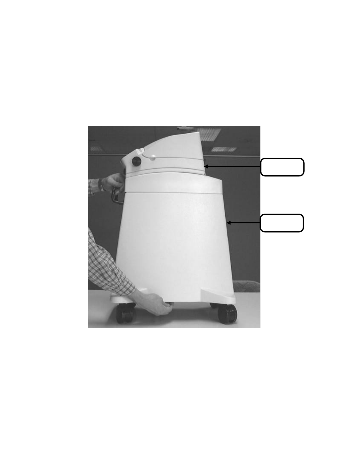
5. Remove the 4 phillips screws holding the top of the Kompressor to the frame (refer to figure - 12).
6. Remove the top and set aside for re-assembly.
7. Disconnect the tubing going into the System regulator, the drain out of the Oil Removal filter, and the
out put of the Filter Assembly (refer to Figure - 13).
8. Remove the two phillips screws holding the filter assembly to the frame (refer to Figure - 13).
9. Remove the Filter Assembly.
NOTE: After removal of Filter assembly components, all joints should be resealed with
Pneumatic Sealant.
10. Disassemble and replace the Ambient Dryer Filter Element. Set aside for re-assembly.
11. Remove and discard the Odor Removal Filter.
12. Disassemble and replace the Oil Removal Filter element.
13. Reassemble the Oil Removal Filter.
14. Replace the Odor Removal Filter.
15. Reassemble the Ambient Dryer.
16. Reverse steps 5 - 9 to reassemble the unit.
17. When unit is reassembled, energize leak test the unit.
18. To leak test the unit, allow system to pressurize and for the compressor to quit. The compressor system
should maintain the gage pressure without dropping down.
19. If the pressure decreases, the system has a leak, troubleshoot, repair, then retest.
990276 Rev. A Page 16 of 25
Page 17

Disconnect
Red tubing
Remove 4 phillips
screws to remove
Kompressor top
Figure - 12 Kompressor Top Removal
Remove screws to
remove Filter Assy.
Figure - 13 Filter Assembly Removal
3.3.3 Oil Collection bottle filter and O ring replacement
1. Shut down the Kompressor system.
2. Remove AC power from the system.
3. Remove the bowl on the Oil Collection filter.
4. Remove and discard the filter by unscrewing the element retainer (refer to Figure - 16).
5. Remove the discard the “O” Ring (refer to Figure - 15).
990276 Rev. A Page 17 of 25
Page 18

Filter Element
and Retainer
(K480105)
Figure - 14 Oil Collection Bottle (K170222)
Figure - 15 Bowl and “O” Ring (K370026)
Coupling
(K360017)
Filter Element
and Retainer
(K480105)
“O” Ring location
(K370026)
Figure - 16 Oil Collection bottle parts and locations
1. After all filters have been replaced and reinstalled, the Kompressor will need to be tested and adjusted
by performing the following procedure:
a. Tools Required
Crescent wrench
“Anti-sabotage” compound
990276 Rev. A Page 18 of 25
Page 19

Calibrated air pressure gauge 0-200 PSI, 2 PSI increments
2. Setting the Compressor Regulator
3. The compressor should turn on @ 130 PSI and turn off at 165 PSI to function correctly. To ensure the
compressor is set properly, a pressure gauge calibrated to NIST standards must be utilized.
NOTE: Do not depend on the pressure gauge supplied by the compressor manufacturer as the
Kreativ factory has recognized the gauges are not accurate.
4. Compressor motor “turn-on/turn-off” pressure switch.
a. Turn power off, close main air valve, and release pressure by pushing up on the black collar at
the bottom of the oil removal filter.
b. Insert a “T” fitting and calibrated pressure gauge in the tube between the lower tank assembly
and the oil removal filter.
c. Fully open the main air valve, and turn the power ON.
d. The motor should stop when the system is pressurized. If not, fix the problem before
continuing.
e. With the system fully pressurized, monitor the pressure gauge to verify that there are no air
leaks. If the gauge needle is moving or if it changes after 30 seconds, there is a leak. Fix the
leaks before continuing.
f. With the tank pressurized, and the compressor motor off, create a slow leak (by pushing up on
the black collar of the oil removal filter), observe the pressure gauge, allow the pressure to
drop to 130 psi, and stop the leak. If the compressor motor turned on before dropping to 130
to 132 psi, or if it didn’t turn on at all, it must be adjusted. If the compressor motor turned on
between 130 and 132 psi, skip the next two steps.
g. To adjust the “turn-on-pressure” of the compressor motor, remove power from unit, remove
the plastic cap on top of the lower tank assembly. Locate two spring loaded adjustment
screws inside. Using a 7mm nut driver or wrench, tighten the screws to increases the pressure
setting, and un-tighten to decreases the setting. Always adjust both screws equally.
Note Always remove power from the unit before making this adjustment. If
power is not turned off, there is live AC voltage under the plastic cap, and
special care must be taken to avoid injury.
h. With the motor is turned off, and the pressure gauge reading 130 psi, adjust the screws until
you hear the switch click. Reconnect power and turn the unit on. Monitor the pressure gauge
as the tank pressurizes, and verify that the upper pressure limit does not exceed 167 psi. The
adjustment screws change both the lower and upper pressure limits at the same time, so it is
necessary to cycle the system at least three times to insure proper calibration.
i. Keep turning power ON and OFF, and adjust the screws until the lower pressure limit is
between 130 &132 psi. Verify that the upper pressure limit does not exceed 167 psi. There is
no adjustment for the hysteresis band, so if the system is set to the proper lower limit and the
upper limit is too high, there is a problem with the pressure switch. Replace the pressure
switch and re-calibrate if necessary.
j. Record the “Turn-ON” and “Turn-OFF” pressures on the COMPRESSOR TEST DATA FORM.
k. When the pressure is properly adjusted, turn the unit OFF, close the main air valve, and
release pressure using the black collar on oil removal filter.
l. Replace the plastic cap on the top of the pressure switch, tighten the bolts on the bottom of
the lower tank assembly, and remove the pressure gauge and “T” fitting.
m. Initial and date the COMPRESSOR TEST DATA FORM when the above items are complete
and the workmanship is satisfactory.
Output Pressure Regulator Adjustment.
990276 Rev. A Page 19 of 25
Page 20

Insert a “T” fitting and calibrated pressure gauge in the tube between the output of the system pressure regulator,
and the connector at the end of the output air hose.
Fully open the main air valve, turn the unit ON, and wait for the system to fully pressurize.
Adjust the regulator output to 130 psi.
Release pressure out the end of the hose, and verify the regulator output is still at 130 psi. If not readjust and repeat
this step. When the pressure is properly adjusted, apply Torque Seal P/N 450008 to the regulator adjustment knob.
Turn the unit OFF, close the main air valve, and release pressure using black collar on oil removal filter.
Remove pressure gauge and “T” fitting, and fully open main air valve.
Initial and date the COMPRESSOR TEST DATA FORM when the above items are complete and the workmanship is
satisfactory.
NOTE: Extreme caution should be used as line voltage terminals are exposed. With a 7 mm wrench
individually adjust each nut one rotation until the compressor turns on at 130 PSI.
NOTE: It is important that the springs remain equal. When the compressor turns on at 130 PSI the
compressor pressure switch is set properly.
Setting the System Regulator
16. The system regulator should be set at 130 PSI. The system regulator is located on the left side frame .
17. To check the system regulator pressure, turn the accumulator tank shut off valve clockwise to close.
18. Remove the hose (red) from the input side of the main air solenoid (Mac Valve). The main air solenoid
(Mac Valve) is located center on the bottom of the mounting panel. The hose is attached with a push
style fitting.
19. Insert NIST test gauge into output side of the system regulator.
20. Turn the accumulator tank shut off valve counterclockwise to open.
21. Observing the test gauge, the pressure should read 130 PSI. If not, adjust regulator by pulling up the
knob and turn clockwise to increase pressure or counterclockwise to decrease pressure until 130 PSI
registers. Push down on regulator to set.
22. Place a small amount of “anti-sabotage” lacquer compound on the top of the regulator to identify the
regulator has been set.
3.4 2 Year Maintenance Check
Change the Compressor Oil
1. Turn unit to “STAND-BY”.
2. Turn off main power switch in rear of unit.
3. Disconnect power and air source, if applicable.
4. Remove the nut from the top of the compressor module (this is the portion located toward
the front of the unit).
5. Using a 60 or 100 cc Syringe and a 1 ‘ piece of tubing (syringe must be completely
depressed), insert the tubing into the top of the compressor assembly.
6. Using the syringe, slowly draw the syringe plunger out. To extract the oil.
7. When the syringe is full, remove the tubing from the compressor and discard the oil in a
container for disposal.
990276 Rev. A Page 20 of 25
Page 21

NOTE: Oil disposal laws will vary from state to state. Follow the laws in your
area for proper disposal procedures of oil.
8. When the oil removed totals approximately 1.7 bottles (K99-00116-1).
9. Replace the oil by putting the ¼ “ hosing on the Oil bottle and slowly fill the chamber. Install
small amounts of oil and let settle. Then install more.
NOTE: Be careful not to overfill the compressor.
10. When the level is correct for the type of compressor identified, replace the fill hardware.
11. Test operate the system and verify no oil leaks are present.
3.4.1 Maintenance Checks
Time
PM 1 Maintain Overflow Filter (6 months) .25 hour
Clean out bowl, filter, and base threads
PM 2 Replace the Compressor Filters (12 months) 1.0 hour
Oil Collection Filter and “O” ring K480105/K370026
Replace Compressor Intake Muffler/Filter K370007
Replace Oil Removal Filter K480099
Replace Odor Removal Filter K480007
Replace Ambient Dryer filter K480100
PM 3 Change the filters and compressor oil (24 months) 1.5 hour
Change the compressor oil (2 bottles) K99-00116-1
Replace the Compressor Intake Muffler/0Filter 370007
990276 Rev. A Page 21 of 25
Page 22

4. TROUBLESHOOTING
4.1
PROBLEM SYMPTOM(S) SOLUTION
Will not maintain pressure. Gauge pressure decreasing n Locate and repair air leak
n Contact authorized repair center
Compressor will not Run n Unit not Plugged in.
n Travel Pug still installed - Remove the plug and
install Muffler
n Circuit breaker tripped - Reset and restart
n Contact authorized repair center
Oil Collection Bottle full n Oil leak
n Kompressor overfilled
n Contact authorized repair center
Oil all over inside of
Compressor module
Oil leak n Kompressor overfilled
n Locate and repair Oil leak
n Contact authorized repair center
990276 Rev. A Page 22 of 25
Page 23

5. Spare Parts List
5.1 Tubing
Part Number Description
K390003 Tubing ¼ OD Nylon
5.2 Filters/Mechanical Pneumatic Components
Part Number Description
K480100 Filter element (replacement for K99-00264-1)
K480099 Filter Element (replacement for K480006)
K480105 Filter Element (replacement for K480102)
K370026 O Ring Buna 2.1” for K480102
K370007 Muffler, Intake, Jun Air
K480007 Filter, Odor Removal
K480006 Filter, Oil Removal
K99-00264-1 Ambient Dryer
K350005 Unloader Valve
K350016 System Regulator
K170222 Oil Collection Bottle Assembly
K480103 Bracket, Odor Removal Filter
K210266 Bracket, Oil Collection Filter
5.3 Fittings
Part Number Description
K360008 Fitting ¼ x ¼ Push
K360028 Fitting 10-32 Male
K360030 Fitting, Union, 1/8” NPT x ¼” Tee, QD
K480098 Spacer Modular
K99-00106-1 Fitting Quick disconnect
K99-00316-1 Fitting Pipe Hex Nipple ¼
5.4 Accessories & Other
Part Number Description
K99-00002-1 Goggles
K99-00116-1 Oil, JunAir, 20 oz.
K460031 Wrench 1/8 Hex Allen
K480104 Hole Plug, Nylon
K460019 Cable Ties, Black
K570012 Cinch Strap
K99-00328-1 Grommet, Caterpillar
K600324 Power Cord, 115VAC
K600301 12 Amp Circuit Breaker, 115 Volt AC
K600325 6 Amp Circuit Breaker, 230 Volt AC
K990287 Manual, Operators
990276 Rev. A Page 23 of 25
Page 24

5.5 Adhesives
Part Number Description
K99-00310-1 Locktight, 292, Threaded Connections
K450000 Locktight, 680, Permanent Connection
K460015 Lubricant, Superlube
K99-00297-1 Pneumatic Sealant, High Pressure Connections
K500014 Fan, 115 Volt AC
K500015 Fan, 230 Volt AC
K450008 Seal, Torque, Anti-Sabotage Inspectors
5.6 Chassis Components
Part Number Description
K210238 Side Panel, Molded
K480096 Castor
K210248 Kompressor Handle
K99-00328-1 Grommet, Caterpillar
K210239 Top, Molded
5.7 Maintenance Kits
Part Number Description
K140070 Service Manual Kit
K150035 Kit Kompressor One year maintenance
K140059 Kit Accessory, Kompressor
990276 Rev. A Page 24 of 25
Page 25

6. Warranty, Returns and
Adjustments
6.1 Returns and Adjustments
Warranty claims must be made promptly and received by your nearest authorized service representative during the
warranty period. The liability of Welch Allyn Kreativ, under valid warranty claims, is limited to repair or replacement
at the purchaser’s authorized service center or the purchaser’s place of business, at the option of the authorized
service representative. If it is necessary to return a product for repair or replacement, authorization for the return
must first be obtained from the authorized service representative.
All products returned for examination or warranty repair must be sent insured via a means of transportation specified
by the authorized service representative.
Welch Allyn Kreativ, or its authorized service representative claims the sole responsibility for determining the cause
of any instrument failure.
6.2 Limited Warranty
Welch Allyn Kreativ, warrants the equipment to be free from defects in material and workmanship for a period of 12
months from the date of shipment. Damage due to failure of customer to perform required user/preventative
maintenance is not warranted. Certain components having limited life expectancy (tubing, handpieces, and hoses)
are not warranted against normal wear and tear or customer damage. This limited warranty applies only to the original
purchaser/user of the equipment.
The foregoing limited warranty is exclusive and in lieu of all other warranties, whether written, oral, or implied, and
shall be purchaser’s sole remedy and Kreativ’s sole liability under contract or warranty or otherwise for the product.
Welch Allyn Kreativ , disclaims any implied warranty of merchantability or fitness for particular purposes. In no
event shall Welch Allyn Kreativ , be liable for any incidental or consequential damages, or for any incidental or
consequential damages arising out of, or in connection with, the use or performance of the product delivered
hereunder.
6.3 Storage And Shipment
The Welch Allyn Kreativ Model Kompressor system have been designed for long term storage in normal dental
office environments. If it is to be stored for any reason for a long period, it should be covered to protect it from
adverse conditions and the Powder Canister should be emptied. The area it is to be stored in should meet the
Environmental Limitations Transport and Storage Requirements indicated in Section 1.7, “System Specifications”.
The unit has been designed for shipment by normal commercial carriers. Protective packaging should be used, and
the original packing materials should be reinstalled for shipment. Shipping instructions must be followed closely.
The customer will be responsible for damage resulting from improper packing.
990276 Rev. A Page 25 of 25
 Loading...