

Page 1
HALOGEN
Exam / Procedure Light
Service Manual
EXAM LIGHT II
No. 48600 No. 48610
No. 48625 No. 48635
Thank you for purchasing the Welch Allyn
Halogen Exam Light II. We believe it is the
finest product of its kind available to you today.
By following the care and use guidelines found
in this booklet, you should be rewarded with
years of dependable, trouble-free service.
WARNING
The user of this equipment should be
thoroughly trained in the medical procedures appropriate to the instrumentation.
Furthermore, time should be taken to read
and understand these instructions before
performing any procedures. Instructions
for other equipment used in conjunction
with the Exam Light II (e.g., electrosurgical
generators, suction machines, etc.) should
also be read and understood. Failure to
do so may result in injury to the patient
and/or damage to the instrument.
Page 2
MOUNTING
W
ALL MOUNTING
• Choose appropriate mounting location.
• Using mounting plate as template, mark drilling holes as needed for your wall type:
Dry wall, paneling, thin plywood or plaster
walls less than 1 inch (2.5 cm) thick.
Drill four .31 inch (.79 cm) holes, insert hollow
metal wall anchors making sure barbs are extended.
Concrete block or thick plaster walls
greater than 1 inch (2.5 cm) thick.
Drill four .25 inch (.64 cm) holes, insert plastic anchors.
Metal panel or wood walls greater
than 1 inch (2.5 cm) thick.
Drill four .31 inch (.79 cm) holes.
• Install mounting plate with appropriate screws. When tightened, there will be a gap
between the screw heads and surface of the mounting plate.
• Mount unit by fitting key hole slots on back of unit over screw heads.
• Push unit against wall while pushing down to lock screw heads into small end of key
hole slots.
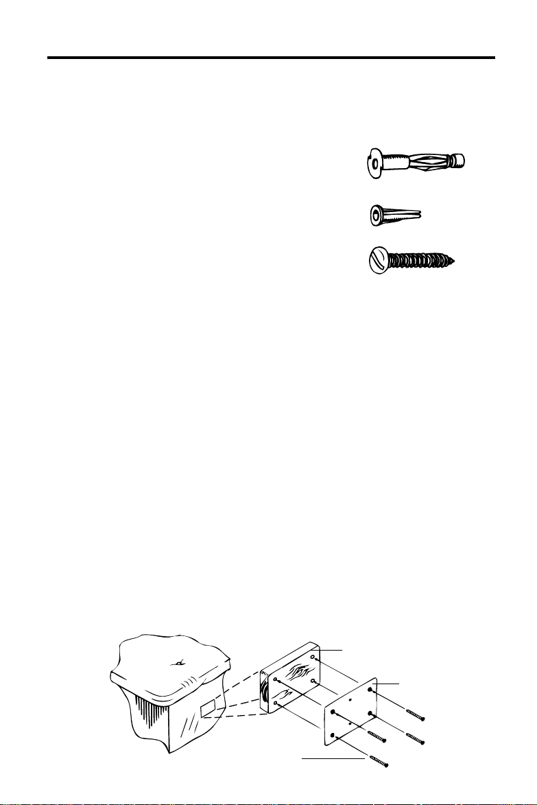
TABLE MOUNTING
NOTE: Some table manufacturers supply table mounting hardware for mounting the
Exam Light II. Check with your table supplier for availability.
• Determine side of table for mounting the Exam Light II.
• Trace the outline of the mounting plate and mark the hole locations on a
1.00 inch (2.5 cm) thick piece of wood.
• Cut the piece of wood to the outline size and drill four .25 inch (.64 cm) holes.
• Using the mounting plate as template, mark the hole locations on the table and
drill four .25 inch (.64 cm) holes.
NOTE: Be sure mounting location is at least 10 inches (25.4 cm) below table cushion,
and that mounting will not obstruct table interior.
• Using four 10-32 x 2 inch (5.08 cm) machine screws with lock washers and nuts,
install the block of wood and the mounting plate to the table as shown in diagram.
• Mount unit as with wall mounting.
Wood Block
Mounting Plate
2 Inch (5.08 cm)
Long Screws
2
Page 3
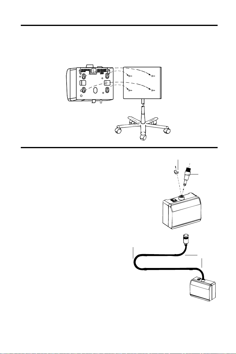
MOUNTING
M
OBILE MOUNTING
• Mount unit by fitting key hole slots on back of unit over screw heads.
• Push unit against mounting plate while pushing down to lock screw heads into
small end of key hole slots.
SET UP
• Carefully remove plastic plug from light pipe holder on top of unit.
• Insert fiber optic light pipe into light pipe holder until it is secure.
• Plug power cord into base of unit and into AC grounded outlet.
• Position the power switch located on the top of the unit to ON.
Plug
NOTE: Please refer to use of light pipe section
prior to using unit.
Max.
180°
To ensure long unit life, high light output and continued position rigidity, we
recommend that you do not acutely
bend the Light Pipe. For example: Middle
Bend—not more than 180°. End Bends—
not more than 90° each.
WARNING:
Not for use in the presence of flammable anesthetic.
Do not use Model 48200 (Standard model) Light Pipe for neonate transillumination.
Even though the distal end of the light pipe does not feel warm to the touch, it can
burn neonates. Erythema may result from contact of more than 15 seconds. Use
Model 48210 Neonate Transilluminator for safe transillumination.
Light
Pipe
Max. 90°
3
Page 4

OPERATION OF LIGHT PIPE
The flexible portions of the fiber optic Light Pipe are designed to be bent, but not
twisted. Twisting, or torque, will decrease the life of the flexible portions, causing
drooping of the Light Pipe and eventual breakage of the fiber optics. As in the illustration, once a section is bent into position A, for example, it must first be returned
to the neutral position before bending into position B. This prevents the twisting motion
of moving directly from A to B that could prove harmful to the unit. For best response,
always position the fiber optic Light Pipe by moving in the same direction as gravity. If
the fiber optic bundle needs to be raised, raise it above the desired position and then
lower to the desired position.
Position A
Neutral
Position
Position B
SPECIAL NOTE: Upon manufacture, the Light Pipe is tested to assure maintenance
of position and absence of noise. Over a period of time it is normal for the Light Pipe to
soften and become less obedient. Abnormal softening or occurrence of noise should be
reported to Welch Allyn.
WARNING:
When pulling out the Light Pipe, push down on the light box to avoid
lifting it off of the mounting plate and possibly dropping it.
NEONATE TRANSILLUMINATOR
O. 48210
N
Use in place of Model 48200 for neonatal transillumination.
The neonate transilluminator is useful for transilluminating neonates as a means to help
diagnose pneumothorax, locate blood vessels, etc.
This transilluminator includes filters that prevent skin
temperature rise in excess of 39°F (4°C) when
in contact for five minutes or longer.
4
Page 5

NEONATE TRANSILLUMINATOR
AUTION:
C
Use only Welch Allyn Transilluminator No. 48210 for neonatal transillumination.
SET UP AND OPERATION
Refer to Set Up page for installation steps.
LAMP REPLACEMENT
ARNING:
W
Lamps operate at a high temperature and under pressure may shatter. Do not attempt
to replace lamp while hot. Wait until lamp is cool.
1. Turn power switch to “Off” position, unplug cord from outlet and from Light box.
2. Release interlock by sliding interlock arm to left. Pull lamp holder until lamp is fully
exposed. (Lamp holder will not slide down if Interlock is not released)
Diagram #1.
Diagram #1
Interlock Arm
3. Push release lever down; Diagram #2. Grasp expired lamp by its base and remove
from lamp holder.
4. IMPORTANT: Reposition release lever up to original position prior to installing new
lamp. Replace only with a Welch Allyn Lamp No. 04200.
5. Visually inspect replacement lamp reflector and bulb, and remove any grease or
fingerprints with a clean cloth moistened with alcohol, if required.
6. Slide new lamp into lamp holder socket until it “snaps” into place. Make sure
lamp is securely seated to assure maximum light output.
7. Slide lamp holder back into light box. Reengage interlock by moving arm to
the right.
Diagram #2
WARNING:
When sliding the lamp holder back into the light box, hold the light box down to avoid
pushing it off of the mounting plate and possibly dropping it.
8. Plug line cord back into unit, and into wall outlet.
5
Page 6

CLEANING
L
ENSES
• Remove the focusing sleeve from the fiber optic bundle by unthreading counterclockwise.
• Use a cotton swab soaked in warm water and mild detergent to clean both the
distal end of the fiber optics and the proximal side of the small lens. (See diagram
for locations.)
• Reassemble focusing sleeve to Light Pipe.
• The window may also be cleaned with warm water and mild detergent.
LIGHT PIPE
• To maintain unit cleanliness, use disposable Sheath (No. 52640).
• May be cleaned with a mild detergent and water solution.
Light Pipe
Distal End
Of Fiber Optics
Cotton Swab
Small Lens
Focusing
Sleeve
WARNING:
Do not clean lens or window with alcohol.
LIGHT BOX
Do not Sterilize.
Do not Immerse in Cleaning Solutions.
1. Unplug the unit from the wall outlet prior to cleaning.
2. Insert the red plastic plug into the Light Pipe socket
prior to cleaning. This will prevent the cleaning solution
from getting into the filter inside the unit.
3. Wipe the surfaces of the unit with a cloth dampened in
a mild solution of detergent and water. Wipe dry with a
clean, dry cloth.
4. The power cord may be wiped clean using the same detergent solution as the
box. Care must be taken not to get the plug prongs wet. Wipe dry with a clean,
dry cloth.
5. Do not plug the unit back into the wall outlet until it is thoroughly dry.
6
Page 7

MAINTENANCE
ENERAL
G
Periodic electric inspections should be made by qualified personnel.
LEAKAGE CURRENT TEST
The leakage current measured from any exposed
metal to ground with input voltage of 120v, 60 Hz
(or 240v, 50 Hz) and the ground wires securely connected shall not exceed .0475v max. or 50 ma.
GROUND CONTINUITY
The resistance measured from the ground pin of the
plug to the exposed metal on unit should be 1.6v max.
Unit
10.2
10000
15 mf d
V
High Impedance
VTVM
REPAIR
For repair by qualified personnel, contact your local authorized Welch Allyn distributor,
or contact Welch Allyn directly at (315) 685-4560.
SPECIFICATIONS
Model No. 48600
Model No. 48625
2
Power Cord—3 x 10 mm
Model Input Output Slowblo 250V
48600 120 VAC, 60 Hz, 0.35A 12 VAC, 3.0A 500 MA
48620 100 VAC, 50/60 Hz, 0.42A 12 VAC, 3.0A 630 MA
48622 220 VAC, 50 Hz, 0.19A 12 VAC, 3.0A 200 MA
48624 240 VAC, 50 Hz, 0.18A 12 VAC, 3.0A 200 MA
48626 240 VAC, 50 Hz, 0.18A 12 VAC, 3.0A 200 MA
Supplied with 4 foot (122 cm) Fiber Optic Light Pipe.
Weight—Approximately 5.5 pounds (2.5 KGms) without mounting plate and
Light Pipe.
Dimensions:
H: 7.25 inches (18.42 cm)
W: 7.625 inches (19.37 cm)
D: 3.75 inches (9.53 cm)
Leakage Current: Less than
10 microamps from any metal
part when correct ground is
used; less than 100 microamps
from any metal part with
ground disconnected.
The CE mark on this product indicates it has been tested to and conforms with the
provisions noted within the 89/336/EEC electromagnetic compatibility directive.
, #18 AWG, 3 wire grounded cord set, 8 feet (3 meters) long.
Fuse: 2x
Circuit Diagram
Fuse
Fuse
Stepdown
Transformer
Chassis
(Back Plate)
On-Off
Switch
IEC 601-1
TYPE B, CLASS I
CONTINUOUS OPERATION
7
Page 8

WARRANTY
L
IGHT BOX
The Light Box is guaranteed by Welch Allyn against all manufacturing defects.
Welch Allyn will repair or replace, free of charge, any parts of its own manufacture
proven to be defective through causes other than misuse, neglect, damage in
shipment or normal wear.
LIGHT PIPE
The Welch Allyn Fiber Optic Light Pipe is guaranteed not to drift once positioned if
mounted vertically according to the enclosed instructions. This warranty is for a
two-year period from original date of purchase provided the Light Pipe has not
been tampered with or abused. Any Welch Allyn Fiber Optic Light Pipe which proves
to drift once positioned, will be repaired or replaced without charge upon receipt of
the unit, prepaid.
Welch Allyn, Inc.
Medical Division
4341 State Street Road
P.O. Box 220
Skaneateles Falls, NY 13153-0220
U.S.A.
Telephone: (315) 685-4560
Fax: (315) 685-3361
Printed in U.S.A. Part No. 488430-2
 Loading...