

Page 1
Welch Allyn
®
H12+™
12-lead Holter
User Manual
CAUTION: Federal law restricts this device to sale by or on the order of a physician.
Page 2

© Copyright 2019, Welch Allyn. All rights are reserved. To support the intended use of the product
described in this publication, the purchaser of the product is permitted to copy this publication, for internal
distribution only, from the media provided by Welch Allyn. No other use, reproduction, or distribution of
this publication, or any part of it, is permitted without written permission from Welch Allyn. Welch Allyn
assumes no responsibility for any injury to anyone, or for any illegal or improper use of the product, that
may result from failure to use this product in accordance with the instructions, cautions, warnings, or
statement of intended use published in this manual. Unauthorized copying of this publication may not only
infringe copyright but also reduce the ability of Welch Allyn to provide accurate and up-to-date information
to users and operators alike. Software: 2019 v5.0.0
Welch Allyn®, H12+™ and HScribe® are registered trademarks of Welch Allyn.
The information contained in this manual is subject to change without notice.
All changes will be in compliance with regulations governing manufacture of medical equipment.
For patent information, please visit www.welchallyn.com/patents
For information about any Welch Allyn product, visit: https://www.welchallyn.com/en/about-
us/locations.html
Customer Service and Technical Support: https://www.welchallyn.com/en/other/contact-us.html
1.888.667.8272, mor_tech.support@hillrom.com
80025606 Ver. A
Revision date: 2019-07
901141 HOLTER RECORDER
EU IMPORTER
Welch Allyn, Inc.
4341 State Street Road
Skaneateles Falls, NY 13153 USA
welchallyn.com
Welch Allyn Limited
Navan Business Park, Dublin Road,
Navan, Co. Meath C15 AW22
Ireland
Page 3

i
TABLE OF CONTENTS
SERVICE AND SPARE PARTS ................................................................................................................................... 1
ASSISTANCE AND PARTS ................................................................................................................................................... 1
REPAIRS ........................................................................................................................................................................ 1
PACKING INSTRUCTIONS: .................................................................................................................................................. 1
NOTICES ................................................................................................................................................................. 3
MANUFACTURER’S RESPONSIBILITY .................................................................................................................................... 3
RESPONSIBILITY OF THE CUSTOMER .................................................................................................................................... 3
EQUIPMENT IDENTIFICATION ............................................................................................................................................. 3
COPYRIGHT AND TRADEMARK NOTICES ............................................................................................................................... 3
OTHER IMPORTANT INFORMATION ..................................................................................................................................... 3
WARRANTY INFORMATION ................................................................................................................................... 5
LIMITED WARRANTY STATEMENT ....................................................................................................................................... 5
USER SAFETY INFORMATION ................................................................................................................................. 7
EQUIPMENT SYMBOLS AND MARKINGS .............................................................................................................. 11
GENERAL CARE .................................................................................................................................................... 13
PRECAUTIONS .............................................................................................................................................................. 13
INSPECTION ................................................................................................................................................................. 13
CLEANING AND DISINFECTION ......................................................................................................................................... 13
ELECTROMAGNETIC COMPATIBILITY (EMC) ......................................................................................................... 15
GUIDANCE AND MANUFACTURER’S DECLARATION: ELECTROMAGENTIC EMISSIONS .................................................................. 16
GUIDANCE AND MANUFACTURER’S DECLARATION: ELECTROMAGNETIC IMMUNITY ................................................................... 16
GUIDANCE AND MANUFACTURER’S DECLARATION: ELECTROMAGNETIC IMMUNITY ................................................................... 17
RECOMMENDED SEPARATION DISTANCES BETWEEN PORTABLE AND MOBILE RF COMMUNICATIONS EQUIPMENT AND THE EQUIPMENT
................................................................................................................................................................................. 18
INTRODUCTION ................................................................................................................................................... 19
MANUAL PURPOSE ....................................................................................................................................................... 19
AUDIENCE ................................................................................................................................................................... 19
INDICATIONS FOR USE ................................................................................................................................................... 19
H12+ RECORDER DESCRIPTION ....................................................................................................................................... 20
RECORDER SETUP ......................................................................................................................................................... 21
USING THE KEYPAD ....................................................................................................................................................... 22
LEADFORM PATIENT CABLE ............................................................................................................................................ 22
H12+ RECORDER IN CARRYING CASE ................................................................................................................................ 23
PART NUMBERS ........................................................................................................................................................... 24
SPECIFICATIONS ............................................................................................................................................................ 25
PATIENT PREPARATION ....................................................................................................................................... 27
PATIENT HOOKUP ......................................................................................................................................................... 27
USING THE RECORDER ......................................................................................................................................... 29
Page 4

TABLE OF CONTENTS
ii
INSERTING AND REMOVING SD CARDS .............................................................................................................................. 29
ATTACHING THE PATIENT CABLE ...................................................................................................................................... 29
MAIN MENU OPTIONS .................................................................................................................................................. 30
STARTING A RECORDING SESSION .................................................................................................................................... 31
ENDING A RECORDING SESSION ....................................................................................................................................... 34
CONFIGURING THE RECORDER ............................................................................................................................. 35
CONFIGURATION .......................................................................................................................................................... 35
SETTING DATE AND TIME ............................................................................................................................................... 37
SETTING LANGUAGE ...................................................................................................................................................... 37
VIEWING SOFTWARE VERSION NUMBER ........................................................................................................................... 37
CHANGING SAMPLE RATE (HIGH-FIDELITY SD CARD ONLY) ................................................................................................... 38
CHANGING DURATION ................................................................................................................................................... 38
MAINTENANCE .................................................................................................................................................... 39
PERIODIC MAINTENANCE ............................................................................................................................................... 41
PRODUCT LIFE .............................................................................................................................................................. 41
DISPOSAL OF WASTE MATERIALS ..................................................................................................................................... 41
TROUBLESHOOTING............................................................................................................................................. 43
TABLE OF MESSAGES ..................................................................................................................................................... 43
TRANSLATIONS .................................................................................................................................................... 45
TABLE OF TRANSLATIONS ............................................................................................................................................... 45
Page 5

1
SERVICE AND SPARE PARTS
Assistance and Parts
If the product fails to function properly or if assistance, service or spare parts are required, contact the
nearest Welch Allyn Technical Support Center.
USA
Latin America
European Call Center
Italy
United Kingdom
France
Germany
Netherlands
1-800-535-6663
(+1) 305-669-9003
(+353) 46-90-67790
(+39) 051-298-7811
(+44) 207-365-6780
(+33) 1-55-69-58-49
(+49) 695-098-5132
(+31) 202-061-360
Canada
South Africa
Australia
Singapore
Japan
China
Sweden
1-800-561-8797
(+27) 11-777-7555
(+61) 2-9638-3000
(+65) 6419-8100
(+81) 42-703-6084
(+86) 21-6327-9631
(+46) 85-853-65-51
When calling, please be prepared to provide:
Product name and model number and complete description of the problem
The serial number of your product (if applicable)
The complete name, address and phone number of your facility
For out-of-warranty repairs or spare parts orders, a purchase order (or credit card) number
For parts order, the required spare or replacement part number(s)
Repairs
All repairs on products under warranty must be performed or approved by Welch Allyn. Unauthorized
repairs will void the warranty. In addition, whether or not covered under warranty, any product repair shall
exclusively be performed by Welch Allyn certified service personnel.
If your product requires warranty, extended warranty, or non-warranty repair service, please call first the
nearest Welch Allyn Technical Support Center. A representative will assist you in troubleshooting the
problem and will make every effort to solve it over the phone, avoiding potential unnecessary returns.
In case the return cannot be avoided, the representative will record all necessary information and will
provide a Return Material Authorization (RMA) number, as well as the appropriate return address. A
Return Material Authorization (RMA) number must be obtained prior to any return.
Packing Instructions:
Remove patient cable, battery, and Secure Digital memory card (as appropriate) prior to packing, unless
you suspect they are associated with the problem.
Whenever possible, use the original shipping carton and packing materials.
Include a packing list and the Welch Allyn Return Material Authorization (RMA) number.
It is recommended that all returned goods be insured. Claims for loss or damage to the product must be
initiated by the sender.
Page 6

SERVICE AND SPARE PARTS
2
Page 7

3
NOTICES
Manufacturer’s Responsibility
Welch Allyn is responsible for the effects on safety and performance only if:
• Assembly operations, extensions, readjustments, modifications, or repairs are carried out only by
persons authorized by Welch Allyn.
• The device is used in accordance with the instructions for use.
Responsibility of the Customer
The user of this device is responsible for ensuring the implementation of a satisfactory maintenance
schedule. Failure to do so may cause undue failure and possible health hazards.
Equipment Identification
Welch Allyn equipment is identified by a serial and reference number on the back of the device. Care
should be taken so that these numbers are not defaced.
Copyright and Trademark Notices
This document contains information that is protected by copyright. All rights are reserved. No part of this
document may be photocopied, reproduced, or translated to another language without prior written
consent of Welch Allyn.
Other Important Information
The information in this document is subject to change without notice.
Welch Allyn makes no warranty of any kind with regard to this material including, but not limited to,
implied warranties of merchantability and fitness for a particular purpose. Welch Allyn assumes no
responsibility for any errors or omissions that may appear in this document. Welch Allyn makes no
commitment to update or to keep current the information contained in this document.
Page 8

NOTICES
4
Page 9

5
WARRANTY INFORMATION
Limited Warranty Statement
Welch Allyn warrants that the Welch Allyn H12+ Holter recorder you have purchased meets the labeled
specifications of the product and will be free from defects in materials and workmanship that occur within
1 year after the date of purchase. Accessories used with the Product are warranted for 90 days after the
date of purchase.
The date of purchase is: 1) the date specified in our records, if you purchased the Product directly from
us, 2) the date specified in the warranty registration card that we ask you to send to us, or 3) if you don’t
return the warranty registration card, 120 days after the date on which the Product was sold to the dealer
from whom you bought the Product, as documented in our records.
This warranty does not cover damage caused by: 1) handling during shipping, 2) use or maintenance
contrary to labeled instructions, 3) alteration or repair by anyone not authorized by Welch Allyn, and 4)
accidents.
You assume all responsibility for the use of the Product with any accessory that does not meet the
requirements described in the Product documentation.
If a product or accessory covered by this warranty is determined to be defective because of defective
materials, components, or workmanship, and the warranty claim is made within the warranty period
described above, Welch Allyn will, at its discretion, repair or replace the defective Product or accessory
free of charge.
You must obtain a return authorization from Welch Allyn to return your Product before you send it to
Welch Allyn’s designated service center for repair.
THIS WARRANTY IS IN LIEU OF ALL OTHER WARRANTIES, EXPRESS OR IMPLIED, INCLUDING
BUT NOT LIMITED TO THE IMPLIED WARRANTIES OF MERCHANTABILITY AND FITNESS FOR A
PARTICULAR PURPOSE. WELCH ALLYN’S OBLIGATION UNDER THIS WARRANTY IS LIMITED TO
REPAIR OR REPLACEMENT OF PRODUCTS CONTAINING A DEFECT. WELCH ALLYN IS NOT
RESPONSIBLE FOR ANY INDIRECT OR CONSEQUENTIAL DAMAGES RESULTING FROM A
PRODUCT DEFECT COVERED BY THE WARRANTY.
Page 10

WARRANTY INFORMATION
6
Page 11

7
USER SAFETY INFORMATION
WARNING:
Means there is the possibility of personal injury to you or others.
Caution:
Means there is the possibility of damage to the device.
Note:
Provides information to further assist in the use of the device.
WARNING(S)
This manual gives important information about the use and safety of this device. Deviating from
operating procedures, misuse or misapplication of the device, or ignoring specifications and
recommendations could result in increased risk of harm to users, patients and bystanders, or damage to
the device.
Any serious incident that has occurred in relation to the H12+ should be reported to Welch Allyn and the
competent authority of the Member State in which the user or patient is established.
Caretakers must closely supervise an infant or child who is wearing a Holter recorder to ensure the
recorder is intact and the patient cable is properly secured.
Device stores data reflecting a patient’s physiological condition to a properly equipped analysis system
that when reviewed by a trained physician or clinician can be useful in determining a diagnosis; however,
the data should not be used as a sole means for determining a patient’s diagnosis.
Users are expected to be licensed clinical professionals knowledgeable about medical procedures
and patient care, and adequately trained in the use of this device. Before attempting to use this
device for clinical applications, the operator must read and understand the contents of the user
manual and other accompanying documents. Inadequate knowledge or training could result in
increased risk of harm to users, patients and bystanders, or damage to the device. Contact Welch
Allyn service for additional training options.
To maintain designed operator and patient safety, peripheral equipment and accessories that can
come in direct patient contact must be in compliance with UL 60601-1, IEC 60601-1, and IEC 606012-47. Only use parts and accessories supplied with the device and available through Welch Allyn.
Patient cables intended for use with the device include series resistance (9 Kohm minimum) in each
lead for defibrillation protection. Patient cables should be checked for cracks or breakage prior to
use.
Conductive parts of the patient cable, electrodes, and associated connections of type CF applied
parts, including the neutral conductor of the patient cable and electrodes, should not come into
contact with other conductive parts including earth ground.
ECG electrodes could cause skin irritation; patients should be examined for signs of irritation or
inflammation.
To avoid the possibility of serious injury or death during patient defibrillation, do not come in contact
with device or patient cables. Additionally, proper placement of defibrillator paddles in relation to the
electrodes is required to minimize harm to the patient.
Defibrillation protection is guaranteed only if the original patient cable is used. Any modification of
this device may alter defibrillator protection.
Page 12

USER SAFETY INFORMATION
8
This device was designed to use the electrodes specified in this manual. Proper clinical procedure
must be employed to prep the electrode sites and to monitor the patient for excessive skin irritation,
inflammation, or other adverse reactions.
Carefully route cables to reduce any possibility of patient entanglement or strangulation.
Simultaneous connection to other equipment may increase leakage current.
To avoid potential for spread of disease or infection, single-use disposable components (e.g.,
electrodes) must not be reused. To maintain safety and effectiveness, electrodes must not be used
beyond their expiration date.
FCC Warning (Part 15.21): Changes or modifications not expressly approved by the party
responsible for compliance could void the user’s authority to operate the device.
A possible explosion hazard exists. Do not use the device in the presence of a flammable anesthetic
mixture.
The device has not been designed for use with high-frequency (HF) surgical equipment and does not
provide a protective means against hazards to the patient.
The quality of the signal produced by the device may be adversely affected by the use of other
medical equipment, including but not limited to defibrillators and ultrasound machines.
There is no known safety hazard if other equipment, such as pacemakers or other stimulators, is
used simultaneously with the device; however, disturbance to the signal may occur.
Operations may be affected in the presence of strong electromagnetic sources such as
electrosurgery equipment.
The device is restricted to use on one patient at a time.
The performance of the device may be compromised by excessive motion.
Use only recommended battery cells. Use of other cells may present a risk of fire or explosion.
Page 13

USER SAFETY INFORMATION
9
Caution(s)
The H12+ recorder is not waterproof. It may be placed in an optionally available sealed, clear pouch
that will protect it from moisture, but should not be submerged in water.
To prevent possible damage to the device, do not use sharp or hard objects to depress buttons, only
use fingertips.
To prevent pinching, press down on the battery door latch when removing and replacing the battery
door.
Do not attempt to clean the device or patient cables by submersing into a liquid, autoclaving, or steam
cleaning as this may damage equipment or reduce its usable life. Use of unspecified
cleaning/disinfecting agents, failure to follow recommended procedures, or contact with unspecified
materials could result in increased risk of harm to users, patients and bystanders, or damage to the
device. Do not sterilize the device or patient cables with Ethylene Oxide (EtO) gas.
The device and patient cable should be cleaned between each use. Inspect cable and connection for
damage or excessive wear prior to each use. Replace cable if damage or excessive wear is noted.
Do not pull or stretch patient cables as this could result in mechanical and/or electrical failures.
Patient cables should be stored after forming them into a loose loop.
The device will only work with devices that are equipped with the appropriate option.
Do not format the SD Card using standard Microsoft Windows formatting conventions on the
computer. This will cause the SD card to be non-functional for Holter recording.
When removing the SD card from the system card reader, it is recommended to use the “Safely
Remove Hardware and Eject Media” feature on the computer to reduce the possibility of SD card
errors.
No user-serviceable parts are inside. Damaged or suspected inoperative equipment must be
immediately removed from use and must be checked/repaired by qualified service personnel prior to
continued use.
This device is not recommended for use in the presence of imaging equipment such as Magnetic
Resonance Imaging (MRI) and Computed Tomography (CT) devices, etc.
When necessary, dispose of the device, its components and accessories (e.g., batteries, cables,
electrodes), and/or packing materials in accordance with local regulations.
AA batteries are known to leak their contents when stored in unused equipment. Remove battery
from device when not used for an extended period of time.
To prevent possible damage to the device, the following environmental conditions must be adhered to:
Operating Temperature: +10 to +45C
Storage Temperature: -40 to +70C
Relative Humidity: 10 to 95%, non-condensing
Ambient Air Pressure: 700 to 1060 millibars
Page 14

USER SAFETY INFORMATION
10
Note(s)
Proper patient preparation is important to proper application of ECG electrodes and operation of the
device.
If electrode is not properly connected to the patient, or one or more of the patient cable lead wires is
damaged, display will indicate a lead fault for the lead(s) where the condition is present.
The device is set to the U.S. Central Time Zone when shipped from the factory. If a change is required,
set the correct date and time prior to using the recorder. Refer to the instructions within this user manual.
The patient cable life expectancy is six months continuous use with proper care.
Complete lead fail will cause a greater draw on battery power which may cause the recording period
to end early due to low-battery voltage.
If during power up the battery voltage is below 1.45V, the recorder will display a low battery message
and will not continue.
The device will automatically turn off (blank screen) if the batteries have been severely discharged.
No preliminary or ongoing scheduled periodic calibration by the user or Welch Allyn personnel is
required. The design for the device is such that the system contains no elements requiring
calibration.
The device conforms to the following standards:
IEC 60601-1: Edition 3.1 2012-08 General requirements for basic Safety and essential
performance
IEC 60601-2-47: Edition 2.0 2012-02* Particular requirements for safety, including essential
performance, of ambulatory electrocardiographic
systems
IEC 60601-1-2: Third Edition 2007-03 Electromagnetic Compatibility
IEC 62304:2006/A1:2015 Software life-cycle processes
IEC 62366:2015 Application of usability engineering
93/42/EEC Medical Device Directive (MDD)
2012/19/EU Waste Electrical and Electronic Equipment
ISO 10993-1:2009/Cor. 1:2010 Biological evaluation of medical devices
* Pacemaker spikes < 0.1 milliseconds may not always be detected.
The device is UL classified:
MEDICAL — PATIENT-MONITORING EQUIPMENT AS TO ELECTRICAL
SHOCK, FIRE AND MECHANICAL HAZARDS ONLY IN ACCORDANCE WITH
ANSI/AAMI ES60601-1 (2005) + AMD 1 (2012), IEC 60601-1 (2012), CAN/CSA
C22.2 No. 60601-1 (2014) AND IEC 60601-2-47 (2012).
Page 15
11
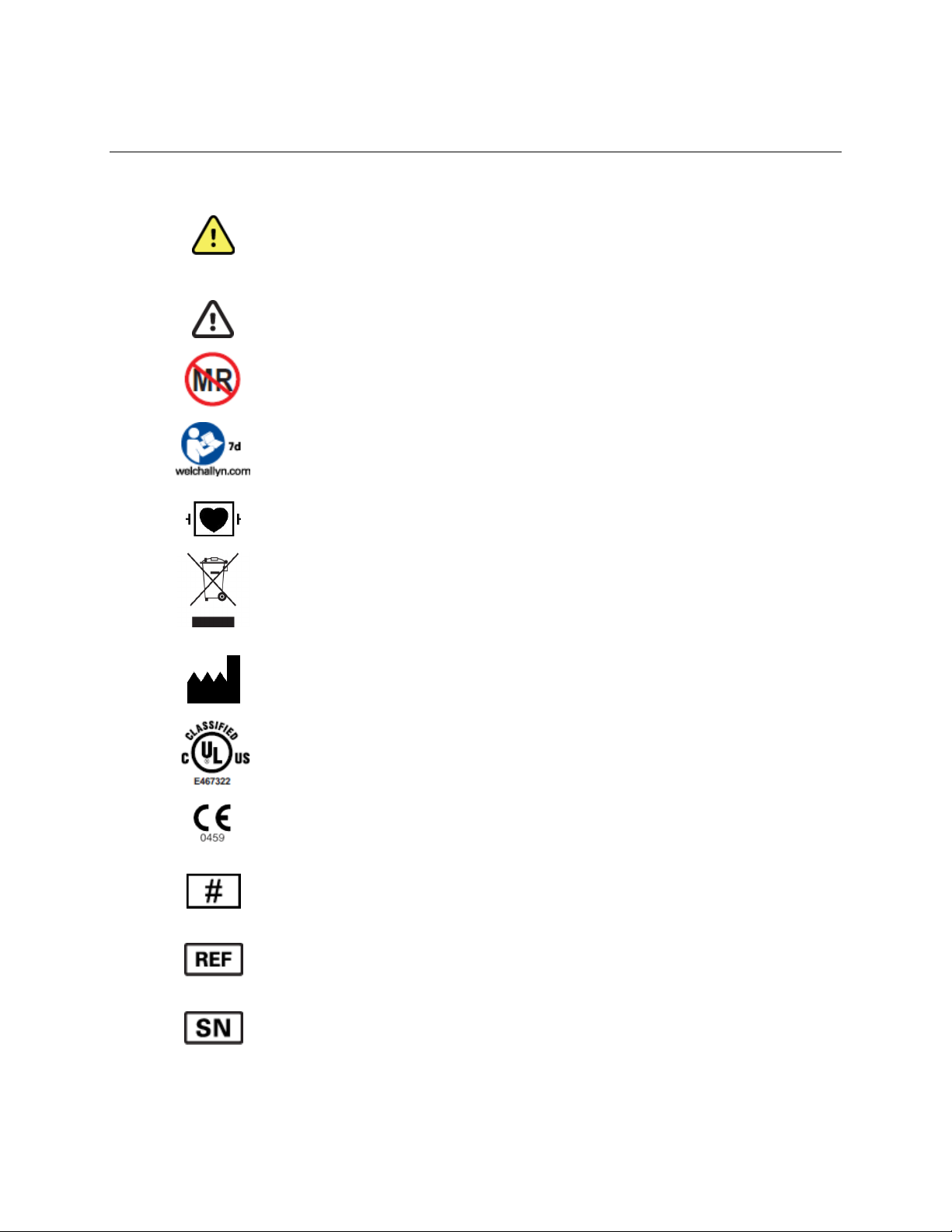
EQUIPMENT SYMBOLS AND MARKINGS
WARNING The warning statements in this manual identify
conditions or practices that could lead to illness, injury, or death. In
addition, when used on a patient applied part, this symbol indicates
defibrillation protection is in the cables. Warning symbols will
appear with a grey background in a black and white document.
CAUTION The caution statements in this manual identify conditions
or practices that could result in damage to the equipment or other
property, or loss of data.
Warning: Do not use this equipment in the MRI scan room.
Follow instructions/directions for use (DFU) -- mandatory action. A
copy of the DFU is available on this website. A printed copy of the
DFU can be ordered from Welch Allyn for delivery within 7 calendar
days.
Defibrillator-proof type CF applied part
Do not dispose as unsorted municipal waste. Requires separate
handling for waste disposal according to local requirements.
Device Manufacturer
Device is UL classified.
Indicates compliance to applicable EEC directives.
Model Identifier
Reorder Number
Serial Number
Page 16

EQUIPMENT SYMBOLS AND MARKINGS
12
Global Trade Item Number
Battery orientation and size
Medical Device
Page 17

13
GENERAL CARE
Precautions
Turn off the device before inspecting or cleaning.
The H12+ recorder is not waterproof. It may be placed in an optionally available sealed, clear
pouch that will protect it from moisture, but should not be submerged in water.
Do not use organic solvents, ammonia-based solutions, or abrasive cleaning agents which may
damage equipment surfaces.
Inspection
Inspect your equipment daily prior to operation. If you notice anything that requires repair, contact an
authorized service person to make the repairs.
Verify that all cables and connectors are securely seated.
Check the case for any visible damage.
Inspect cables and connectors for any visible damage.
Inspect buttons and controls for proper function and appearance.
Cleaning and Disinfection
Refer to Maintenance for proper cleaning and disinfection procedures.
Page 18

GENERAL CARE
14
Page 19

15
ELECTROMAGNETIC COMPATIBILITY (EMC)
Electromagnetic compatibility with surrounding devices should be assessed when using the device.
An electronic device can either generate or receive electromagnetic interference. Testing for
electromagnetic compatibility (EMC) has been performed on the device according to the international
standard for EMC for medical devices (IEC 60601-1-2). This IEC standard has been adopted in Europe
as the European Norm (EN 60601-1-2).
The device should not be used adjacent to, or stacked on top of other equipment. If the device must be
used adjacent to or stacked on top of other equipment, verify that the device operates in an acceptable
manner in the configuration in which it will be used.
Fixed, portable, and mobile radio frequency communications equipment can affect the performance of
medical equipment. See appropriate EMC table for recommended separation distances between the
radio equipment and the device.
The use of accessories and cables other than those specified by Welch Allyn may result in increased
emissions or decreased immunity of the device.
Page 20

ELECTROMAGNETIC COMPATIBILITY (EMC)
16
Guidance and Manufacturer’s Declaration: Electromagentic Emissions
The equipment is intended for use in the electromagnetic environment specified in the table below. The
customer or the user of the equipment should ensure that it is used in such an environment.
Emissions Test
Compliance
Electromagnetic Environment: Guidance
RF Emissions
CISPR 11
Group 1
The equipment uses RF energy only for its internal
function. Therefore, its RF emissions are very low and
are not likely to cause any interference in nearby
electronic equipment.
RF Emissions
CISPR 11
Class B
The equipment is suitable for use in all establishments,
including domestic establishments and those directly
connected to the public low-voltage power supply network
that supplies buildings used for domestic purposes.
Harmonic Emissions
IEC 61000-3-2
Not Applicable
Voltage Fluctuations/
Flicker Emissions
IEC 61000-3-3
Not Applicable
Guidance and Manufacturer’s Declaration: Electromagnetic Immunity
The equipment is intended for use in the electromagnetic environment specified in the table below. The
customer or the user of the equipment should ensure that it is used in such an environment.
Immunity Test
Compliance
Compliance Level
Electromagnetic Environment: Guidance
Electrostatic
discharge (ESD)
IEC 61000-4-2
+/- 6 kV contact
+/- 8 kV air
+/- 6 kV contact
+/- 8 kV air
Floors should be wood, concrete, or ceramic
tile. If floors are covered with synthetic
material, the relative humidity should be at
least 30%.
Electrical fast
transient/burst
IEC 61000-4-4
Not Applicable
Not Applicable
Surge
IEC 61000-4-5
Not Applicable
Not Applicable
Voltage dips,
short
interruptions,
and voltage
variations on
power supply
input lines
IEC 61000-4-11
Not Applicable
Not Applicable
Power frequency
(50/60 Hz)
magnetic field
3 A/m
3 A/m
Power frequency magnetic fields should be at
levels characteristic of a typical location in a
typical commercial or hospital environment.
NOTE: UT is the AC Mains voltage prior to application of the test level.
Page 21

ELECTROMAGNETIC COMPATIBILITY (EMC)
17
Guidance and Manufacturer’s Declaration: Electromagnetic Immunity
The equipment is intended for use in the electromagnetic environment specified in the table below. The
customer or the user of the equipment should ensure that it is used in such an environment.
Immunity Test
IEC 60601 Test
Level
Compliance
Level
Electromagentic Environment: Guidance
Conducted RF
IEC 61000-4-6
3 Vrms
150 kHz to
80 MHz
3 Vrms
150 kHz to
80 MHz
Portable and mobile RF communications equipment
should be used no closer to any part of the equipment,
including cables, than the recommended separation
distance calculated from the equation applicable to the
frequency of the transmitter.
Recommended separation distance
P
Vrms
d
3
5.3
P
mV
d
/3
5.3
80 MHz to 800 MHz
P
mV
d
/3
7
800 MHz to 2.5 GHz
Where P is the maximum output power rating of the
transmitter in watts (W) according to the transmitter
manufacturer and d is the recommended separation
distance in meters (m).
Field strengths from fixed RF transmitters, as
determined by an electromagnetic site surveya, should
be less than the compliance level in each frequency
rangeb.
Interference may occur in the vicinity of equipment
marked with the following symbol:
Radiated RF
IEC 61000-4-3
3 V/m
80 MHz to
2.5 GHz
3 V/m
80 MHz to
2.5 GHz
a. Field strengths from fixed transmitters, such as base stations for radio (cellular/cordless) telephones and land
mobile radios, amateur radios, AM and FM radio broadcast, and TV broadcast cannot be predicted theoretically
with accuracy. To assess the electromagnetic environment due to fixed RF transmitters, an electromagnetic site
survey should be considered. If the measured field strength in the location in which the equipment is used
exceeds the applicable RF compliance level above, the equipment should be observed to verify normal operation.
If abnormal performance is observed, additional measures may be necessary, such as reorienting or relocating
the equipment.
b. Over the frequency range 150 kHz to 80 MHz, field strengths should be less than [3] V/m.
Page 22

ELECTROMAGNETIC COMPATIBILITY (EMC)
18
Recommended Separation Distances Between Portable and Mobile RF Communications Equipment and the Equipment
The equipment is intended for use in the electromagnetic environment in which radiated RF disturbances
are controlled. The customer or the user of the equipment can help to prevent electromagnetic
interference by maintaining a minimum distance between portable and mobile RF communications
equipment (transmitters) and the equipment as recommended in the table below, according to the
maximum output power of the communications equipment.
Rated Maximum Output Power
of Transmitter W
Separation Distance According to Frequency of Transmitter (m)
150 KHz to 800 MHz
800 MHz to 2.5 GHz
Pd 2.1
Pd 3.2
0.01
0.1 m
0.2 m
0.1
0.4 m
0.7 m
1
1.2 m
2.3 m
10
4.0 m
7.0 m
100
12.0 m
23.0 m
For transmitters rated at a maximum output power not listed above, the recommended separation
distance d in meters (m) can be estimated using the equation applicable to the frequency of the
transmitter, where P is the maximum output power rating of the transmitter in watts (W) according to the
transmitter manufacturer.
NOTE 1: At 800 MHz, the separation distance for the higher frequency range applies.
NOTE 2: These guidelines may not apply in all situations. Electromagnetic propagation is
affected by the absorption and reflection from structures, objects, and people.
Page 23

19
INTRODUCTION
Manual Purpose
This manual explains how to operate the 12-lead H12+™ digital Holter recorder. It shows the user how
to:
Prepare the patient
Use the recorder
Configure the recorder
Troubleshoot
Audience
This manual is written for clinical professionals who are expected to have a working knowledge of medical
procedures and terminology as required for monitoring cardiac patients.
Indications for Use
The H12+ Holter recorder is intended to acquire, record and store ECG data of patients that have been
connected to the H12+ recorder and are undergoing Holter monitoring. The H12+ acquires, digitizes and
stores data to be analyzed by the HScribe Holter system.
The H12+ is indicated for use in a clinical setting, by qualified medical professionals only, for
recording ECG data of symptomatic patients requiring ambulatory (Holter) monitoring of up to 48
hours.
The H12+ does not perform cardiac analysis by itself and is intended to be used with the HScribe™
Holter analysis system. ECG data pre-recorded by the H12+ is acquired and analyzed by the
HScribe Holter analysis system.
Page 24

INTRODUCTION
20
H12+ Recorder Description
An LCD screen allows for checking the settings for recording duration, ECG sampling rate, impedance
and lead quality during patient hook-up; a keypad allows for entering of patient ID, setup of configuration
parameters, and starting of recording. The keypad can also be used to enter event markers in the patient
record during recording. The H12+ recorder utilizes the patented LeadForm patient cable.
The H12+ recorder uses a single AA alkaline battery to provide continuous 12-lead data recorded and a
removable secure digital (SD) card for data storage.
A removable standard SD card can be dedicated for use with a particular H12+ recorder.
Along with a fresh AA battery, this will provide continuous 12-lead data recorded at a 180 Hz
sampling rate. A maximum recording duration of 24 hours or 48 hours is a feature of the SD
card selected.
A removable high-fidelity SD card can be dedicated for use with a particular H12+ recorder.
Along with a fresh AA battery, this will provide continuous 12-lead data recorded at a 1,000
Hz sampling rate. A maximum recording duration of 24 hours or 48 hours is a feature of the
SD card selected.
NOTE: High-fidelity data requires a special orderable option for the HScribe system software to export the
1,000 samples per second data.
Page 25

INTRODUCTION
21
Recorder Setup
Opening and Closing the Battery Door The SD card slot and the battery compartment are accessible via the battery door of the H12+ recorder.
To open the battery door, hold the latch (1) down and then depress and slide the battery door (2) until it
stops. Lift and remove the battery door.
To close the battery door, replace the battery door halfway, matching the grooves on the H12+ recorder
as shown in the diagram, and slide in the opposite direction of the arrow (2) until the door latches into
place.
Inserting the Battery
The H12+ recorder is powered with a single AA alkaline battery.
Open the battery door of the H12+ recorder. If needed, remove and discard the old battery. Insert a new
battery with the ‘+’ end aligned with the top of the recorder, as indicated on the back label. Close the
battery door of the recorder.
NOTE: The H12+ recorder requires a full capacity battery to record a 24-hour or 48-hour
session. The H12+ recorder will test battery voltage upon start up and will not allow the
recording to begin if there is insufficient voltage. Always use a new battery to ensure operation.
Page 26

INTRODUCTION
22
Using the Keypad
The keypad is located on the front, right side of the H12+ recorder. Three keys are available for
navigating through the LCD screens and for entering the patient ID and event markers during the
recording: Up/Right, Down, and Enter.
During patient hook-up, Down and Up/Right are used to scroll through the main menu options to enter
the patient ID and to set the date/time and language. Enter is used to select main menu and sub-menu
options displayed on the LCD screen, and to store the patient ID and configuration parameters for
recorder operation.
LeadForm Patient Cable
The LeadForm patient cable consists of a connector block, main cable, and ten lead wires connected to
the main cable. Each lead wire terminates in a snap connector. The lead wires are positioned on the
main cable to follow the contour of the torso.
Page 27

INTRODUCTION
23
H12+ Recorder in Carrying Case
Page 28

INTRODUCTION
24
Part Numbers
Description
Part Numbers
H12+ 24-Hour Recorder with Standard SD Card
H12PLUS-LXX-XXXXX
H12+ 48-Hour Recorder with Standard SD Card
H12PLUS-MXX-XXXXX
H12+ 24-Hour Standard SD Card
107503
H12+ 48-Hour Standard SD Card
107505
H12+ 24-Hour Recorder with High-Fidelity SD Card
H12PLUS-NXX-XXXXX
H12+ 48-Hour Recorder with High-Fidelity SD Card
H12PLUS-OXX-XXXXX
H12+ High-Fidelity 24-Hour SD Card
107504
H12+ High-Fidelity 48-Hour SD Card
107506
H12+ Battery Door
413502
H12+ Carrying Case with Strap and Belt
8485-020-51
LeadForm Patient Cable/Domestic (AHA)
Standard
Large
9293-017-50
9293-026-50
LeadForm Patient Cable/International (IEC)
Standard
Large
9293-017-51
9293-026-51
H12+ User Manual – English
9515-160-51-CD
H12+ Quick Reference Guide – English
9515-160-51-CD
H12+ Holter Hookup Kits 24H – case of 24
9294-010-51
H12+ Holter Hookup Kits 48H – case of 24
9294-011-51
Single Patient Use Clip-on Pouch – case of 100
107179
Page 29

INTRODUCTION
25
Specifications
Feature
Specifications
Instrument Type
12-lead digital Holter recorder
Input Channels
Simultaneous acquisition of all leads
Standard Leads Acquired
I, II, III, aVR, aVL, aVF, V1, V2, V3, V4, V5, and V6
Input Dynamic Range
+/- 300 mV with a resolution of 2.5 µV/LSB
Frequency Response
0.05 to 60 Hz for standard recording
0.05 to 300 Hz for high fidelity recording
Digital Sampling Rate
32,000 s/sec/channel used for pacemaker spike detection
180 s/sec/channel used for standard recording and storage
1,000 s/sec/channel is used for high fidelity recording and storage
Special Functions
Pacemaker detection, ECG display, and lead quality check
A/D Conversion
20 bits
Storage
Secure Digital (SD) memory card
Device Classification
Type CF, battery operated
Weight
4 oz. (125 g) without battery
Dimensions
2.5” x 3.85” x .98” (64 mm x 98 mm x 25 mm)
Batteries
(1) AA alkaline
Page 30

INTRODUCTION
26
Environment
Specifications
Operating Temperature
+10˚ to +45˚C
Storage Temperature
-40˚ to +70˚C
Operating Humidity
10% to 95%, non-condensing
Storage Humidity
10% to 95%, non-condensing
Operating Altitude (Pressure)
H12+ will operate normally from 700 to 1060 millibars
Storage Altitude (Pressure)
500 to 1060 millibars
Water Ingress
IPX0
Page 31

27
PATIENT PREPARATION
Patient Hookup
Skin Preparation
Good skin preparation prior to electrode attachment is very important to ensure good signal quality when
recording patient data. Poor electrode-to-skin contact may cause artifact (noise) to be included in the
recording which can affect the analysis of the ECG data. Low-amplitude signals may also be the result of
poor electrode-to-skin contact.
1. Identify the (10) electrode sites on the torso (refer to the Positioning the Electrodes diagram).
2. Use a clipper or razor to remove any hair from the electrode sites.
3. Clean the skin with soap or alcohol to remove any body oils, lotion, or powder.
4. Use gauze to dry the skin and remove any alcohol residue if used.
5. Use an abrasive pad to gently abrade, but not break, the skin where the center of each electrode will
be applied. This removes dead skin cells that may impede heart signal conduction.
Positioning the Electrodes
6. Attach the electrodes to the lead wires on the patient cable before attaching electrodes to the patient.
7. Firmly attach each lead wire to an electrode.
8. Place the gel area of the electrode over the center of the prepared area using the positioning
illustrated on the next page; press the adhesive ring into place. Avoid pressing the center of the gel
area.
9. Place right arm (RA/R) and left arm (LA/L) leads close to the shoulder on the clavicle bone.
10. Place right leg (RL/N) and left leg (LL/F) leads on the lower portion of body, as close to the hip as
possible, on the iliac crest (original Mason-Likar position), or on the lowest rib on each side of the
chest (modified Mason-Likar position).
11. Ensure electrodes are securely attached to the skin. To test electrode contact, lightly tug the lead
wire to check adhesion. If the electrode moves freely, the site should be prepped again. If the
electrode does not move easily, a good connection has been obtained.
NOTE AND CAUTION: Proper skin preparation is very important. Poor ECG signal quality is
the main cause for incorrect beat and arrhythmia detection. RA and LA are susceptible to muscle
interference. RL and LL leads are susceptible to interference from clothing, a belt, and movement.
Choose the best locations for limb lead placement according to body type. Avoid muscular and
loose, flabby skin locations.
Page 32

PATIENT PREPARATION
28
NOTE AND CAUTION: Placement of the Left Leg (LL) electrode in the original Mason-Likar
position increases the similarity of the acquired ECG with a standard 12-lead ECG and is therefore
recommended; however, clothing may interfere with this position and increase the amount of artifact. The
modified position may decrease the sensitivity of inferior ECG leads and cause axis shift with respect to
the standard 12-lead ECG. Accurate skin preparation and suitable clothing are the most important factors
in excessive artifact prevention.
Limb Electrode
Precordial Electrode
AAMI
IEC
Placement
AAMI
IEC
Placement
RA
R
On or below the right
clavicle as shown
V1
C1
Fourth intercostal space at
the right sternal border
LA
L
On or below the left clavicle
as shown
V2
C2
Fourth intercostal space at
the left sternal border
RL
N
Reference or ground lead,
should be placed in a stable
location of the body
V3
C3
Midway between V2 and V4
LL
F
Lower-left side of body in a
stable location, as close to
the hip as possible
V4
C4
Fifth intercostal space at the
left of the midclavicular line
V5
C5
Anterior axillary line on the
same horizontal level as V4
V6
C6
Mid-axillary line on the same
horizontal level as V4 and V5
Page 33

29
USING THE RECORDER
Inserting and Removing SD Cards
To insert an SD card, open the battery door of the recorder. Position the card above the empty card slot
with the label facing front as shown below. Place the SD card in the slot and gently push down on the
SD card until it is firmly engaged and can move no further.
To remove an SD card, gently push down on the SD card to disengage and eject. The internal card
carrier is spring loaded. Once ejected, grasp the top of the card and lift to remove.
Attaching the Patient Cable
Insert the connector block into the input connector on the side of the H12+ recorder.
NOTE: Be careful to insert the connector block parallel to the input connector.
Page 34

USING THE RECORDER
30
Main Menu Options
The recording set duration from 1 to 48 hours (or 1 to 24 hours) and the Holter ECG sampling rate are
initially displayed upon insertion of the SD card and AA battery once the battery door closed and
initialization has completed. Selection of the Down-arrow key moves to the Lead Check. Selection of the
Up/Right arrow moves to Configure.
The main menu includes the following options:
TARGET RATE / DURATION SETTINGS (view only, changes made in CONFIGURE)
LEAD CHECK
DISPLAY ECG
ENTER ID (or ID# if card is already prepared)
RECORD (see Using the Recorder)
CONFIGURE
The following operational flowchart of menu options depicts the flow of functionality using Up/Right,
Down, and Enter.
The LEAD CHECK, DISPLAY ECG, ENTER ID, and CONFIGURE tasks are performed prior to starting a
new patient recording. With the exception of CONFIGURE, the other tasks are typically reviewed for
each recording.
NOTE: Patient ID entry (ENTER ID) is optional and can be entered during recorder preparation
at HScribe or after the patient record is downloaded to the HScribe system.
Page 35

USING THE RECORDER
31
Starting a Recording Session
1. Insert a proprietary Welch Allyn SD card and a new AA battery.
2. After the battery door is closed, H12+ will power up and perform software and battery tests.
This takes a few seconds while the Hillrom splash screen is displayed. When finished, the
duration and sample rate are displayed.
3. Verify the set duration and sample rate.
a. If necessary, navigate to the CONFIGURE menu
to change the set duration and sample rate (see
Changing Duration and Changing Sample Rate).
4. Hookup the patient (see Patient Preparation).
5. Verify the quality of the hookup by checking the
impedances. Scroll through the main menu until
LEAD CHECK is displayed, press Enter.
Note: Main menu options are displayed in the
middle of the screen with Up ‘▲’ and Down ‘▼’
indicators above and below the option to indicate
how to scroll to the next option. The current time
and date are displayed at the bottom of the LCD
screen.
Checking Impedances
LEAD CHECK is a valuable tool for verifying and optimizing signal quality after patient hookup and
before starting a recording.
From the main menu, scroll to LEAD CHECK, press Enter.
A graph depicting the impedance measured at the
right arm (RA), left arm (LA), left leg (LL), and V1
through V6 electrodes is displayed from left to right in
vertical columns on the screen. The higher the solid
black oval indicator, the better the contact is between
the skin and the electrode.
An oval indicator positioned at the top the vertical
line means optimal high quality and good electrode
contact. For good-quality recordings, the bars
should reach or exceed the horizontal line on the
display. A low bar graph means poor electrode-toskin contact and high-electrode impedance. The
skin preparation should be repeated, and the
electrode(s) replaced.
Once acceptable impedance levels are verified, press
any of the three keys to return to the main menu.
6. Verify the amplitude and signal quality by displaying each of the leads. Scroll through the main menu
until DISPLAY ECG is displayed, press Enter.
Page 36

USING THE RECORDER
32
Displaying ECG Leads
DISPLAY ECG is used to visually inspect leads I, II, III, V1, V2, V3, V4, V5, and V6 before
starting a recording. Check the signal quality and ECG amplitude for each lead.
From the main menu, scroll to DISPLAY ECG, press Enter.
Lead I is the first lead displayed on the screen. Scroll from lead to lead. After visual verification of all
leads, press Enter to return to the main menu.
7. To enter the patient ID, scroll through the main menu until ENTER ID is displayed, press Enter.
NOTE: When Patient ID entry has been performed at the HScribe system and saved to the SD
card, you will not be prompted with “Enter ID”. The patient ID number will be displayed.
NOTE: Unsupported characters are displayed as a question mark (?)
Entering Patient ID
ENTER ID is used to enter the patient ID in the patient record before starting a recording.
Press Enter to select.
To enter the patient ID, the cursor is moved to the
desired letter or digit in the alphanumeric table and
then selected by pressing Enter.
The cursor is initially located in the upper-left corner
of the screen over the number ‘0’. To move the
cursor one letter or digit to the right on a line, press
Up/Right. When the cursor reaches the end of the
line, the cursor wraps to the beginning of the line.
To move the cursor down one line, press Down. If the cursor is on the bottom line, pressing Down
moves the cursor to the top line.
To enter a space, move the cursor to the last line and position the cursor over the blank space
following the last letter. Press Enter.
To delete a letter or digit, position the cursor over Del on the bottom line. Press Enter to delete the
last letter or digit entered. To end entry, position the cursor over End on the bottom line, press the
Enter to end and save.
NOTE: When entering the patient ID, the Up/Right key is used to move the cursor to the right.
The cursor cannot be moved in the left or up direction.
Page 37

USING THE RECORDER
33
8. To begin recording, scroll through the main menu until RECORD is displayed, then press Enter. An
initializing message will be displayed for up to 3 seconds; “Recording” and the current time appear
when the recording actually begins.
During normal operation of a recording, the
current time (HH:MM:SS) is displayed near
the middle of the screen for the entire
recording session. Total hours recorded is
displayed below the current time. The
Recording message is displayed below the
number of total hours recorded; the patient
ID number is displayed at the bottom of the
LCD screen.
NOTE: If the battery door is removed during recording, the H12+ recorder stops recording. A
new proprietary Welch Allyn SD card and fresh battery must be inserted to continue recording.
NOTE: In the event of a lead fail condition occurring during recording, the appropriate lead fail
indicator(s) is displayed below the Recording message and will replace the displayed patient ID
number until resolved. See Appendix A, Troubleshooting, for information on lead fail messages.
Entering (Optional) Diary Events
During the recording session, the patient may be instructed to enter event markers on the H12+ recorder
for analysis purposes. Once entered on the recorder, the patient is instructed to document the time and
symptom in the patient diary. Typical diary events may include symptomatic occurrences, such as
shortness of breath or palpitations, or any event deemed valuable for analysis purposes.
To enter an event after the first minute of recording, press any of the three keys on the H12+ recorder.
An “Event Stored” message is displayed below the current time and will replace the patient ID number
until a new event can be entered.
NOTE: In the event of a simultaneous lead fail event, the Event Stored message replaces the
lead fail message for the one-minute period. If lead fail persists after the one-minute period, the
lead fail message is displayed.
Page 38

USING THE RECORDER
34
Ending a Recording Session
At the end of the set recording duration, the time is automatically cleared from the LCD screen and a
“Recording Complete” message is displayed. To proceed:
1. Remove the battery door of the H12+
recorder.
2. Remove battery and dispose of properly.
(Batteries should only be used once.)
3. Gently press down on the SD card to
eject and then remove the SD card.
Ending a Recording Session Early
The recording session can be stopped at any time by performing the following steps:
1. Simultaneously press and hold Up/Right and
Down for a period of 5 seconds. The LCD
screen will prompt you with a “Stop
Recording” message; “No” is set as the
default.
2. Press Up/Right to move the highlight to
“Yes”.
3. Press Enter to stop recording.
4. A “Recording Complete” message is
displayed.
NOTE: A message is added to the SD card service log indicating that the recording was manually
ended.
Page 39

35
CONFIGURING THE RECORDER
Configuration
CONFIGURE is used to set the current date and time, the date format, the recording duration from 1 to
48-hours or 1 to 24-hours, language defaults, and to display the software version number.
Note: A maximum recording duration of 24 hours or 48 hours is a feature of the SD card selected.
Also, when a High-Fidelity SD card is used, the Holter ECG sampling rate can be set at 1000 samples per
second or 180 samples per second.
These settings are typically set before the initial patient recording and do not need to be set on a per
patient recording basis.
From the main menu, scroll to CONFIGURE, press Enter.
The CONFIGURE menu includes the following options.
DATE/TIME
LANGUAGE
VERSION
SAMPLE RATE
DURATION
DONE
Scroll through the CONFIGURE menu options; press Enter when the desired option is displayed. Select
DONE and Enter to return to the CONFIGURE menu.
The following operational flowchart of CONFIGURE menu options depicts the flow of functionality using
Up/Right, Down, and Enter.
Page 40

CONFIGURING THE RECORDER
36
Page 41

CONFIGURING THE RECORDER
37
Setting Date and Time
DATE/TIME is used to set the current date and time and to set an alternative format for the displayed
date.
From the configuration menu, scroll to DATE/TIME, press Enter. The DATE/TIME menu includes the
following options:
SET MINUTE
SET HOUR
SET DAY
SET MONTH
SET YEAR
FORMAT
DONE
Scroll to the desired option, press Enter. The current values for this option are displayed on the LCD
screen.
When setting the date or time, increase the value by pressing Up/Right. To decrease the value, press
Down. When the correct value is displayed on the screen, press Enter.
NOTE: A SET SECONDS option does not exist because seconds are reset each time a value is
changed. If you want to reset the seconds, set the minutes first. Press Enter at the instant you
want the seconds to be reset.
FORMAT provides two options for the date format: month/day/year or day.month.year.
From the DATE/TIME menu, scroll to FORMAT, press Enter. Scroll from one option to the other; press
Enter to select the desired date format and return to FORMAT menu. Scroll to DONE, press Enter.
To return to the CONFIGURE menu, scroll to DONE, press Enter.
Setting Language
LANGUAGE is used to select a language to view the main and sub-menu options.
From the CONFIGURE menu, scroll to LANGUAGE, press Enter. Scroll through the language options;
press the Enter key to select the desired language and return to the LANGUAGE menu. Scroll to DONE,
press Enter.
Viewing Software Version Number
VERSION displays the current software version installed on the H12+ recorder.
From the CONFIGURE menu, scroll to VERSION using Up/Right or Down; press Enter to view software
version. Press Enter to return to VERSION, scroll to DONE, and press Enter to return to CONFIGURE
menu.
Page 42

CONFIGURING THE RECORDER
38
Changing Sample Rate (High-Fidelity SD card only)
The sample rate is selectable only when using the High-Fidelity SD card which can be set to 1000 or 180
samples per second.
From the CONFIGURE menu, scroll to SAMPLE RATE, press Enter. Scroll to the sample rate desired;
press the Enter key to select and return to the SAMPLE RATE menu. Scroll to DONE, press Enter.
Changing Duration
Duration is used to select recording duration in hour intervals. The maximum selectable recording
duration of 24 hours or 48 hours is a feature of the SD card being used.
From the CONFIGURE menu, scroll to DURATION, press Enter. Scroll to select the desired duration in
hours as value of 1 to 48 or 1 to 24 as dependent on the SD card being used; press the Enter key to
select and return to the DURATION menu. Scroll to DONE, press Enter.
Page 43

39
MAINTENANCE
Cleaning and Disinfecting
This section describes the procedures for cleaning and disinfecting the H12+ and accessories.
WARNING: Follow these instructions to clean and disinfect the H12+ and its accessories.
Improper cleaning may cause damage that is not immediately apparent, leading to possible
safety hazards, device malfunction, and/or spread of infectious agents between persons.
Improper cleaning products and processes can damage the device, produce brittle lead wires
and cables, corrode the metal, and void the warranty. Use care and proper procedure
whenever cleaning or maintaining the device.
WARNING: Do not immerse the H12+ in water or any other fluids. The H12+ is not designed
to be immersed in liquid and doing so may result in liquid entering the device leading to possible
safety hazards and/or device malfunction.
CAUTION: Do not steam autoclave, gas sterilize, or irradiate the H12+ as these may result
in damage to the device.
WARNING: Ensure the battery door is securely in place when cleaning the H12+ to avoid
risk of liquid entering into the device which may lead to a possible hazard and/or device
malfunction.
Disinfecting Agents for the H12+
The H12+ is compatible with the following disinfectants:
Clorox Healthcare® Bleach Germicidal Wipes (use according to instructions on product label), or
a soft, lint-free cloth dampened with a solution of sodium hypochlorite (10% household
bleach and water solution) minimum 1:500 dilution (minimum 100 ppm free chlorine) and
maximum 1:10 dilution as recommended by the APIC Guidelines for Selection and Use of
Disinfectants.
CAUTION: Disinfecting or cleaning agents that contain Quaternary Ammonium Compounds
(Ammonium Chlorides) have been identified as having negative effects if used to disinfect the
product. Use of such agents may result in discoloration, cracking, and deterioration of the
external housing of the device.
To clean the H12+
1.
Remove carry case and disconnect ECG cable from the device.
2.
Disconnect power source by removing AA. Reinstall the battery door.
3.
Thoroughly wipe the surface of the H12+ with a clean, lint-free cloth dampened with a
mild detergent and water for general cleaning or use one of the above recommended
agents for disinfection.
WARNING: Do not oversaturate the cleaning cloth. Liquid pooling on the device may enter
into the device possibly leading to a safety hazard and/or device malfunction.
4.
Dry the device with a clean, soft, dry, lint-free cloth.
Page 44

MAINTENANCE
40
Cleaning and Disinfecting Accessories
ECG Cables
Approved Cleaning Agents
Enzymatic detergent such as ENZOL (US) or CIDEZYME (outside the US).
Distilled water.
Disinfectant solution (such as CIDEX OPA, or a 10% solution of household
bleach (5.25% sodium hypochlorite) in distilled water).
Soft, lint-free cloths and/or soft-bristled brushes.
Protective gloves and eyewear.
Procedure
1.
Remove the ECG cable from the recorder.
2.
Put on gloves and protective eyewear.
3.
Prepare the detergent according to the manufacturer's instructions, and also
the disinfectant solution, in separate containers.
4.
Apply detergent to product using a soft, lint-free cloth. If material is dried on,
allow to sit for 1 minute. Do not immerse cable ends or lead wires in liquid as
it can cause corrosion.
5.
Wipe smooth surfaces with the cloth.
6.
Use a soft-bristle brush on visibly soiled areas and irregular surfaces.
7.
Remove detergent from product using cloth dampened in distilled water.
8.
Repeat as necessary.
9.
Apply disinfectant solution on affected area using a soft cloth. Allow product to
sit for 5 minutes.
10.
Wipe excess solution and clean product again with cloth dampened in distilled
water.
11.
Allow 2 hours for drying.
Carry case: Wash the carry case by hand with fabric detergent and then air dry.
Do not machine dry the case.
The H12+ is compatible with a number of other accessories, each with unique cleaning and
disinfecting needs. Follow the cleaning and disinfecting instructions provided in the directions
for use shipped with those items.
WARNING: Always clean and/or disinfect accessories between patients to reduce the risk
of spreading infectious agents between persons.
WARNING: Do not reuse accessories indicated as single-patient use; as this may facilitate the
spread of infectious agents between persons.
WARNING: Prevent liquid from penetrating the device and do not attempt to clean/disinfect the
device or patient cables by submerging into a liquid, autoclaving, or steam cleaning. Never
expose cables to strong ultra-violet radiation. Do not sterilize the device or ECG cable with
Ethylene Oxide (EtO) gas.
Page 45

MAINTENANCE
41
CAUTION: Use caution with excess liquid as contact with metal parts may cause corrosion.
CAUTION: Do not immerse cable ends or lead wires; immersion can cause metal corrosion.
CAUTION: Do not use excessive drying techniques such as forced heat.
Periodic Maintenance
Check the H12+ and the ECG cable before each use to ensure they are not damaged or broken.
1. Patient Cable Maintenance:
• Check patient cables for cracks or breakage prior to use
• Clean the cable with a germicidal solution that does not contain alcohol
• Alcohol will cause hardening and can introduce cracks
• Don’t use tape on the patient cable; tape residue will cause hardening and can introduce
cracks
• Patient cables should be stored by looping them loosely. Don’t pull or stretch the cables;
don’t
wrap cables tightly
• Replace patient cables periodically (depending on use and care)
2. Exterior Visual Inspection:
• Check connectors for loose, bent, or corroded contact points
• Inspect covers for warping, surface damage, or missing hardware
• Check for any other form of damage
3. Calibration:
• H12+ is functionally tested during the manufacturing process and is not designed to require
field calibration or annual recertification.
Product Life
The H12+ has a defined product life of 5 years excluding accessories, cables and batteries. As
required, product service, accessories and spare parts are available through Welch Allyn or its
authorized partners. Using the Holter recorder or its accessories and components beyond their defined
life may lead to damage to the equipment or a safety hazard to the user.
Disposal of Waste Materials
The H12+ uses one AA battery and disposable monitoring electrodes. Disposal must be in accordance
with the following procedures:
Battery: applicable disposal or recycling standards
Electrodes: normal waste
Page 46

MAINTENANCE
42
Page 47

43
TROUBLESHOOTING
The following table describes error and lead fail messages that are displayed on the H12+ recorder during
patient hookup and recording.
Table of Messages
Message
Solution
‘LOW BATTERY’
Replace existing battery with a fully charged battery.
‘CHECKSUM ERROR’
If checksum does not match the stored checksum at power up. Contact Welch Allyn
Technical Support Group.
‘CARD ERROR’
SD card error. SD card product capabilities identification file is missing. Contact
Welch Allyn Technical Support Group.
‘No card’
SD card not detected in the card slot. Install a formatted SD card.
‘CARD NOT Hillrom
FORMATTED’
SD not properly formatted. Contact Welch Allyn Technical Support Group.
‘CARD NOT ERASED’
Data detected on SD card. Erase the card using HScribe system software.
‘RATE_DUR.TXT error’
Rate/Duration file is not properly formatted or is set to exceed the limits. Press any
key to continue the powerup sequence.
‘PATINFO4.TXT error”
Patient information file is not properly formatted. Reformat the SD card at HScribe.
‘RA’
RA fail. Check if the lead wire is off or the electrode needs to be replaced.
‘RL’
RL fail. Check if the lead wire is off or the electrode needs to be replaced.
‘LA’
LA fail. Check if the lead wire is off or the electrode needs to be replaced.
‘LL’
LL fail. Check if the lead wire is off or the electrode needs to be replaced.
‘V1’
V1 fail. Check if the lead wire is off or the electrode needs to be replaced.
‘V2’
V2 fail. Check if the lead wire is off or the electrode needs to be replaced.
‘V3’
V3 fail. Check if the lead wire is off or the electrode needs to be replaced.
‘V4’
V4 fail. Check if the lead wire is off or the electrode needs to be replaced.
‘V5’
V5 fail. Check if the lead wire is off or the electrode needs to be replaced.
‘V6’
V6 fail. Check if the lead wire is off or the electrode needs to be replaced.
Any combination of
‘RA, LA, RL, LL, V1, V2,
V3, V4, V5, V6’
More than one lead is in fail. Check the lead wires and electrodes.
Page 48

TROUBLESHOOTING
44
Page 49

45
TRANSLATIONS
Table of Translations
English
Italian
ITALIANO
Spanish
ESPAÑOL
German
DEUTSCH
Dutch
NETHERLANDS
RECORD
INIZIO
GRABAR
AUFNAHME
OPNAME
DURATION
DURATA
DURACIÓN
DAUER
DUUR
LEAD CHECK
DERIVAZIONI
TEST ELECT
ABL.TEST
LEAD
DISPLAY ECG
MOSTRA ECG
MOSTRAR ECG
EKG-ANZEIGE
TOON ECG
ENTER ID
ID PAZIENTE
INTRO ID
PATIENT ID
ID PATIENT
DATE & TIME
DATA & ORA
FECHA/HORA
DATUM/ZEIT
DATUM/TIJD
CONFIGURE
CONFIGURA
CONFIGURAR
EINSTELLUNG
CONFIGUREER
VERSION
VERSIONE
VERSION
VERSION
VERSIE
SAMPLE RATE
FREQ. ACQ.
MUESTRAS/S
SAMPLE-RATE
SAMPLE RATE
SET HOUR
ORA
HORA
STUNDE
UUR
SET MINUTE
MINUTI
MINUTO
MINUTE
MINUUT
SET DAY
GIORNO
DIA
TAG
DAG
SET MONTH
MESE
MES
MONAT
MAAND
SET YEAR
ANNO
AÑO
JAHR
JAAR
FORMAT
FORMATO
FORMATO
FORMAT
DATANOTATIE
DONE
FINE
OK
FERTIG
GEREED
LANGUAGE
LINGUA
IDIOMA
SPRACHE
TAAL
Recording
Registrazione
Grabacion
Aufnahme
Opname
Event Stored
Evento mem.
Evento mem.
Ereignis gesp.
Event
RECORDING
COMPLETE
REGISTRAZIONE
TERMINATA
GRABACION
FINALIZADA
AUFNAHME
FERTIG
EINDE
OPNAME
LOW BATTERY
SCARICA
BATTERIA
BAJA
BATERIA
LEER
BATTERIE
LEEG
BATTERIJ
CARD NOT
FORMATTED
CARD NON
FORMATTATA
TARJETA NO
FORMATEADA
KARTE NICHT
FORMATIERT
KAART NIET
GEFORMATEERD
CARD NOT
ERASED
CARD NON
CANCELLATA
TARJETA NO
BORRADA
KARTE NICHT
GELÖSCHT
KAART NIET
GEWIST
DEL (DELETE)
CANC
Borr
ENTF
DEL
END
FINE
Fin
ENDE
OK
Stop Recording
Fine Registrazione
Salir Grabacion
Ende Aufnahme
Exit Opname
No
No
No
Nein
Nee
Yes
Si
Si
Ja
Ja
Page 50

TRANSLATIONS
46
Table of Translations (continued)
English
French
FRANÇAIS
Polish
POLSKI
Finnish
SUOMI
Portuguese
PORTUGUES
RECORD
ENREGISTRER
START
TALLENNUS
REGISTO
DURATION
DURÉE
CZAS_TRWANIE
KESTO
DURAÇÃO
LEAD CHECK
DÉRIVATIONS
ELEKTRODY
ELEKTRODIT
DERIVAÇÕES
DISPLAY ECG
AFFICH. ECG
EKG
NÄYTÄ EKG
MOSTRAR ECG
ENTER ID
ID PATIENT
OPIS
SYÖTÄ ID
INTRO ID
DATE & TIME
DATE/HEURE
DATA/CZAS
PÄIVÄYS/AIKA
DATA & HORA
CONFIGURE
CONFIGURER
USTAWIENIA
KONFIGUROI
CONFIGURAR
VERSION
VERSION
WERSJA
VERSIO
VERSÃO
SAMPLE RATE
ECH/S
PRÓBKOWANIE
SPS
FREQ AMOSTRA
SET HOUR
HEURE
GODZINA
TUNTI
HORA
SET MINUTE
MINUTE
MINUTA
MINUUTTI
MINUTO
SET DAY
JOUR
DZIEN
PÄIVÄ
DIA
SET MONTH
MOIS
MIESIAC
KUUKAUSI
MÊS
SET YEAR
ANNÉE
ROK
VUOSI
ANO
FORMAT
FORMAT
FORMAT DATY
PÄIVÄYS
FORMATO
DONE
FIN
ZATWIERDZ
VALMIS
OK
LANGUAGE
LANGUAGE
JEZYK
KIELI
IDIOMA
Recording
Enregistr.
Badanie trwa
Tallentaa
A registar
Event Stored
Évèn.mèm
Znacznik
Tapahtuma
Evento mem.
RECORDING
COMPLETE
ENREGISTR.
COMPLET
REJESTRACJA
ZAKONCZONA
TALLENTAA
VALMIS
REGISTO
COMPLETO
LOW
BATTERY
BATTERIE
DÉCHARGÉE
SLABA
BATERIA
AKKU
TYHJENEE
BATERIA
FRACA
CARD NOT
FORMATTED
CARTE NON
FORMATTÉE
KARTA NIE
SFORMATOWANA
DATAKORTTI
FORMATOIMATON
CARTA NAO
FORMATADA
CARD NOT
ERASED
CARTE NON
EFFACÉE
KARTA NIE
KASUJ
DATAKORTTI
TUHOTA
CARTA NAO
APAGADA
DEL (DELETE)
EFF
KAS
POISTA
APAGAR
END
FIN
KON
LOPETA
FIM
Stop Recording
Fin Enregistr.
Stop Rejestracja
Exit Tallentaa
Fim A registar
No
Non
Nie
Ei
Não
Yes
Oui
Tak
Kylla
Sim
Page 51

TRANSLATIONS
47
Table of Translations (continued)
English
Swedish
SVENSKA
Danish
DANSK
RECORD
SPELA IN
OPTAG
DURATION
VARAKTIGHET
VARIGHED
LEAD CHECK
LEDN.KONTR.
AFLED CHECK
DISPLAY ECG
VISA EKG
DISPLAY EKG
ENTER ID
ANGE ID
INDTAST ID
DATE & TIME
DATUM/TID
DATO/TID
CONFIGURE
KONFIGURERA
KONFIGURER
VERSION
VERSION
VERSION
SAMPLE RATE
SAMPL.FREKV
PRØVEFREKV
SET HOUR
ANGE TIMME
INDSTIL TIME
SET MINUTE
ANGE MINUT
INDSTIL MIN
SET DAY
ANGE DAG
INDSTIL DAG
SET MONTH
ANGE MÅNAD
INDSTIL MD
SET YEAR
ANGE ÅR
INDSTIL ÅR
FORMAT
FORMATERING
DATOFORMAT
DONE
KLAR
FÆRDIG
LANGUAGE
SPRÅK
SPROG
Recording
Inspelning
Optagelse
Event Stored
Händ. Lagrad
Begivenh gemt
RECORDING
COMPLETE
INSPELNING
SLUTFÖRD
OPTAGELSE
FÆRDIG
LOW
BATTERY
SVAGT BATTERI
LAV BATTERI
CARD NOT
FORMATTED
KORTET HAR EJ
FORMATERATS
KORT IKKE
FORMATERET
CARD NOT
ERASED
KORTET HAR EJ
RADERATS
KORT IKKE SLETTET
DEL (DELETE)
RADERA
SLET
END
SLUT
SLUT
Stop Recording
Stoppa Inspelning
Stop Optagelse
No
Nej
Nej
Yes
Ja
Ja
 Loading...