

Page 1
Audio Menu
Covers Welch Allyn AM232 Manual Audiometer
Operation Manual
Page 2

Warranty
We, Grason-Stadler, Inc. warrant that this product is free from defects in material and
workmanship and, when properly installed and used, will perform in accordance with
applicable specifications.
meet this standard, it will be repaired, or at our option, replaced at no charge except
for transportation costs, when returned to an authorized Grason-Stadler service facility.
If field service is requested, there will be no charge for labor or material, however, there
will be a charge for travel expense at the service center’s current rate.
If within one year after original shipment it is found not to
NOTE
Changes in the product not approved in writing
Grason-Stadler shall void this warranty. Grason-Stadler
shall not be liable for any indirect, special or
consequential damages, even if notice has been given
in advance of the possibility of such damages.
THIS WARRANTY IS IN LIEU OF ALL OTHER
WARRANTIES, EXPRESS OR IMPLIED, INCLUDING BUT
NOT LIMITED TO, ANY IMPLIED WARRANTY OF
MERCHANTABILITY OF FITNESS FOR A PARTICULAR
PURPOSE.
by
GSI
Grason-Stadler
A Welch Allyn Company
Grason-Stadler, Inc.
1 Westchester Drive
Milford, NH 03055-3056
Telephone: 603-672-0470
Fax: 603-672-0487
Service
Manual 1717-0110,,
Printed January, 1991
Printed April, 1991
Printed January, 1992
Printed January, 1994
i
(#1)
(#2)
(#3)
(#4)
Rev.
4
Page 3
Table of Contents
Warranty
Table of
Warning
...........................
.L.
..............................
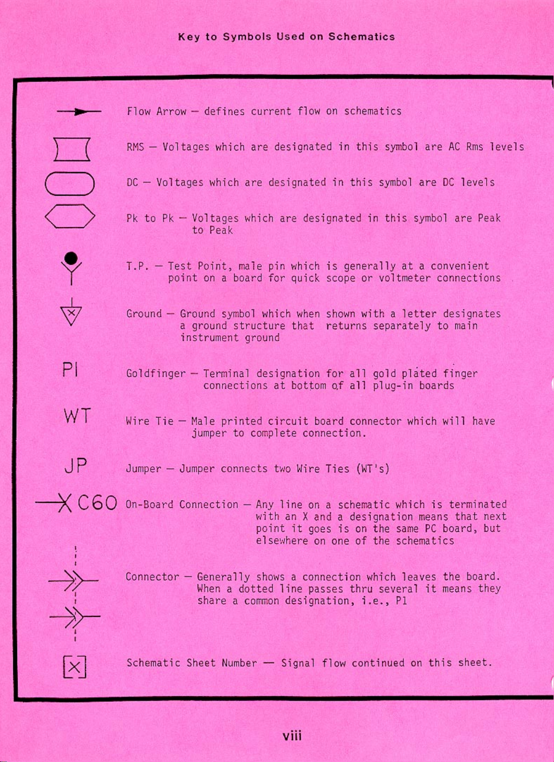
Key to Symbols Used on Schematics
Foreword
...........................
SECTION 1- PRODUCT SPECIFICATIONS
1.1
1.2
1.3
1.4
1.5
1.6
1.7
1.8
1.9
1.10
1.11
1.12
1.13
1.14
1.15
1.16
1.17
1.18
Catalog Listings
Standards
.....................
Test Stimulus
..................
..................
Output Hearing Level Controi
Signal to Noise Ratio
Tone Switch
Stimulus
Transducers
Front Panel
....................
......................
................
Controls/Rear
Power and Power Line
Battery Pack Voltage
...............
................
................
Environmental Conditions
Mechanical Dimensions
Material Used in
Leakage Test
Manufacture
....................
Headband Static Force
..............
...............
Earphone Cushion Attenuation
Accessories
....................
..............
............
Panel Connectors
..............
............
............
.....
: : 1
i
iii
vii
viii
ix
1
1
1
2
2
3"
3
3
5
5
5
6
6
6
6
6
7
-
SECTION 2
FUNCTIONAL DESCRIPTION
Figure 2-l:
2.1
2.2
2.3
2.4
2.5
SECTION 3
3.1
3.2
3.3
3.4
Front Panel Controls and Indicators
Rear Panel Connectors and Controls
General Operation of Controls
Power Up Initialization
Sleep Mode
-
ROUTINE MAINTENANCE
Earphone Cords
Hum and Random
Distortion and
Special Messages
3.4.1 CAL
3.4.2
Exx
Connectors, Controls, Indicators
........
.........
...........
..............
.....................
..................
Noise
Frequency Shift
..........
.......
..................
...
:
: :
........................
........................
. . .
iii
8
9
10
10
10
11
13
13
:
13
14
14
14
Page 4
SECTION
4- CALIBRATION
4.1
4.2
4.2.1
4.2.2
4.3
4.4
4.5
4.5.1
4.5.2
4.5.3
4.5.4
4.5.5
4.5.6
4.5.7
4.5.8
4.5.9
4.5.10
4.5.11
4.5.12
4.6
4.7
4.8
4.8.1
4.8.2
4.8.3
4.8.4
4.9
4.9.1
4.9.2
4.9.3
4.9.4
4.9.5
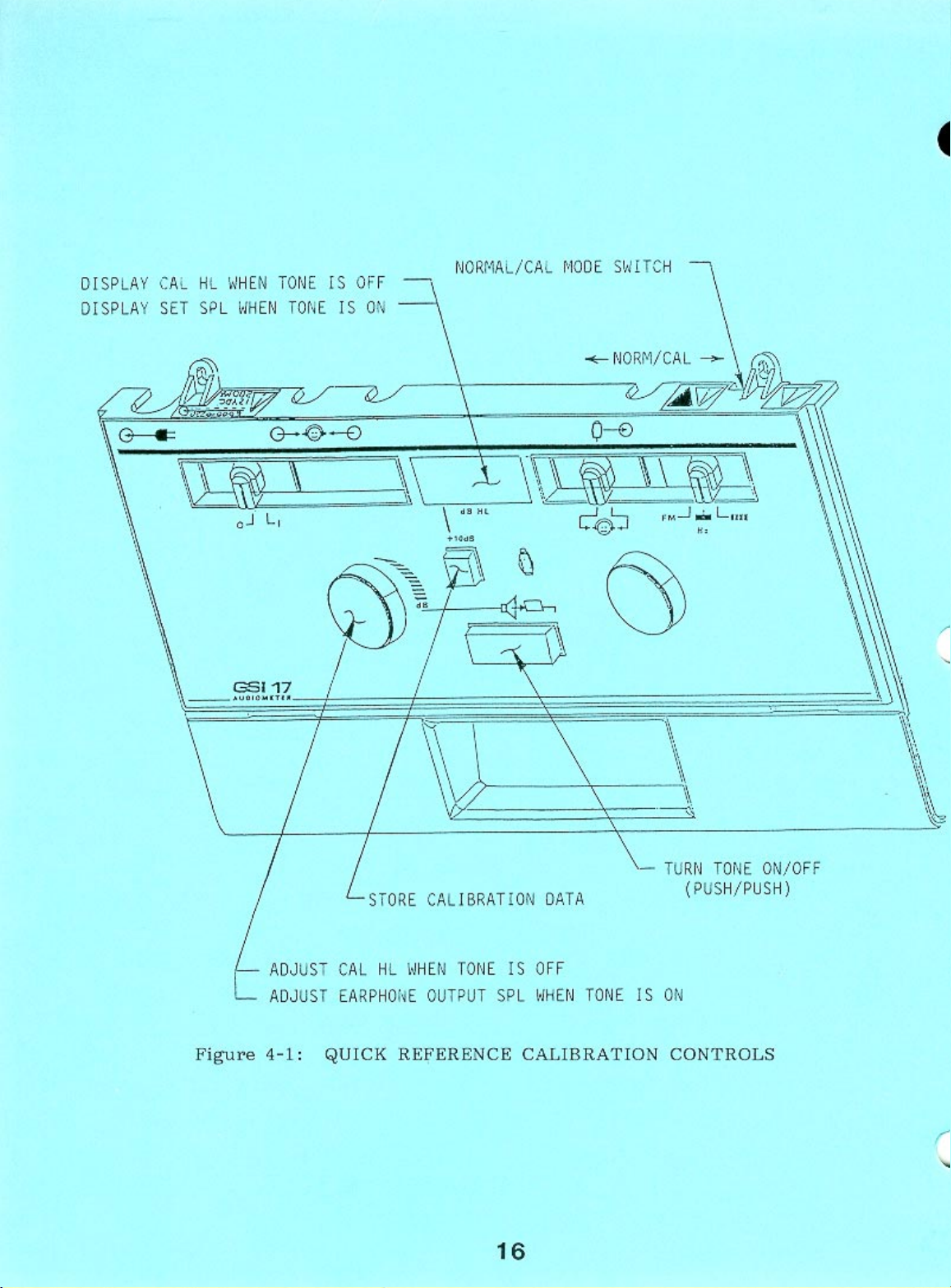
Quick Reference Calibration
Figure 4-l:
Figure 4-2:
Table 4-l:
Calibration Mode Operation
Quick Reference Calibration Control;
Access to Calibration Controls
Calibration Reference Threshold;
...........................
..........
....
....
Cal/Normal Switch
Calibration Mode Dip Switches
Calibration Mode Entry
Mode Initialization
Earphone SPL
Tone Type Switch
Calibration Mode
..................
...............
............................
............
Routing Switch
Frequency Selector'
Present Bar
HLl
Extended Range
.....................
.
...
Pushbution
Response Switch
HLDisplay
Response LED
Stimulus ON
.....................
....................
.....................
Low Battery Segment
"+"
LCD Segment
Calibration Mode Exit
Calibration Data Storage and Validation
Calibration Mode Dip Switch
Dip Switch S4
Dip Switch S3
Dip Switch S2
Dip Switch
....................
....................
....................
S1
....................
Selection of the Diagnostic Mode
Hardware Diagnostic Test (DO)
Pushbutton Diagnostic Test
..................................
................................
...................
.................
...................
................
.............
............
(D1)
.......
..........
...........
Display Diagnostic Test (D2)
A/D Converter Diagnostic Test
Attenuator Maximum Output Level Calibration
(D3) 1
(D4) .
: : 1 : 1 1 : :
16
: :
17
18
19
..
19
1
19
19
20
21
21
21
2";
22
22
22
23
23
23
23
23
23
24
24
25
25
25
27
27
28
29
31
33
34
..
38
SECTION
5
Figure 5-l:
5.1
Disassembly Instructions
5.2
5.3
SECTION
Accessories and Replacement Parts
6
6.1
Diagnostic Mode (DO)
6.2
6.3
-
DISASSEMBLY
Disassembly
Parts Numbers
-
TROUBLESHOOTING
....................
..............
..............
..........
Troubleshooting Using the Hardware
............
Figure 6-l:
Diagnostic
Functions
Output Related
Figure 6-2:
Troubleshooting
Block Diagram of Amplifier
Signal Flow
Left or Right Amplifier Troubleshooting Symptoms'
Mode
Controls and
.
..................
Symptoms
...
.......
iv
42
:3
44
45
46
48
48
49
Page 5

Page 6
Page 7

Page 8
Page 9

-
FOREWORD
GENERAL SERVICE INFORMATION
Operating,
can be found in the Instruction Manual (1717-0100).
and/or bench testing of GSI 17 Audiometers should only be
performed by trained personnel. The following instructions are
provided primarily for use by persons who are skilled in the
repair of electronic equipment.
CMOS HANDLING PRECAUTIONS
Many of the integrated circuits on the P.C. boards are CMOS and
NMOS type.
Failure to observe the following precautions whenever a circuit
board or an integrated-circuit package is handled can result in
damage to the GSI 17.
a.
b.
C.
Place instrument and parts on a grounded, conductive work
surface.
Ground yourself (with a strap having about 1 M ohm
resistance).
Ground the frame of any test instrument or soldering iron to
be used.
check-out procedures,
CAUTION
trouble-shooting hints, etc.,
Repair
d.
-
If any circuit boards are
enclose them in conductive (anti-static) envelopes.
to be stored or transported,
ix
Page 10

SECTION 1
._-
Product Specifications
1.1 CATALOG LISTINGS
1717-9700
1717-9710 GSI 17 Audiometer,
1717-9705 GSI 17 Audiometer, AC Power (Export)
1717-9715 GSI 17 Audiometer,
1.2 STANDARDS
This unit is a single channel,
It
is equipped with pure
conduction transducers (TDH39 Earphones).
ANSI S3.6 and IEC 645 Type 4 Audiometer Standards.
The GSI 17 is designed to meet current revisions of the following
standards and specifications for audiometers:
GSI 17 Audiometer, AC Power (USA)
AC Power and Battery (USA)
AC Power and Battery (Export)
pure tone screening audiometer.
tone stimulus signals, and air
This instrument meets
ANSI S3.6
IEC 645
IS0 389
IEC 601
1.3 TEST STIMULUS
PURE TONE SPECIFICATIONS
A pure tone is the only stimulus source for this audiometer.
DISCRETE FREQUENCIES
125, 250,
FREQUENCY ACCURACY
< +3%
TOTAL HARMONIC DISTORTION (FROM 125
ACOUSTICALLY)
500, 750, 1000, 1500, 2000, 3000, 4000, 6000, 8000 Hz
Frequency
125Hz
1000
3000
Hz
Hz
Test
60
dB
100
dB
100
dB
Hz TO
HL
4000 Hz, MEASURED
<2%
<
2%
<
2%
1
Page 11
1.4 OUTPUT HEARING LEVEL CONTROL
CALIBRATED IN dB
MEASURED IN INCREMENTS OF 5
HL
dB
RANGES
-10
to
125
Hz
500to
250
6000
and
Additionally A
Hz -10
8000
Hz
"+10 dB""
-10
Extended Range
maximum HL at all frequencies by 10
ACCURACY OF ALL SETTINGS
125 to 4000 Hz
6000 to 8000 Hz
1.5 SIGNAL TO NOISE RATIO (IN
>70
dB measured acoustically in dB HL
1.6 TONE SWITCH
This
electronic
switch turns the stimulus
OF
HEARING LEVEL CONTROL:
+3
+5 dB
1/3
50
to
90
to
70
dB.
dB
OCTAVE)
minimal audible distortion.
dBB
HL
dBB
HL
dBB
HL
Switch,
which
signal
extends
ON/OFF with
MODES
Normal State:
Activated State:
Stimulus OFF
Stimulus ON
RISE/FALL TIME
20-50
Measured at the -1 dB and
ms
-20
dB
points on the signal envelope.
ON/OFF RAT IO
With
the
Tone Switch OFF,
below standard reference equivalent threshold for any
the output will be at
least
1/3
-10
octave
dB
band with HL setting of 60 dB or below.
ABOVE 60 dB HL SETTING
>70
dB
CROSS CHANNEL LEAKAGE
At HL settings of 70 dB or greater,unwanted signals in the
non-
test earphone shall be at least 70 dB below the tone in the test
earphone.
dB2
Page 12

1.7 STIMULUS TYPES
Continuous Tone
Continuous FM Tone
Pulsed Tone
SIGNAL FORMAT
Continuous
Pulsed
-
Pulsed Rate:
Signal steady as long as Present Bar is depressed.
-
2.5
Pulses/sec
Pulse rate is synchronized to the "Present
first and last pulse will have 200 ms on time.
DUTY CYCLE
50%
RISE/FALLTIME
20-50 ms
ON/OFF RATIO (BETWEEN PULSES)
dB
>20
FREQUENCY MODULATION
FM Rate:
FM Deviation:
5 Hz
25%
Bar"
so that
the
1.8 TRANSDUCERS HEADSET TDH39 Earphones with 60 ohm impedance
1.9 FRONT PANEL CONTROLS AND REAR PANEL CONNECTORS
FRONT PANEL
CONTROLS
Frequency Selection
HL Select
Mode Selector (Pulsed/Steady/FM)
Routing (Left/Right)
Present Bar
Power Switch
"+10 dB"
Push-Button
3
Page 13

INDICATORS:
Power ON/OFF
Frequency Selector
dB
HL - LCD
Left/Right Earphone
Pulsed/Steady/FM
Subject
"Battery
Response - LED
Low"
(when applicable, i.e. Battery Option
purchased) - LCD
Tone ON - LED
Extended Range - LCD
REAR PANEL CONNECTORS
Left and Right Earphone -
Subject Response Switch
- 1/4"
Power Cord- 5 Pin DIN
LEFT AND RIGHT EARPHONE JACKS
Pin#
Tip
Sleeve
SUBJECT SWITCH
--Pin&
Tip
Sleeve
POWER INPUT
Function
Phone High
25 u VRMS to 2.5 VRMS
Phone Low
(J7)
Function
Switch High
Switch Low
(J1)
Battery Power
No Power
Module
Pin #
Name
--
Attached
1/4"
Phone Jack
Phone Jack
(J4 & J5)
Output Voltaqe
0 Volts
Output Voltaqe
+5
Vdc
0 Volts
Power Module
Connected
w/NiCad
Battery
Installed
Impedance
(max)
130 ohms
0 ohms
Impedance
47 K ohms
0
Power Module
Connected
w/Alkaline
Battery
Installed
ohms
Power Module
Only
No
Battery
J1-1
J1-2
Jl-3
Jl-4
J1-5
VSUP
NC
CHASGND PROTECTIVE
GND
CGND
0 (REF)
BAT/LINE 2.6 to 3.0
VBAT
+7.3
to 9.0
NC
PROTECTIVE
GND
0 (REF)
3.7 to 4.3
+7.0
All values listed are in Volts DC
to 9.0
NC
PROTECTIVE
GND
0 (REF)
3.7 to 4.3
7.0 to 13.5
t9.0 to 16.0
PROTECTIVE
GND
0 (REF)
4.3 to 5.1
+7.5
to 13.5
Page 14
1.10
POWER AND POWER LINE
_-
POWER RATING
9 Watts power module operated while simultaneously charging battery.
0.6 Watts battery power
OPERATING MODES
Power Line (Mains)
Battery- Rechargeable
(NiCad)
or Non-Rechargeable (Alkaline)
LINE (MAINS) VOLTAGE
115 V or 220 V
LINE (MAINS) VOLTAGE VARIATION
+lo%
LINE (MAINS) FREQUENCY RANGE
50-60 Hz
LINE (MAINS) FREQUENCY VARIATION
+5%
1.11
BATTERY PACK VOLTAGE
BATTERY VOLTAGE OPERATING RANGE
7.0 v to 9.0 v
BATTERY PACK TYPICAL OPERATING LIFE
NiCad:
Alkaline:
22 Hours
45 Hours
1.12 ENVIRONMENTAL CONDITIONS
OPERATING TEMPERATURE RANGE
15 to 40 Degrees Celsius
SHELF TEMPERATURE RANGE
Power Module Operated:
-40 to 60 Degrees Celsius
Battery Operated: -40 to 40 Degrees Celsius
RELATIVE HUMIDITY RANGE
5% to 90%
5
Page 15

1.13
MECHANICAL DIMENSIONS
Weight:
5.6 lbs (2.53 Kg)
Weight of Battery Pack:
Size:
13.25"W
x
14"D
x
1.5 lbs (0.68 Kg)
3.75"H
(33.66 cm x 35.56 cm x 9.53 cm)
1.14 MATERIALS USED IN MANUFACTURE
-
GSI 17 Case Assembly
-
GE Cycolac T
Battery Option Case Assembly - GE Cycolac T
Power Module Case Assembly - Noryl SE -
100J
(Flame Retardant)
1.15 LEAKAGE TEST (AC) CONNECTED/SAFETY TEST
Leakage Current High Voltage Breakdown
<25 uamps
115 V operation
220 V operation
>3000
>4000
v
v
1.16 HEADBAND STATIC FORCE
1.6 to 2.0 pounds when
earcups
are 5.7 inches
apart.
Measured
with distance center of headband to center of earphones equal to
5 inches.
1.17 EARPHONE CUSHION ATTENUATION
Frequency (Hz)
125
250
500
750
1000
1500
Attenuation
6.5
4.5
7.0
10.0
15.5
18.5
2000 26.0
3000
4000
6000
8000
30.5
33.0
27.0
24.5
6
Page 16

1.18 ACCESSORIES
Supplied Cataloq Numbers
Test Headset (TDH39)
Audiogram Forms (1 pad of 50)
Instruction Manual
Battery Pack Assembly
(used with 1717-9710,
1717-9715 models only)
8000-0175
1717-9600
1717-0100
1717-2010
AC Power Cord,one of the following:
120 v (US)
220 V (Euro plug)
240 V (UK)
220 V (Generic)
8000-0240
8000-0241
8000-0242
8000-0250
GSI 17's with serial numbers below # 0856 require a
different power module.
See Section 9, Power Module,
for details.
Optional Catalog Numbers
Response Handswitch
Patch Cord, 2 Conductor
Audiocups
Battery Pack Assembly
7874-0156
4202-0505
8000-0155
1717-2010
Battery Pack includes GSI supplied NiCad Battery.
May also be used with six
(6),
Size C, Alkaline
Batteries (not included)
Replacement NiCad Battery
8410-0060
Page 17
P
R3
R5
io
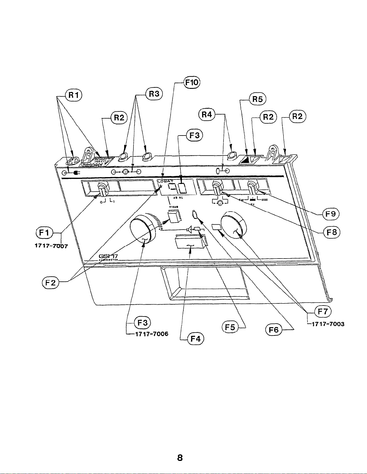
Figure 2-1:
CONNECTORS, CONTROLS, INDICATORS
8
Page 18

SECTION
2
-.
This
Connectors,
Figure
Controls,and Indicators.
2.1 THE FRONT PANEL CONTROLS AND INDICATORS (FIGURE 2-1)
section of
2-l for the layout and positioning of
F1
-
F2 - Range
F3
-
F4
-
Present Bar for stimulus presentation.
Functional Description
the Service Manual is
Controls,
Power switch and indicators for ON
increase
standard
operation is indicated by the
LCD.
HL control for setting stimulus
Level indicated on LCD.
and Indicators of the GSI 17.
extension pushbutton allows
the
stimulus intensity 10
maximum
HL at
used to
any
frequency
"+"
being lit on
intensity
describe
Refer to
all
(1)
Connectors,
and OFF (0).
operator to
dB
above
-
level.
the
the
its
the
F5
F6 - Subject response
F7 - Frequency
F8 - Routing
F9 -
F10 -
Loudspeaker
-
presentation indicated by illuminated LED.
that the test
button.
control for setting stimulus
Frequency indicated in window adjacent to control.
switch for routing the stimulus signal to
the
indicated by illustration of
Tone
type.
FM
---
Low battery indicator to alert the
the
available
depending
are used).
left or
type
= warble tone
= steady tone
= pulsed tone
batteries
switch for setting
(recharge or
on whether
in operation as such.
indicator LED shows the operator
subject
right
have a
has pressed the handswitch
earphone.
limited
replace
NiCad
or
Left or
subject.
the
alkaline
stimulus
operator
operating
batteries
Actual
frequency.
right
soon,
batteries
tone
when
time
9
Page 19

2.2 REAR PANEL CONNECTORS AND INDICATORS
R1 -
Power input
position
and rear panel indication of input
jack with front panel
indication of
power
specifications.
-
Attention,consult accompanying documents.
R2
-
Earphone output jacks with front panel
R3
indication
of left and right phone provided by illustration of
subject.
R4
Subject response switch input jack with front panel
-
indication of position.
R5
-
Calibration switch indication.
2.3 GENERAL OPERATION OF CONTROLS
All
initialization is complete,
in
depends on the HL selection. When the Extended Range is
controls
this
document and for the Extended
are
valid at
except for special cases as indicated
all
times
Range
once
the
Pushbutton
power up
which
invalid
there will be no indication given to the operator other than
absence of the
"+"
LCD segment.
the
All polled
state.
All operations of all controls are
controls are checked every 12
msec
for a
debounced
change in
for 12
msec
before processing.
The
Extended
manner.
and
hold manner (except in the Calibration and Diagnostic modes
The Present Bar and Response Switch operate
Range pushbutton operates by a push ON,
by a
push OFF
press
where the Present Bar is push ON, push OFF).
When a press and hold type control is operated all other controls
are still active.
When the operation of a control is being processed the processing
of
all
other controls is delayed until the first
operation is
completed.
2.4 POWER UP INITIALIZATION
When
the power switch is set to the ON position
the
instrument
will go through the following initialization process:
All
microprocessor
internal
and
external
hardware
components of
system will be initialized for the
the
required
type of operation.
All
LEDs
and LCD segments will be turned on to indicate that
the power up initialization is in progress.
Page 20

The RAM will be tested using a read after write verification
process.
initialized
will be displayed on the HL display and the instrument
halt.
After each location is tested its value
to 0.
If an error is detected, an
will be
error
code
will
The
generate a
stored in the EPROM.
using any of the RAM.
will be displayed on the HL display and the instrument
halt.
The operating mode of the instrument will be determined by
the position of the Cal/Normal Switch and the four Cal
Option Dip Switches. Refer to Sections 3 for the
Calibration and Diagnostic Mode initialization.
remaining initialization process will be performed for the
Normal Mode.
The
initialized to 0 HL.
be
analog hardware
selections.
After
all controls active.
2.5 SLEEP MODE
EPROM will be tested by reading the complete
current
initialized to their currently selected positions.
initialization,
EPROM to
checksum which will be compared to a
This test will be performed without
If an error is detected an error code
HL selection
All other controls and displays
will
be initialized
the instrument will remain idle
and
the
HL display
according to
checksum
will be
will
The
will
All
these
with
The GSI 17 has a mode which is designed to lengthen battery life.
When
operation
Sleep
only when the unit
available when connected to mains (ac) power.
If a period
operated (front panel, internal,
"sleep",
Prior to entering the Sleep Mode,
indicate 3 dashes ' - - -
mode status.
7 Volt) which will disable much of the analog circuitry.
the
disconnected,
a STOP state which will halt its operation.
The
either the Present Bar or power switch are toggled.
the
unit
Sleep
unit has been left on, under
for
Mode.
thus drawing minirnal current.
enters
more than 5 minutes, the GSI 17 will
It is important to emphasize that this mode
is operating with batteries, and is not
of 5 minutes has elapsed
external) the unit will go to
the display will be updated to
'I
to advise the operator of its
It will also disable the voltage converter
the
the channel will turn OFF and the CPU
Mode is exited, and normal
sleep
mode,
battery power,
since
all
transducers
operation
any control was
resumed,
without
enter the
exists
sleep
(+7
to
When
will be
will
enter
when
-
Page 21

SECTION 3
-
3.1 EARPHONE CORDS
With extended use,earphone cords tend to fray internally at
junctions with
fraying
associated
cord is flexed.
To
check
control (F7) to 1000 or 2000 Hz, set HL control (F3) at a
comfortable audible level,
earphone cord
intermittent
scratchy
the
conditions signifies that the cord should be replaced.
Repeat the test for the other earphone.
3.2 HUM AND RANDOM NOISE
will ultimately either decrease the signal level in
earphone or cause signals to be intermittent as
for
signal,
sound superimposed over the signal that coincides
flexing of the cord.
Routine Maintenance
both earphone and audiometer
either condition, set
press the Present Bar (F4)
next to plug at
abrupt
changes in
The presence of any of
the
both ends,
audiometer
signal
the
connectors. This
the
the
frequency
and
listening
level, or a
these
flex
for
with
three
This test can be made during the check for attenuator noise.
With the instrument set on 1000 Hz,
0 to 60 dB and listen for low-frequency hum (60 to 120 Hz) and
random noise (hiss or low rushing
levels.
permissible.
audible.
naive subjects and affect the accuracy of the audiogram.
Schedule the audiometer for immediate service if any of these
symptoms are detected.
3.3
DISTORTION AND FREQUENCY SHIFT
This check is most easily performed by listening to the output of
the
frequencies at
dBHL for normal ears).
Listen for rattling, rasping or distortion in the tones
presented.
change when the Frequency Selector (F5) is moved to a new
position.
other,
should be replaced. In any case,the audiometer should be
immediately scheduled for maintenance.
GSI 17
Some audible random noise at levels above 60 dB is
Below 60
Any of these noises can be confused with the signal by
through
a loud,
Listen also to ascertain that signal frequencies
If distortion is heard in one earphone but not in the
the chances are high that the earphone is at fault and
dB
however, only the signal should be
the
earphones
but not uncomfortable, level (70 to 80
move the HL control (F2) from
sound) at all attenuator
while
presenting
all 11
13
Page 22

3.4 SPECIAL MESSAGES
The
GSI 17 is a
microprocessor-controlled
performs a self check each time the instrument is turned on
self check does not occur when the instrument is "awakened"
sleep mode).
the front panel LCD if any error in the instrument
on
is detected.
Certain messages will be displayed to the
These messages are described below.
instrument
operator
operation
which
(the
from
3.4.1 CAL
When a
calibration
"CAL" will be displayed to the operator.
function at
invalid results
displayed as long as the "problem" transducer and frequency
selected.
changing either
transducer or frequency is
error
this
can be
(i.e.
frequency with this transducer, so
right earphone at 2000
recorded.
The word
If the calibration error is an
the
frequency or
the
selected
which
Hz),
has a
the
word
The audiometer will not
that no
"CAL"
will be
are
isolated
transducer
situation,
(i.e. left
earphone or 3000 Hz) will restore normal instrument function.
As is
service technician should be contacted immediately.
make
the
case with any instrument
malfunction, a
note of the combination of transducer and
certified
Remember to
frequency which
resulted in the "CAL" message.
3.4.2 Exx
When an error code consisting of an
"E"
and a 2-digit number (xx,
= number) appears on the audiometer's display, a system error has
been detected.
not
will
permit the instrument to operate.
remain on
instrument will
The GSI 17 will enter a "lockout" mode which will
the
display
shut
The specific
for
several
seconds,
itself down completely.
error
then
Should an
code
the
Exx
appear on the LCD,take the following steps:
a.
Power down,
then power up again.
This error could be
only a temporary failure and may never appear again.
However,
should the Exx message
reappear,
proceed to
steps b. and c.
b.
C.
Record the numbers that appear on the display.
Contact your certified service representative and give
them the specific numbers you have recorded.
Page 23
Page 24
Page 25
4.1 QUICK
REFERENCE
CALIBRATION
--X
a.
b.
C.
d.
Select Calibration Mode using Cal/Norm Switch.
Select Frequency and Reference HL for calibration.
Select Earphone Routing (L or R).
Turn Tone ON using Present Bar.
NOTE:
Display will update to the ANSI
proper calibration
as necessary.
e.
f.
Adjust Output Level to the required SPL using the HL Dial.
Store data using the
LCD Segment will illuminate to indicate storage of data.
g.
h
i.
NOTE:
REPLACED,
r?
w
Repeat for all frequencies.
Repeat for opposite earphone.
. .
Return Cal Switch to NORM position.
If A CAL ERROR occurs or the MICROPROCESSOR HAS BEEN
the following steps should be performed:
Short
JP1
pins 1 and 2 then power-up for 2-3 seconds.
Power-down and remove jumper.
6.6).
SPL required for
subtract or add microphone
-
+10 dB
Range Extender Pushbutton
(See Troubleshooting, Section
corrections
(+)
b.
C
(2
6
e.
Load Default Data. (See Dip Switch 4, this section).
Battery low/shut down calibration.
(See Diagnostic Mode
(D3), this section).
Attenuator maximum output level calibration.
Diagnostic Mode
(D4),
this section).
Proceed with Transducer Calibration.
17
(See
Page 26
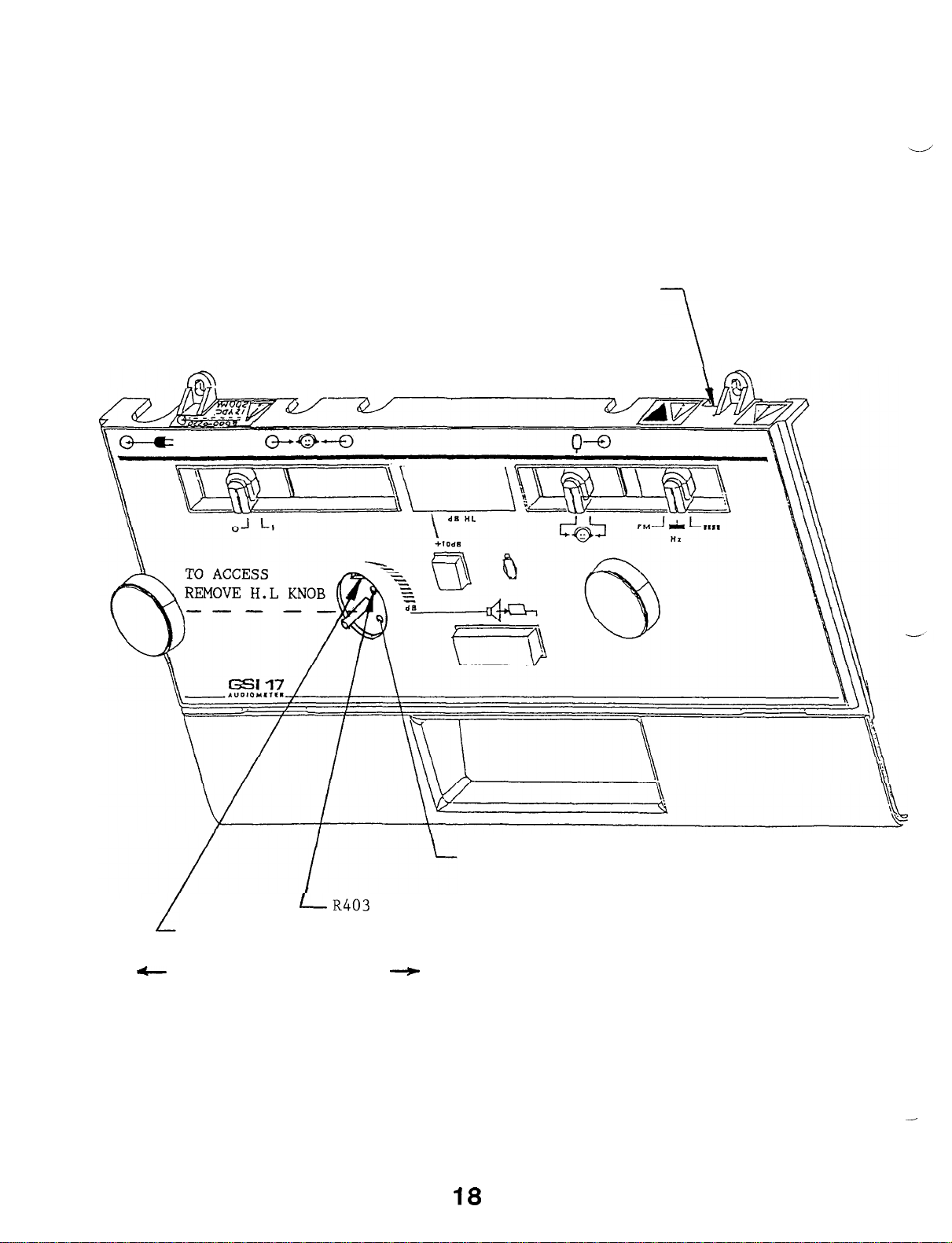
NORMAL/CAL MODE SWITCH
\
-
NORM/CAL
-
LR403
DIP SWITCH S2
(SQUARE PORT)
1
POSITION l/POSITION 4
Figure 4-2:
ACCESS TO CALIBRATION CONTROLS
R404
LINEARITY ADJUST
DISTORTION ADJUST
---t
18
-
Page 27

-
Freq
(Hz)
Table 4-l:
125 250 500
CALIBRATION REFERENCE THRESHOLDS
750
1000
1500 2000 3000
4000
6000
8000
dB 45.0 25.5 11.5 8.0
Standard Reference Threshold Levels re: 20
TDH39-P
9-A coupler.
earphones as measured on the National Bureau of Standards
Reference ANSI
7.0 6.5
S3.6-1989,
IS0 389-1975 Standards.
9.0
uPa
10.0
for
9.5
15.5
Telephonics
4.2 CALIBRATION MODE OPERATION
The
Calibration Mode is
calibration.
Normal
Mode
produce
the required SPL for the selected HL.
to determine the correct
This
used to
calibration information is used
perform
attenuator
the
transducer
during
position to
The
Calibration
the
Mode consists of two modes.
The Custom SPL Selection Mode allows the selection of
SPL values
Calibration
for
alternate
transducers.
Mode is used to calibrate the sound
The
Transducer
pressure
customized
SPL
level
(SPL) of each stimulus for each transducer.
4.2
.1
CAL/NORMAL SWITCH
This switch is used to select the operating mode of the
instrument.
switch to the CAL position while Dip Switch
position.
The Calibration Mode is entered by setting this
S1
is in the OFF
The Calibration Mode is exited by setting this switch
to the NORMAL position.
13.0
4.2.2 CALIBRATION MODE DIP SWITCHES
(See
"Calibration Mode Dip Switch In-Depth Description" later in
this section.)
These
Mode.
Dip Switches select various options of
They are read to determine the selected options when
Calibration Mode is entered.
the Calibration
the
79
Page 28

Switch
#
Function
OFF (down)
ON
(up)
(up)
s4
Default Data
OFF
Load
Loads the default Calibration
data into EEPROM when the
Calibration Mode is entered.
s3
Custom SPL Mode
GSI
Custom
Enables the selection of user
specified SPL values during
the transducer calibration
procedure when set to the
Custom position.
s2
S1
Not used
Diagnostic Mode
N/A
OFF
N/A
Selected
Selects the Calibration Mode
when the Cal/Normal Switch
is set to the Cal position
if this switch is in the OFF
position.
The status of Dip Switches #4 and #1 are read only when the
Calibration Mode is entered.
Dip Switch #3 is read and a change
in its position is processed if the Calibration Mode was entered
with this switch in the ON position.
Then the switch cay be
returned to the OFF position without exiting the Calibration
Mode.
-’
4.3 CALIBRATION MODE ENTRY The Calibration Mode can be entered via the Cal/Normal Switch at
any time except during the power up initialization phase or when
a stimulus is being presented.
In these cases the Cal Mode will
be entered when the initialization is complete or the stimulus
turned off.
The indication that the instrument is in the
Calibration Mode will be the non integer value in the format of
xx.x on the HL Display.
During the Calibration Mode initialization process all
controls
will be inactive.
When the Calibration Mode is entered,
low battery segment will be turned off.
all LCD segments except the
If Dip Switch S4 is
set
to the ON position the process of loading the default calibration
data
except
default data and checksum are being loaded.
will be started and the LCD display will have all
segments
the low battery segment turned on to indicate that the
When completed,
the
display will reinitialize to all segments except the low battery
segment will be off.
-
20
Page 29

id'
The EEPROM will then be tested by reading the complete EEPROM to
generate
in
the
flashed on
a checksum which will be compared to a checksum
EEPROM.
the HL display and the initialization
If an error is found the word
"CAL
"
process will
stored
will be
continue.
Dip Switch #3 will be checked to determine which CAL mode is to
be initialized.
If in the OFF position the transducer SPL
calibration mode is selected,and if in the ON position, the
Custom SPL selection mode will be selected.
4.4 MODE INITIALIZATION
When
the
transducer
SPL Calibration
Mode is
selected the
instrument will be initialized as follows:
Tone Type = Current selection
,=
Frequency
Current selection
Channel = OFF
Calibration HL = 10 dB below the nonextended HL limit
for.
the current transducer and frequency
Transducer SPL = Calibration HL + Current RTL
+10 dB
Pad = Out
Transducer Routing = Current selection
HL Display =Current custom SPL level stored in EEPROM
Response LED = OFF
Stimulus
On LED = OFF
Low Battery Segment = Current state
"+"
Segment = OFF
4.5 EARPHONE SPL CALIBRATION MODE
This Calibration Mode is used to calibrate the SPL for each
stimulus for each transducer.
This is done by adjusting the
selected transducer output SPL level to the specified value
displayed on the HL display.
This SPL value is the sum of the
calibration HL level and the Reference Threshold Level (RTL) for
the current transducer and frequency.
standard
RTL value or
a custom RTL
The RTL may be either the
value
depending on
the
position of Dip Switch #3 when the Calibration Mode was entered.
\_
The transducer
SPL calibration data is
stored in
EEPROM by
transducer and stimulus.
4.5
.1
TONE TYPE SWITCH
This switch
operates as in the Normal Mode to select
Type of the stimulus.
4.5.2 ROUTING SWITCH
This
switch
operates as
in the Normal
Mode to
transducer to be calibrated. All transducers must be
and they can be calibrated in any sequence.
21
the
select
Tone
the
calibrated
Page 30

4.5.3 FREQUENCY SELECTOR
This control
frequency
operates as
in the Normal
Mode to
select
to be calibrated. All frequencies must be
the
calibrated
and they can be calibrated in any sequence.
4.5.4
The
operates in
operated
PRESENT BAR
Present Bar controls the presentation of the
a push ON/push OFF manner.
If the Present
while the stimulus is off, the stimulus will be
stimulus.
Bar is
turned
It
on and remain on until the Present Bar is operated a second time.
The
stimulus will actually be turned ON or OFF when the
Present
Bar is pressed.
4.5.5
1.
HL DIAL
This control performs the dual function of selecting the HL
level at which the calibration is being performed and of
adjusting the output level of the transducer.
2.
While the stimulus is off,
Calibration HL level (Cal HL).
up by 5
dB
for each clockwise step of the selector and down
by 5 dB for each counter clockwise step.
the HL selector will select the
The level will be adjusted
For each change in
the Calibration HL level the transducer output level
(attenuator position) will be recalculated using the current
calibration data stored in the EEPROM.
the calibration HL will be from the nonextended
of
range) maximum HL limit to 20 dB below the limit.
the selector to select levels outside of this range
of
invalid.
When this occurs the level will default to the
The allowable range
(+10 dB
Operation
are
limit and the HL display will be flashed.
3.
While the stimulus is on,the HL selector (dial) will adjust
the transducer output level to allow the SPL level to be
adjusted to the required SPL level on the sound level meter.
The output level will be adjusted up by 0.5 dB for each
clockwise step of the selector and down by 0.5 dB for each
counter clockwise step. The output level is changed
according to the HL selector by directly setting the
attenuator position. Operation of the HL dial to select
positions outside of the instrument range will be invalid.
The attenuator position will be adjusted within the limits
and the displayed SPL value on the HL display will be
flashed.
4.5.6 EXTENDED RANGE PUSHBUTTON
This pushbutton is used to store the transducer SPL
data
stored,
Response LED will be turned on for 2 seconds.
data can
into
the
not be stored successfully, the word
EEPROM.
After the calibration data is
EEPROM checksum will be updated
and
If the calibration
calibration
successfully
the
"CAL"
Patient
"
will be
flashed on the HL display and the previously displayed SPL value
22
Page 31

will
can be continued for other frequencies.
4.5.7 RESPONSE SWITCH
be restored.
If this error occurs the calibration
process
This switch
Mode.
4.5.8 HL DISPLAY
a.
b.
c.
4.5.9 RESPONSE LED
This LED is used to indicate the correct storage of calibration
data in the EEPROM when the Extended Range Pushbutton is
operated.
seconds after the calibration data has been stored and verified.
If the data is not stored correctly the LED will remain off and
the word "CAL"
previously displayed transducer
restored.
Operations of the switch are not processed.
This display performsthe dual function displaying the
Calibration HL level and the SPL to which the transducer
output level must be adjusted for correct calibration.
When the stimulus is OFF,the HL display will show the
current Calibration HL level in
using digits 1, 2 and 3.
When the stimulus is ON,
required transducer output level in
xxx.x
the current Calibration HL and the Reference Threshold Level
(RTL) for the current transducer and frequency and does not
indicate correction for the sound level meter frequency
response.
using digits 1, 2, 3 and 4.
is not used during the transducer
dB
HL in the format xx.0
the HL display will show the
dB
This value is the sum of
This LED is normally OFF and will be turned ON for 2
will be flashed on the HL display and then the
output level SPL value will be
SPL Calibration
SPL in the format
4.5.10 STIMULUS ON LED
This LED is used to indicate the ON or OFF state of the stimulus.
While the stimulus is OFF the LED will be OFF and will be
ON while the stimulus is ON.
4.5.11 LOW BATTERY SEGMENT
This LCD segment will indicate a low battery voltage condition as
in the Normal Mode (ie:
4.5.12
This
Mode and will remain off.
"+"
LCD SEGMENT
segment is not used during the transducer
LOW BAT).
SPL Calibration
turned
23
Page 32

4.6 CALIBRATION MODE EXIT
The
the
calibration data is being loaded.
Calibration Mode can be exited back to the Normal
Cal/Normal
Switch at
any time
In this case the
except
for when
Calibration
Mode
default
via
Mode is exited when the loading of default data is complete.
When
initialize for the Normal Mode based on the current state of
controls,
4.7 CALIBRATION DATA STORAGE AND VALIDATION
All calibration data or other data which must be
the
the Calibration
as in the power up initialization.
instrument
is turned off is stored in
Mode is
exited
the
instrument
EEPROM.
retained
This data
will
the
when
consists of the following:
-
Transducer SPL calibration data by transducer and
frequency
-
Custom RTL values by transducer type
-
Custom RTL vs.
-
Attenuator
-
EEPROM checksum
2.5V
GSI RTL calibration selection
maximum output level limit by stimulus
The data is stored using a triple redundancy method (the same as
in the GSI 16 and GSI
data bit is stored 3 times, once in each of
within
blocks. When
location
data
This
the
EEPROM with a different format in
a specific data bit is required
in each of the 3 blocks is read and decoded.
to be valid the value from 2 of the 3 blocks
method will allow for the detection of data errors and
33
control Processor).
In this method each
3
different blocks
each of
the
appropriate
must
the
For
match.
the
the
3
correction of some errors.
If a calibration data read error is detected the frequency which
would use the data will not be available for testing in the
Normal Mode by forcing the stimulus off and not processing
operations
of the present bar.
The instrument will continue to
function and all other frequencies for which no calibration data
error
by displaying the word
exists will be available.
"CAL""
A data error will be
indicated
on the HL display until the
frequency or transducer is changed to a new selection that has no
data error.
addition to
In
individual pieces of data,
the
the
EEPROM which will allow the validity of all data
EEPROM to be determined.
the
triple redundancy validation
a 2 byte checksum will be
This check will be performed
used
for
stored in
stored in
when
the Calibration Mode is entered.
24
Page 33

4.8
CALIBRATION MODE DIP SWITCH IN-DEPTH DESCRIPTION
v
The Dip Switches,
in reverse numerical order. The reason for this is that they are
located beneath the HL dial, will be
in the order in which we anticipate the frequency of usage
described
will
be.
4.8.1 DIP SWITCH S4
IF
NOTE :
DEFAULT DATA IS LOADED, DIAGNOSTIC MODE D4 PROCEDURE
MUST BE PERFORMED!
DEFAULT CALIBRATION DATA
All calibration data or other data stored in the EEPROM will have
a corresponding set of default data stored in EEPROM which may be
used to initialize the EEPROM.
Calibration Mode with Dip Switch
This is performed by entering the
#4
in the ON position.
Transducer SPL calibration data:
This default data is typical of transducers supplied with the
instrument.
Custom RTL values:
This default data consists of the standard GSI RTL values for the
transducer types supplied with the instrument.
Custom RTL vs.
GSI RTL selection status:
This will default to the GSI RTL selection.
Attenuator 2.5 V maximum output level limit:
This will default to an attenuator limit for each stimulus.
Checksum:
The
EEPROM checksum
is calculated using the
contents of
the
EEPROM after all default data has been stored.
4.8.2 DIP SWITCH S3
CUSTOM
RTL
SELECTION MODE
This mode enables selection of the displayed custom RTL values
only and does not allow adjustment of the transducer's output
level.
If the user desires to use alternate transducers, this mode would
normally be selected first to set the custom RTL values and
the
earphone
SPL calibration would be performed.
When
Calibration Mode is entered with Dip Switch #3 in
position,
selection to
Dip Switch #3 can be used to switch from the custom SPL
the
transducer SPL mode while
remaining in
then
the
the ON
the
Calibration Mode.
25
Page 34

The
The RTL values for a left transducer and a right transducer
be the same.
in the RTL values.
MODE INITIALIZATION
custom RTL values are stored in EEPROM by transducer
The HL limits are directly affected by any
type.
changes
must
When
will be initialized as follows:
HL
The
level
down
output level (attenuator position) does not follow changes to the
custom RTL value.
The
Operation of the knob to select levels outside of this range will
not
will remain the same and will flash temporarily.
the
Tone Type= Current selection
Frequency = Current selection
Channel = Off
+10 dB
Transducer Routing
HL Display
Response LED = Off
Stimulus On LED = Off
Low
"
+
SELECTOR
HL Selector is used to select the custom
by 0.5 dB for each counter clockwise step.
allowable
be allowed.
Custom RTL selection mode is selected
Pad = Out
= Current selection
= Current RTL level stored in EEPROM
Battery Segment = Current state
II
Segment = Off
can be adjusted up by 0.5 dB for each clockwise
range of the custom RTL value is
If this occurs,the displayed custom RTL
the
RTL level.
The
+63.5
instrument
The
step
transducer
dB
and
SPL.
value
FREQUENCY SELECTOR
Selects the frequency for which the custom RTL is to be selected.
ROUTING SWITCH
Inactive in this mode.
EXTENDED RANGE PUSHBUTTON
This pushbutton is used to store the custom RTL value into
EEPROM.
checksum will be updated and the Patient Response LED will be
turned on for 2 seconds.
successfully, the word
and then the previously displayed RTL value will be restored. If
this error occurs,the calibration process may still be continued
for other frequencies.
After the RTL value is successfully stored the EEPROM
If the SPL value can not be stored
"CAL"
will be flashed on the HL display
26
Page 35

DIP
SWITCH #3 OPERATION WHILE IN CAL MODE
The
RTL calibration mode to the transducer SPL calibration mode.
OTHER CONTROLS
All
#3,
controls will not be processed.
HL
The
in
Negative values will be displayed with a minus sign.
This LCD segment indicates a low battery voltage condition as in
the Normal Mode.
PATIENT
This
successfully in the EEPROM by turning on for 2 seconds.
Cal Option Dip Switch #3 is used to switch from
other controls,
are
DISPLAY
HL display is used to display the selected custom RTL
the format
BATTERYSEGMENT
inactive
xx.x.
RESPONSE
LED indicates when the custom RTL value
except the Cal/Normal Switch and Dip
during this mode.
using digits 1 through 3 of the HL
mm
Operations of
has been stored
the
all
display.
custom
Switch
other
value
OTHER DISPLAYS
LEDs
All other
4.8.3 DIP SWITCH S2
NOT USED
4.8.4
DIAGNOSTIC MODE
The
components which
Calibration
and debugging of the board or instrument.
The
calibration mode as follows:
DIP SWITCH
-
Diagnostic
Diagnostic
Hardware Diagnostic test
Pushbutton Diagnostic test
Display Diagnostic test
A/D Diagnostic test
Attenuator Maximum Output Limit calibration
and LCD segments are not used and will remain off.
Exception when in Diagnostic Mode (Dip Switch
S1
Mode provides direct control over
Modes.
may
Mode consists of four diagnostic tests
not
This mode is provided to facilitate
be available in the Normal or
the
#1)
hardware
testing
and
one
The features of the Diagnostic Mode are controlled manually
the front panel.
from
27
Page 36

4.9 SELECTION OF THE DIAGNOSTIC MODE
CAL/NORMAL SWITCH
This
instrument.
switch
the
through #4 select the diagnostic test to be performed.
Diagnostic Mode is exited by setting the Cal/Normal switch back
to the Normal position.
When the Diagnostic Mode is entered the functions assigned to the
CAL Option Dip Switches, (except Switch
allow the selection of the desired diagnostic test.
The Dip Switches will be read only when the Calibration Mode is
+
entered.
exit
new test and then re-enter the Calibration Mode.
Switch
switch is used to
The Diagnostic
to the Cal position while Cal Option Dip Switch #1 is in
on position.
SWITCHES
To switch between diagnostic tests it is necessary to
the Calibration Mode,
#
S1
Diagnostic Mode
Enters the Diagnostic Mode when
the Cal/Normal Switch is set to
Cal.
When Dip Switch #1 is on,
Function
select
Mode is entered by setting this
reset the Dip Switches to select
the operating
Dip Switches
#1),
are redefined to
OFF (down) ON (up)
OFF
mode of
Selected
the
#2
The
the
-
s2, S3,
&
s4
DO ON
D1
ON
D2 ON OFF ON
\._*--D-
(-a
ON
ON ON
DO ON ON
DO ON ON ON
DO ON ON ON ON
xi?+
time except
selected via the switch,
the initialization is complete or the stimulus turned off.
These switches are used to
select the diagnostic test to
be performed when the Diagnostic
Mode is entered as follows:
Switch Setting Diagnostic Test
S1
s2 s3
OFF OFF
OFF
OFF ON ON
Diagnostic Mode is entered via the Cal/Normal Switch at
OFF ON
OFF
OFF ON
during the power up initialization phase. If
s4
OFF
OFF
OFF
OFF
Selected
Hardware Diagnostic
Pushbutton Diagnostic
Display Diagnostic
A/D Diagnostic
Attenuator Maximum Output Level Cal
Hardware Diagnostic
Hardware Diagnostic
Hardware Diagnostic
any
the Diagnostic Mode will be entered when
28
Page 37

When
switched
display a
selected.
into
code to
the Diagnostic Mode
indicate which diagnostic
The codes are as follows:
the
HL display
test
is being
will
"DO
"D1" =
"D2 "
I'
D3
"D4" =
The code will display for 2 seconds and then the instrument
initialize for the selected test.
= Hardware Diagnostic Test
"
Pushbutton Diagnostic Test
= Display Diagnostic Test
= A/D Diagnostic Test
"
Attenuator Maximum Output Level Cal
During this time all
will
controls
will be disabled.
4.9.1 HARDWARE DIAGNOSTIC TEST (DO)
TEST DESCRIPTION
This
diagnostic test provides direct and independent control of
the following hardware blocks:
Oscillator Frequency
Stimulus Multiplexer
Attenuator Position
+10
dB Pad Position
Transducer Routing
Each hardware block is controlled independent of all other blocks
i.e.,
selecting an
oscillator frequency will
not
change
the
attenuator position.
TEST INITIALIZATION
When switched into the hardware diagnostic test, the
will be initialized as follows:
Tone Type = Current Selection
Frequency= Current Selection
Stimulus M
UX
= Oscillator or External input based on current
frequency knob position
Channel = OFF
Attenuator position = 255
Response LED = OFF
Stimulus On LED = OFF
Low Battery Segment = Current State
II
+
II
Segment = OFF
TONE
This switch selects the Steady,
the Normal Mode.
any
used.
TYPE
SWITCH
FM or Pulsed Tone type just as in
The Steady and Pulsed Tone types will apply to
stimulus (internal
oscillator or external
The FM Tone type will always FM the internal
stimulus)
oscillator,
even if the external stimulus is selected.
instrument
being
29
Page 38

ROUTING SWITCH
This switch selects
routed just as in the Normal Mode.
FREQUENCY KNOB
The
frequency
to 8000 Hz are selected on the knob, the internal oscillator is
set for the frequency selected and the stimulus mux is set to the
internal oscillator.
between
set to
oscillator
external signal of 1 V RMS can be applied to J2 on the board.
PRESENT
The
operates in
(pressed and
be presented
a
the stimulus ON or OFF.
HL
frequency
and to control the stimulus multiplexer.
125 Hz and 8000 Hz is selected the stimulus mux will be
select
will
BAR
Present
second time.
SELECTOR
Bar controls the presentation of the
released) when the stimulus is off the stimulus will
and will remain on until the Present Bar is operated
knob is used to select
the
remain at the
a
push on/push off manner so, if it is
The
the transducer to which
the
When the unlabeled position on
external
+10 dB
pad will not be affected by
stimulus
last
selected
input.
the
internal
stimulus is
oscillator
When 125 Hz
the
The
frequency. An
stimulus.
knob
internal
It
operated
turning
u
This
position will be adjusted by
step
of the knob.
be
attenuator
flashed.
EXTENDED RANGE PUSHBUTTON
This pushbutton
pad.
selected
the pad is in.
the pad
attenuator will not be compensated for the pad position.
RESPONSE SWITCH
This
all operations will be ignored.
HL
knob is used to directly set the attenuator position.
+0.5 dB
of the knob and by
The allowable range of the attenuator position will
from 0 to 255.
position will not change and the HL display will be
When
switch is not used during the hardware diagnostic test
DISPLAY
this pushbutton is operated the
and the "+" LCD segment will turn on to
will be removed and the "+" segment
When either of these limits are
is used to control the position of the
When the pushbutton is operated a
-0.5
dB
for each counter clockwise
(1 step) for each clockwise
reached
+10 dB
pad
indicate
second
turned
+10 dB
will be
off.
The
step
the
that
time,
The
and
This display is used to display the the attenuator
the range of 0 to 255 as selected by the HL selector.
position in
30
It will be
Page 39

displayed in a right justified,
3.
integer format on digits 1, 2 and
L-
RESPONSE
LED
This LED is not used during the hardware diagnostic test and will
remain OFF.
STIMULUS
This
LED is
presented.
used to
The
LED is
indicate
when
OFF when the
the
stimulus is
stimulus is
not
being
being
presented and ON when it is being presented.
LOW
BATTERY SEGMENT
This LCD segment indicates a low battery voltage condition.
11 + 11
SEGMENT
This LCD segment indicates the position of the
the pad is "in"
the segment will be ON and when the pad is
+10 dB
pad.
When
"Out"
the segment will be OFF.
4.9.2 PUSHBUTTON DIAGNOSTIC TEST
(D1)
TEST DESCRIPTION
This
the
operated.
display the
display.
test provides a means of testing all controls,
Cal/Normal Switch,
While in this test,
keycode
This
of the new position of the control on the HL
keycode
will be displayed until another control is
for
proper
operation
the operation of any control
when
except
manually
will
for
operated.
TEST INITIALIZATION
When switched into the pushbutton diagnostic test, the instrument
will be initialized as follows:
Tone Type = Current selection
Frequency = Current selection
Stimulus M
UX
= Current position
Channel = OFF
Attenuator position = 255
+10 dB Pad = Out
Transducer Routing = None
HL Display = Displays
"D1"
for 2 seconds and then blanks
Response LED = OFF
Stimulus On LED = OFF
Low Battery Segment = Current state
II
+
II
Segment = OFF
31
Page 40

DESCRIPTION OF CONTROLS
In this test,
used to
purposes.
HL DISPLAY
This
operated.
LOW
BATTERY SEGMENT
This LCD segment will indicate a low battery voltage condition.
ALL OTHER DISPLAYS
All other
will remain OFF.
Control
Left
Right
Pulsed
FM
Steady
125 Hz
250 Hz
500 Hz
750 Hz
1000 Hz
1500 Hz
2000 Hz
3000 Hz
4000 Hz
6000 Hz
8000 Hz
Freq Position
Response Switch
Extended Range
Present Bar
HL Knob
Dip Switch
Dip Switch
Dip Switch
Dip Switch
select functions,
display
DISPLAYCODES FOR PUSHBUTTON/SWITCH SELECTIONS
Press
Release
Press
Release
the controls except the Cal/Normal Switch are
but are only operated
is used to display the
The
keycode
seqments and
#1
#2
#3
#4
will display on digits 1 and 2.
LEDs
are not used during this
Key
12
Cod
02
03
04
05
06
07
08
09
10
11
12
13
14
15
16
17
18
20
21
22
23
24
25
31
32
33
34
keycodes
e
as
for
controls
not
testing
are
test and
-
32
Page 41

4.9.3 DISPLAY DIAGNOSTIC TESTT
TEST DESCRIPTION
(D2)
This
all
"D2 "
segments and
all
inspection
test provides a means of visually testing the operation of
LCD segments and LEDS.
will
segments and
be displayed on the HL display for
LEDs
will then be blanked for 2 seconds, after which
LEDs
will be turned on for 2 seconds to
for
any displays which
When the test is selected, the
2 seconds.
do not
turn on.
code
All
allow
All
segments/LEDs will then be turned on individually for 1 second in
a
left to right,
of
any
been
shorts between segments.
sequenced through all segments/LEDs will be turned back on
top to bottom sequence to allow for inspection
After all segments/LEDs
have
to indicate the completion of the test.
During
performed
this test the low battery voltage monitoring will not be
since the display is not available to indicate a
low
battery condition.
TEST INITIALIZATION
When
switched into the display diagnostic test,
the
instrument
will be initialized as follows:
Tone Type
= Current selection
Frequency = Current selection
Stimulus M
UX
= Current position
Channel = OFF
Attenuator position = 255
+10 dB
Pad = Out
Transducer Routing = None
HL Display = Displays
"D2"
for 2 seconds and then the
display test starts
Response LED = OFF
Stimulus On LED = OFF
Low Battery Segment = Current state
'I+r'
Segment = OFF
DESCRIPTION
All controls
this
diagnostic test.
OF
CONTROLS
except the Cal/Normal switch are
ignored.
DESCRIPTION
OF
DISPLAYS
All LCD segments and
There
are
no parameter or status information displayed on
displays.
inactive
during
Operations of all other controls will be
LEDs
are tested during this diagnostic test.
33
the
Page 42

4.9.4 A/D CONVERTER DIAGNOSTIC TEST (D3)
TEST DESCRIPTION
This test will provide a means to test the A/D converter
channel
used to measure the battery voltage. When this test is selected
the A/D input will be sampled every
msec
and the converted
value
displayed on the HL display.
During
this test the low battery voltage monitoring will not be
performed since the A/D converter is not available to measure the
battery voltage.
TEST INITIALIZATION
When
switched
into
the A/D
Converter
diagnostic
test,
the
instrument will be initialized as follows:
Tone Type= Current selection
Frequency
Stimulus M
= Current selection
UX
= Current position
Channel = OFF
Attenuator Position = 255
+10 dB
Pad = Out
Transducer Routing = None
HL Display = Displays
"D1"
for 2 seconds and then blanks
Response LED = OFF
Stimulus On LED = OFF
Low Battery Segment = Current State
II
+
II
Segment = OFF
DESCRIPTION OF CONTROLS
All
controls
except the Cal/Normal switch
and
Extended
Pushbutton are inactive during this diagnostic test.
Operations
Range
of all other controls will be ignored.
EXTENDED RANGE PUSHBUTTON
This pushbutton is used to store the A/D values in the EEPROM for
"LO
Bat"
detection
"shutdown" will
occur when the battery voltage is
and
instrument
"shutdown".
too
Instrument
low to
safely operate the GSI 17 circuitry.
When the Extended Range Pushbutton is pressed the first time, the
A/D value is
EEPROM.
The Patient Response LED will be turned ON and
be displayed on
previously displayed
value can not be stored properly, the word "CAL" will be
stored as the battery low warning
the
HL display
for
2 seconds.
A/D value will be restored.
limit in the
"L1"
will
Then
If the
the
A/D
flashed
on the HL display and the previously displayed value will be
restored.
The A/D value for battery low warning limit must be
stored successfully before allowing the next press of Extended
Range Pushbutton to store the battery shutdown limit.
After the
A/D value is stored properly the EEPROM checksum will be updated.
-
34
Page 43

Page 44

Page 45

EQUIPMENT REQUIRED
Variable DC power supply,
u
minimum DVM.
1.
Adjust DC power supply to 7.5 Vdc then connect the negative
terminal to
2.
Connect DVM to Audiometer Module
TP100
and the positive terminal to
operating range of
+6.5
TP1000
Vdc to
+7.5
Vdc
TP101.
(LOW) and TP102
(HIGH).
3.
Connect simulated battery input circuit to Audiometer Module
as indicated in Figure 4-3.
4.
5.
Power up the GSI 17.
Enter Diagnostic Mode (D3).
Place Dip Switch S2 positions 1, 3, 4 to the ON
a)
position.
Place the Cal/Norm Switch to the Cal position.
b)
6.
The GSI 17 display will momentarily display D3, then will
update to a converted A/D value.
voltage to obtain 7.30 Vdc
(+50 mV)
new A/D value in memory by pressing the
Extender Button.
indicating proper
important that the
The display will momentarily display
storage of data into memory.
+10 dB
button is pressed only once. If
L2 is displayed, exit Cal Mode,
Adjust the DC power supply
on the DVM.
Store the
+10 dB
Range
L1
(It is
return to Step 5 and repeat
procedure.)
7.
Adjust the DC power supply voltage to 7.0 Vdc
Store this A/D value into memory by pressing the
(+50 mV).
+10 dB
Range Extender Button. The display will momentarily display
L2 indicating proper storage of data into memory.
8.
Adjust DC power supply to 7.5 Vdc.
positions to OFF,
and place Cal/Norm Switch S6 to the Normal
Place all Dip Switch S2
Mode position.
9.
Slowly decrease the DC power
BAT indicator is displayed.
and 7.35 Vdc.
display should blank at 6.95 to 7.05 Vdc.
Continue decreasing the input voltage.
supply voltage until the LOW
This should occur between 7.25
The
NOTE:
To clear
the LOW BA T indication the unit must be returned to full
power and the power switch toggled.
After completing calibration and verification checks remove the
power supply and simulated battery input circuit and proceed with
calibration of transducers.
37
Page 46

4.9.5 ATTENUATOR MAXIMUM OUTPUT LEVEL CALIBRATION (D4)
NOTE:
If Default
Data is loaded,
this procedure must be
performed before calibration of earphones.
TEST DISCR
IPTION
__-
If the Microprocessor of the GSI 17 has been replaced or a major
calibration data loss has occurred the Attenuator Maximum output
level must be calibrated.
When performing this calibration, the
operator will measure the output level on the connector
(important
-unloaded)
of the currently
adjust the attenuator position
measured.
repeated for
calibrated in any order,
The calibration data is then stored and the process is
all remaining stimuli.
but all must be calibrated.
until correct output voltage is
selected transducer
The stimuli may be
all output levels were adjusted to 2.5 vrms
frequency.
The newer GSI
levels for calibration.
17's
have specific maximum output
Serial numbers and output levels are
Originally
*.15
vrms for each
and
outlined below.
NOTE
When performing this procedure,
:
output must be unloaded
(no phone plugged in).
SERIAL NUMBERS LESS THAN 1230 (EXCLUDING 1068, 1175r AND 1212)
All frequencies 2.5 vrms
(+.15
vrms)
SERIAL NUMBERS GREATER THAN 1230 (INCLUDING 1230, 1068, 1175, AND 1212)
Frequency (Hz)
Voltage (rms)
125
250
500
750
1K
2
K
3
K
4
K
6 K
8
K
2.30
2.30
2.15
1.90
2.50
2.50
2.50
2.50
2.50
2.50
(2.5
dB)
_
38
Page 47

TEST INITIALIZATION
--___
When switched
into the
attenuator maximum
output
level
calibration the instrument will be initialized as follows:
Tone Type
= Current Selection
Frequency = Current Selection
Stimulus M
UX
= Oscillator Position
Channel = OFF
Attenuator Position = 255
+10 dB
Pad = Out
Transducer Routing = Current Selection
HL Display = Displays
"D4"
for 2 seconds and then
"255"
Response LED = OFF
Stimulus On LED = OFF
Low Battery Segment = Current State
"+"
Segment = OFF
TONE TYPE SWITCH
This switch
selects
the
tone
type.
The
calibration
would
normally be performed with Steady selected.
SWITCH ROUTING
-___
This switch selects the transducer.
FREQUENCY SELECTOR
This
knob selects the stimulus to be calibrated.
Its
operation
is the same as in the Normal Mode.
PRESENT BAR
---- __
The
Present Bar controls the presentation of the
operates in a
stimulus.
push ON/push OFF manner so, if it is
operated
It
(pressed and released) when the stimulus is OFF the stimulus will
be presented and will remain ON until the Present Bar is operated
second time.
a
+10 dB
pad will not be affected by
turning
The
the stimulus ON or OFF.
HL
SELECTOR
This
knob is used to directly set the attenuator position.
position is adjusted by
of the knob and by
knob.
The
allowable range of the attenuator position
from 0 to 255.
attenuator
position will not change and the HL display will be
-0.5
When either of these limits
+0.5 dB
dB
for each counter clockwise step of the
(1 step) for each clockwise
will be
are
reached
The
step
the
flashed.
39
Page 48

EXTENDED RANGE PUSHBUTTON
------
-_-
(+10 dB
PAD)
This
EEPROM.
will be
properly after 3 attempts, the word
HL and
error
pushbutton is used to store the calibration
data in
After the calibration data is stored the EEPROM checksum
updated.
then the previously displayed value restored.
occurs
the calibration may still be continued
If the calibration data can
"CAL"
will be flashed on
not
be stored
If this
for
other
stimuli.
SWITCH RESPONSE
This switch
--is not used during the
attenuator
maximum
output
level calibration and all operations will be ignored.
HL DISPLAY
----This
range of
displayed in a right justified,
display is used to display the attenuator position in
0 to 255 as selected by the HL selector. It
will be
integer format on digits 1, 2 and
3.
LED RESPONSE
This
data in
operated.
seconds after the calibration data has been stored and
LED is used to indicate the correct storage of
the
EEPROM when
the
Extended
Range
Pushbutton is
This LED is normally OFF and will be turned ON for 2
calibration
verified.
If the data is not stored correctly, the LED will remain OFF
the
word
"CAL" will be flashed on the HL display and
then
previously displayed value will be restored.
the
the
the
and
the
STIMULUS ON
LED
This LED is used to indicate stimulus presentation. The LED is
OFF when the stimulus is not being presented and on when it is
being presented.
LOW
BATTERY
SEGMENT
This LCD segment indicates a low battery voltage condition.
II + 11
SEGMENT
This LCD segment will be OFF to indicate that the position of the
+10 dB
pad is out.
40
Page 49

Page 50

Page 51

CAUTION:
USE PROPER PRECAUTIONS WHEN HANDLING AND SERVICING.
5.1 DISASSEMBLY INSTRUCTIONS
STATIC SENSITIVE DEVICES
-
12
b.
C.
d.
e.
f.
(3.
h.
i.
j.
k.
1.
Disconnect GSI 17 from power. (Battery Pack and/or Power
Module).
Disconnect and set aside all accessories.
Remove 2 round control knobs, Item 1.
Remove 3 slide switch caps, Item 2.
Close top cover, Item 3.
Turn instrument over onto its side.
Open top cover.
Remove 2 screws, Item 5,
from bottom of instrument.
Set instrument down.
Remove 2 screws, Item 6, at back of front panel.
Lift front panel and printed circuit board, Items 7 and 8,
away from bottom case, Item 4.
Remove screw, Item 9,in back of printed circuit board.
5.2 PARTS NUMBERS
ITEM
NUMBER
1
2
DESCRIPTION
HL & Frequency Knobs
Slide Switch Caps (Power, L/R,
Tone Type)
3
4
5
6
7
8
9
10
11
12
13
14
15
Top Cover (blank/no labels)
Bottom Case (blank/no labels)
#6
Screws
#6
Screws
Front Panel (blank/no labels)
Printed Circuit Board
#6
Screws
Front Panel Label
Frequency Dial
Handswitch
Power Module
Back Pack
Headset Assembly,
TDH-39P,
50 ohms
PART NUMBER
&
1717-7006
(5220-0101)
1717-7007
1717-7002
1717-7001
7044-0037
7044-0037
1717-7000
1717-4700
7044-0037
1717-0401
1717-7003 & (1717-0402)
7874-0156
(see Power Module Sec.)
(see Battery Opt. Sec.)
8000-0175
43
Page 52

5.3 ACCESSORIES & REPLACEMENT PARTS
Earphone,
Earphone Cushion, Type
Headband
Phone Cord Assembly (L and R)
Headphone Audiocups
Patch Cord, 2 Cond.
Audiogram Form, 1 pad of 50
Instruction Manual
Service Manual
Replacement
Label, Consult. Manual
Label,
TDH-39P,
NiCad
H.L. Recess
Pack
50 ohms
MX-41/AR
GSI 17
Label, Coverr
Label, Power
_
AUDIOMETER
n
Label,
601-CLASSB2
I
.
A
!
A
8000-0220
12
VDk-
I ----
l 200 MA
8000-0046 (1
8000-0143 (1
8000-0142
4204-0147
8000-0155
4204-0505
1717-9600
1717-0100
1717-0110
8410-0060
1717-0425
1717-0426
1717-0410
@
1717-0415
1717-0420
ea)
ea)
Label Adjustmentt
1717-0430
Page 53

Page 54

Page 55

DIAGNOSTIC MODE FUNCTION CONTROLS
Function controls for
-
Power Switch
F2 -
L/R Routing Switch
F3 - Tone Type Switch
F4 - HL Knob
the Diagnostic Mode DO are as follows:
Same as Normal Operating Mode
active at all times.
This 3 position switch is active at
all times in the Diagnostic Mode.
Left Position
to either
amplifiers are disabled.
Right Position
the left amplifier.
Center Position - Output is routed
to the right amplifier.
Same as Normal Operating Mode
active at all times.
The HL knob is used to control the
DAC level
indicates the current DAC level.
The DAC level range of 0 to 255
along with the
allows the operator to check the
full range of the attenuator.
voltages in the troubleshooting
section will be referenced to a
specific DAC level.
Output is not routed
-
amplifier.
-
Output is routed to
while the display
+10 dB
range extender
Both
All
-
-
F5
F6
+10 dB
-
Present Bar
-
F6A -
Stimulus on LED
F7 - Response Switch LED
Range Extender
Active at all times
ON/Push OFF selection allows the
operator to change the state of the
10 dB range extender.
of LCD indicates the Range Extender
is active.
Active at all times this Push
ON/Push OFF selection allows the
operator to turn the channel OFF and
ON.
accomplished using the attenuator.
It is important to note that the
latch is updated continuously when
the Present Bar is ON otherwise the
latch is updated only when the tone
is presented.
Same as Normal Operating Mode
indicates ON or OFF state of the
Present Bar.
In the Diagnostic Mode the
handswitch is used to ENABLE/DISABLE
the Tone Oscillator.
beneficial when measuring signal to
noise.
of the Tone Oscillator.
The channel OFF/ON is
The LED indicates the status
this Push
(+)
indicator
This is
-
F8
NOTE:
control functions (Cal/Norm Switch, Dip Switches, etc).
Frequency Selector Active at all times - same as Normal
-
Refer to Calibration Mode for more in-depth description of
Mode.
47
Page 56

6.2 OUTPUT RELATED TROUBLESHOOTING SYMPTOMS
Symptom
Output failures
Earphone Cord, Earphone, Patch
Cord/Jack Panel
Amplifier,
Possible Solution(s)
-
If applicable,
Output Routing, Amp
Enable/Disable, L/R Switch, Amp
Latch/Control Circuit.
TO
GENERAL APPROACH
If the loss of output is isolated to only one of
then
try
exchanging
FAULT ISOLATION
the earphone assemblies.
the
Plug
earphones
the
left
earphone into the right earphone jack and the right earphone into
the
earphone,
problem
assembly
defective,
tightened securely.
this
left and right earphone cords, assure that the earphone
numbers are legible,
earphones
amplifiers.
the phone
left earphone jack.
then the problem is internal to the Audiometer.
remains
is at fault.
with the original earphone, then
If the earphone assembly is found to be
first check the set screws and assure that
If the screws are loose a problem similar to
would result.
If the screws are secure try exchanging
if not mark the earphones accordingly.
are
calibrated
If the problem shifts to the opposite earphone
cord is defective.
If the problem shifts to
specifically to the
If the problem
left
remains
the
the
opposite
earphone
they
and right
with
If the
are
the
serial
The
then
the
original earphone then the earphone is defective.
-
CIRCUIT ANALYSIS FAULT ISOLATION
Refer to Audiometer Board Schematic
AT-I-EN UATOR
#3,
Section 8.
Figure 6-2:
BLOCK DIAGRAM OF AMPLIFIER SIGNAL FLOW
48
Page 57

L
6.3 LEFT OR RIGHT AMPLIFIER TROUBLESHOOTING SYMPTOMS
(Refer to Figure 6-2:
ALL VOLTAGES MEASURED WITH THE CHANNEL ON,
ACCORDINGLY, 1
kHz
FREQUENCY, OUTPUT LOADED.
BLOCK DIAGRAM OF AMPLIFIER SIGNAL FLOW)
L OR R SELECTED
Check for signal presence/absences at the amplifier output pin
U4 00
pin 5 - Right
U4 01
pin 5 - Left
This should be an undistorted
sinewave
of approximately 80
mvRMS.
Removing the earphone (load) should cause the output level to
increase significantly.
If the
possible
signal is present here, but not at the
that
the
phone jack is at fault or an
connection is missing.
as
necessary.
If the signal is not present
Perform point-to-point connection
earphone it is
artwork etch
checks
here,
check
the
amplifier input pin
U4 00
pin 3 - Right
U401
pin 3 - Left
This input level should be an undistorted
approximately 80
mvRMS.
If the input signal is present here but
sinewave
of
not present at the amplifier output pin then the amplifier may be
defective.
U4 00
U401
for a
amplifier
present then verify that the +5 Vdc and
present.
okay,
the amplifier is most likely defective.
First check the amplifier enable line
pin 1 - Right
pin 1 - Left
logic 0
for
(-5 Vdc). A logic 1
muting
or to conserve power.
(+5
Vdc) disables the
If a
logic
-5 Vdc power supplies are
If amplifier enable line and power supplies check
0 is
out
If a logic 0 (-5 Vdc) is not present at the amplifier enable line
then check
U507
pin 16 - Right
U507
pin 19 - Left
for a logic 1
or
U403
Left could be defective.
(+5
Vdc).
If a logic 1 is present then
Check the power supply lines
U402
Right
accordingly.
NOTE:
U403.
lines
then
The
Remove
U507
U402
or
U507
latch output may be loaded by a defective
U402
or
U403
respectfully, then recheck the control
pins 16 and 19.
U403
is defective.
If these voltages are
This type of error occurs
now
U402
or
correct
quite
frequently with CMOS.
49
Page 58

CPU
LATCH
l-l510
V
REF
CI RCU\T
L1302
L
V
D/A
- CON’JWI’W. -
u303
OSC.OUT
x
u302
00X
ATTE
u301
UNEARIN
ADIllS
u300
UJuAToR
EC,
-
-
3
ROUTIM$
Figure 6-3:
BLOCK DIAGRAM OF ATTENUATOR SIGNAL FLOW
6.4 ATTENUATOR TROUBLESHOOTING HINTS
(Refer to Figure 6-3:
Non linearity, no output,
The VCA
(U301)
output is controlled by a dc voltage produced by
the D/A converter
controlled by the processor via the latch
BLOCK DIAGRAM OF ATTENUATOR SIGNAL FLOW)
large shifts in output level.
(U303)
The input to the
(U501).
D/A
converter is
If the
from the attenuator circuit is not present at the output
circuit check the following.
NOTE:
Assure
Calibration data is used to update the
that the
calibration data is appropriate or
latch circuit.
Diagnostic Mode DO.
In Diagnostic Mode DO the display will indicate a DAC
255 all bits at the latch output should equal +5 Vdc
attenuator
clockwise
should
be at max attenuation.
Turning the HL
should cause the DAC value to decrease and the
value of
and the
level to increase. At a DAC value of 0 the latch outputs
all be
attenuation/maximum
when the Tone Bar is ON,
low
and the
gain.
otherwise the latch is updated only when
output
should be at
(The latch is updated continuously
the tone is presented).
output
routing
select
knob
output
should
minimum
50
Page 59

L
Use
the
following table to check various circuit
proper level.
voltages
for
NOTE:
Table 6-l:
Voltage measurements with DAC value of 0, 1
ATTENUATOR CIRCUIT TEST CHECK
kHz
Frequency
and Tone Steady.
Measurement Location
Junction R314 & R316 (R Side) - Osc. out
-
U3033
Pin
DACVoltageReference
15
Expected Voltaqe
.2
VRMS
3.35Vdc
Tone OFF
0
0
1.2
0 Vdc
Vdc
Vdc
VRMS
U3033Pins
U3022Pin
U3000Pin
U3000Pin
thru
4
7
7
1
Junction R313 &
11
+55
-3.4
+
.5
0
R311 (R
Side) -3.4 Vdc
Vdc
Vdc
Vdc
-.155Vdc
VRMS
10 dB Range Extender Check
U3000Pin
1
DAC
DAC
=
0
=
10
Pad OUT
1.2
VRMS
.7
VRMS
Pad In
*
3.5
2.1
VRMS
VRMS
* Sine Wave should have "clipping" evident on negative and
positive slopes.
Increasing DAC value to 5, 6, or 7 should
decrease output level and eliminate clipping.
51
Page 60

6.5 OSCILLATOR TROUBLESHOOTING HINTS
As a
rule
representatives
circuitry is
troubleshoot in the field using a DVM.
may be checked at specific
output pins may be checked for "relative" output level. In
the
only
test
equipment
carried by
is a Digital Volt Meter (DVM).
generally
difficult, if
not
Various power supply pins
IC's
on the oscillator
service
The
oscillator
impossible to
circuit
and
this
instance relative refers to an estimated voltage output dependent
on the
frequency
circuitry measures its input signal.
5
0 Vdc to
should measure
Vdc square wave with a
2.5
indicate steady state output.
2.5
VRS would be normal and an ac reading of 0 V would
steady
the
state.
This type of information allows us to
presence or absence of signal flow.
can sometimes point to open connections,
switches,
or other hardware failures.
selected and the speed at
Generally when measuring a
Vdc.
50/50
A measurement of >4 Vdc
duty cycle the dc voltage
Likewise an ac RMS measurement of
Using this information
defective amplifiers and
which
or<1
Vdc
the
DVM's
would
indicate
check
for
The most effective way to troubleshoot the oscillator is with an
oscilloscope.
sinewave
or square wave.
The ocsilloscope enables visualization of the
Distortion or frequency errors become
obvious and signal level may be observed at the same time.
The
#1.
via
routes
circuit.
filtered (BP),
The
oscillator circuit is located on the Analog Board
The oscillator output is routed to the attenuator
the
Filter
the
appropriate
Multiplexer (U 200).
signal to the input of
The
Filter
the
Multiplexer
attenuator
This signal is either the oscillator output Band
Low Pass filtered (LP), or a test
antialliasing filters round the edges of
signal
the
square
Schematic
circuitry
Pass
input.
wave
clock input prior to filtering.
-
If the oscillator circuit is non-functional verify that the square
wave clock signal is present at
(2.5 VRMS)
indicated
filter
on the front panel.
U203
square
pin -7 should be a square wave with
wave
which should be the
and its voltage swing should be approximately -3.5 V to
(2.5 VRMS).
be a clean undistorted
+5
Vdc (2.5 VRMS).
The output of the Switched Capacitor filter
sinewave
6.6 TROUBLESHOOTING THE PROCESSOR
U511 -
The output of
pin 10.
same
the
This is a
frequency as
antialliasing
O-5
Vdc
rounded edges
+3.5
Vdc
should
with a voltage swing of -5 Vdc to
(U503)
There are some processor related problems that can be repaired in
the field.
combination device.
converter,
and a free running timer.
associated as lock-ups.
The processor on the audiometer board is a
It has its own internal EEPROM, D/A
RAM, watch dog circuitry,
Priority Interrupt function,
Processor errors are generally
Lock-ups occur for various reasons. A
multi-
shorted or loaded address or data line will stop the processors
execution process, the result is a 'lock-up'.
When this occurs
the processor will generally continue to strobe the address and
52
Page 61

i,
data lines.
In this instance probe these lines with an
oscilloscope and look for any address or data lines that are in-
active (no data or periodic state transition).
If an in-active
line is found the processor may be at fault but the problem is
most likely a bad port or latch somewhere on the
bus.
This type
of hardware failure generally requires replacement of the
Audiometer Board,as this is probably the most cost effective way
to resolve this type of problem.
A lock-up may also occur as the result of a defective EPROM
(U505).
processor to execute.
may pause or get "LOST".
This EPROM contains all the instructions for the
If there are no instructions the processor
This type of failure very seldom occurs
as these EPROMS are very stable devices.
When a new processor is
may lock-up.
There are internal system configuration registers
that must be loaded by shorting
the processor to ground) prior to power-up.
installed into the audiometer board it
JP1
pins 1 and 2 (Mode B pin 2 of
After power-up wait
for a period of (2 or 3 seconds) then power the unit down and
remove the jumper.
The operator/technician should then load
default data and perform self calibration (refer to Section 4,
Calibration).
It is important to note that this problem could
also occur if a data error was present in the EEPROM portion of
the processor.
6.7 POWER SUPPLY RELATED PROBLEMS
The GSI 17 is powered by battery or by the Power Module (Battery
Eliminator/AC Adapter).
defective,
first check the power source.
replaced? Were the batteries new?
eliminator functioning properly?
connector which attaches to the GSI
When a power supply is suspected to be
Have the batteries been
Dated?
Is the power
Is there 13 V present at the
17?
When these questions
have been answered then proceed with troubleshooting on the
Audiometer Board.
the positive terminal of
Check the positive
Check for the presence of 7 Vdc to 13 Vdc at
C101
(use
terminal of
TP100
C100
for ground reference).
for +5 Vdc.
Check the
negative terminal of Cl03 for -5 Vdc.
NOTE:
If any power supply voltage is incorrect the problem may
be the result of a short or load somewhere on the line.
It
is best to try lifting the regulator output pin
the
output is
lifted pin prior to replacing the device.
correct with the pin lifted, check
If the
the power
and
measure
regulator
supply
capacitors for low impedance or a shorted device.
If the operating life of the batteries appears diminished,the low
battery indicator may be improperly calibrated or the GSI 17 is
drawing excessive current. Refer to
Section 4,
Calibration, for
the battery calibration procedure.
53
Page 62

The current draw of the GSI 17 can be checked by connecting an
ammeter in place of the power switch.
active mode should be less than 75 ma. In the sleep mode the
current draw should be reduced to approximately 16 ma.
6.8 TROUBLESHOOTING THE DISPLAY
Refer to the Calibration Mode, Section 4, for method of entry
into the Display Diagnostic Mode
(D2).
The current draw in the
The LCD Display is relatively easy to troubleshoot.
for the Display
approximately 36 Hz (28 ms) with a
segments of the LCD have a commonconnection via BP1 and BP2.
This Back Plane (BP) is driven continuously with a 36 Hz square
the same frequency that the segments are driven at.
segments to be
square wave which is
square wave.
are driven with a square wave that is 0
Back Plane.
in phase there is no potential across the segment and the segment
is OFF.
potential present a all times and the segment is ON.
if a segment is missing an AC meter can be used to check for
proper phase relative to the Back Plane.
V would indicate the signals are out of phase and that the
segments should be illuminated.
indicate that
relative to ground should indicate 2.5 VRMS.
the presence of a square wave.
Vdc would indicate steady state or a possible open connection.
With this information it should be relatively easy to establish
if the driver or LCD segment is at fault.
When the two signals are out of phase there is 5 V
(U501)
illuminated (black) they must be driven with a
Any segments which are not
When the two signals present at the LCD segment are
the
sources each segment with a square wave of
180'
signals are
out of phase relative to the Back Plane
50/50
An ac measurement of 0 V would
in phase.
A dc measurement of 0 Vdc or 5
duty cycle.
oing to be illuminated
8
or in phase with the
An AC measurement of 5
An ac measurement
This would indicate
The driver
All
For the
Generally,
6.9 SWITCH RELATED FAILURES
Refer to the Calibration Mode, Section 4, for method of entry
into Pushbutton Diagnostic Mode
test can be used in troubleshooting all the front panel switches
and dip switches independent of their Normal Mode functions. It
should be relatively easy to isolate switch failures using this
mode.
D
The Pushbutton Diagnostic
54
Page 63

6.10 ERROR MESSAGES
L
The GSI 17 will display a Diagnostic
Error Message should a
condition exist which may cause incorrect or unreliable operation
If
of the instrument.
an error is detected normal operation of
the instrument will be aborted and the instrument will stop
operating.
operator by displaying an abort code on digits
HL Display.
"Exx"
where xx is a 2 digit abort number to identify the type of
The condition of the error will be indicated to the
1,
2, and 3 of the
The error message will be displayed in the format of
abort.
When a system error
operation,
If the channel i s
1.
2.
3.
All transducers will be disconnected from the channel.
The Watch Dog (COP) timer and clock monitor will be
the following will occur:
occurs which causes the instrument to halt
"ON"
it will be turned OFF.
disabled.
A
*
.
5.
The HL dispiay will display the error code.
The CPU will be put into a state which will halt its
operation and not allow it to resume unless the power is
cycled.
The system error conditions
as follows:
Error Code
E01
Probable Cause
EPROM FAILURE
.-
-
error at power up. If not recoverable replace
U505
replacing
open traces,
then
U503
U505
or
or shorted traces between
U503.
to be tested for and their codes are
and Solution
Indicates the EPROM checksum was in
If the problem is not resolved by
U503
then check for Buss loading,
U505
and
E02
E03
E04
E05
E06
_
RAM FAILURE
WATCH DOG TIMER ERROR
-
If not recoverable replace
If not recoverable replace
-
U503.
U503
-
CPU CLOCK FAILURE
If not recoverable replace
U503.
UNDEFINED INTERRUPT ERROR - If not recoverable
replace
OPCODE TRAP ERROR
then
U503
U505.
then
U505.
-
If not recoverable replace
U503
54A
Page 64

Error Code
--
Probable Cause and Solution
--
E07
E08
E09
E10
E11
INVALID TONE SWITCH SETTING - If not recoverable
replace S5 then
INVALID FREQUENCY SWITCH SETTING - If not
recoverable replace RE2 then
INVALID ROUTING SWITCH SETTING - If not recoverable
replace S4 then
UNDEFINED KEY CODE ERROR
with the failure of any front panel control. If
not recoverable replace
CONFIGURATION REGISTER ERROR - The processors
internal registers are not properly configured.
With the power switch OFF install a temporary
jumper wire (short) across
place the power switch in the ON position and wait
for approximately 10 seconds.
registers should now be properly configured.
Return the power switch to the OFF position and
remove the jumper wire.
exists replace the processor
above procedure.
U503.
U503.
U503.
This error may occur
-
U503
then
JP1
If the problem still
U505.
pins 1 and 2.
The processor's
U503
and repeat
u
Then
the
El2
E20
E21
E22
E23
E24
LOW VOLTAGE ERROR
adjustment is not set to within the acceptable
range.
Down Calibration (Calibration Section 4.9.4). If
the problem still exists replace
procedure.
CALIBRATION DATA READ ERROR - If not recoverable
replace
HL LIMIT EXCEEDED
U503.
INVALID EXTENDED RANGE SELECTION - If not
recoverable the problem may be related to
U506, U508
CALIBRATION DATA WRITE ERROR - Should occur only in
the Calibration Mode.
recoverable replace
INVALID PRESENT BAR DUE TO CALIBRATION ERROR
Should occur only in the Calibration Mode.
recoverable replace
If not recoverable perform Battery Low/Shut
U503.
NOTE:
or
NOTE:
-
Re-cal may clear.
U503.
U503.
U503.
Battery Low/Shut Down
-
U503
and repeat
Re-cal may clear.
If not recoverable replace
U509,
If failure is not
If not
-
E25
ERROR PERTAINS TO FACTORY CALIBRATION PORT
recoverable replace
U503.
54B
-
If not
Page 65

Error Code
--
Probable Cause and Solution
E26
E27
E28 & E29
E31
E32
E33
EEPROM CHECKSUM ERROR
is in error. If not recoverable perform
calibration. If the problem is not resolved by
calibration replace
EPROM TO EEPROM DATA LOAD ERROR - If not
recoverable replace
CALIBRATION TYPE READ ERROR - Should occur only
upon entry to Calibration Mode.
the problem may be related to
U506,
BATTERY SHUT DOWN LEVEL READ ERROR - If not
recoverable perform Battery Low/Shut Down
Calibration (Calibration Section 4.9.4).
problem persists replace
BATTERY WARNING LEVEL READ ERROR - If not
recoverable perform Battery Low/Shut Down
Calibration (Calibration Section 4.9.4). If
problem persists replace
STACK OVERFLOW ERROR - Should always be
recoverable.
U505.
or
U503.
If the error persists replace
-
U503.
U503
then
Data in the Mirror Memory
U505.
If not recoverable
S2, S6, U509, U508,
If the
U503.
U503.
U503
or
E34
E35
E36
E37
E38
E39
BAD POINTER TO EEPROM ROUTINES - If not recoverable
replace
INVALID KEY CODE ERROR
U505
then
INVALID KEY SOURCE ERROR - If not recoverable
replace
INVALID QUEUE POINTER ERROR - If not recoverable
replace
BATTERY VALUE OUT OF RANGE - If not recoverable
perform Battery Low/Shut Down Calibration
(Calibration Section 4.9.4).
replace
ERROR PERTAINS TO FACTORY CALIBRATION PORT
recoverable replace
U505
U503.
U505
U505
U503.
then
then
then
U503.
U503.
U503.
U503.
-
If not recoverable replace
If problem persists
-
If not
54c
Page 66

Page 67

Page 68

7.1 ANALOG CIRCUIT
A square wave at the desired frequency is generated by a
internal
to the microprocessor.
This square wave is applied to
timer
the input of switched capacitor filters for smoothing into a sine
wave.
frequencies
Since
The filter
except
section is programmed as Low
8
KHz where it is configured for
Pass
there are two filter output configurations, a
for
Band
all
Pass.
multiplexer
(switch) is used to route the sine wave to the attenuator block.
The
resolution
DAC,
Normal
used only for calibration purposes in the Calibration Mode.
total
required to
attenuator
by an 8 bit Digital to Analog Converter
is a voltage controlled amplifier set to
.5 dB
(DAC).
which is processor driven, controls the attenuator in
Mode at a resolution of 5.0
dynamic range of the attenuator is 112
provide
the Normal Mode HL range as
dB.
The.5 dB resolution is
dB.
This range is
well as
The
the
The
the
overhead dB range required for calibration per frequency.
Following
Range extension is accomplished by increasing the gain of the
Amp,
which is
the
sourced
attenuator
by the attenuator, by 10
is a
=10 dB
range
dB.
extension
block.
OP-
The range extender circuit applies the pure tone sine wave to the
input of
signal
is
never
power amplifiers, in turn,
the output routing switches.
The switches
apply
the
to either the left or right power amplifier, however, it
applied to both simultaneously.
The
left and
right
drive the left and right earphones.
7.2 DIGITAL CIRCUIT
The
microcomputer.
power consumption.
bit programmable I/O ports,
(A/D),
Counter/Timer,
very few external
external EPROM
heart of
the
digital
circuitry is a MC
68HC11A1
This CPU was chosen for its flexibility and
Functions available from the device are (5) 8
an 8 bit analog to digital
8
K Bytes of ROM, 256 Bytes of RAM, 512 Bytes of EEPROM,
and Serial Port Interface.
support devices required.
As a result, there are
If there is an
(32 K Bytes), a programmable
converter
timer,
low
and
miscellaneous decodes, line multiplex, etc.
The
instructions
conjunction
pertinent
parameters
clock
instructions,
In
analog
CPU executes the commands stored in ROM and
are
with
the
result of a
front
panel
look-up tables, and such,
for
calibration data for the selected parameters.
could be:
frequencies for the switched capacitor
HL calibration for a
specific
filters,
or as simple as an ON/OFF command to a CMOS switch.
summary,
and
the digital circuitry in the GSI
17 controls
display circuitry in such a manner
EPROM.
command in
applying
frequency,
that
the
These
the
Such
display
the
front
panel selections are processed and acted upon accordingly.
57
Page 69

Page 70

8.1 GENERAL NOTES
._
a.
The Audiometer Board is a self-contained audiometric module.
If the board is changed,
the headphones must be calibrated
to the board.
b.
If during the calibration process,
default data is loaded
then diagnostic mode D5 procedure must be performed (see
Section 4, Calibration of this manual).
C.
If the micro controller or audiometer board is changed then
default data,
and Diagnostic Mode D5 procedure must be
performed.
8.2 MICROCOMPUTER
The
MC68HC11A1
is an 8 bit MCU with sophisticated on-chip
(U503)
peripheral capabilities. In the GSI 17's application it operates
at a nominal 1 MHz bus speed.
smaller size and higher speeds with the low.power and high
immunity of
CMOS.
On-chip memory
The HCMOS technology used combines
noise
includes
512 bytes of
electrically erasable programmable ROM (EEPROM) and 256 bytes of
random-access
memory (RAM).
The on-chip peripheral
functions
include:
-
Eight channel analog to digital (A/D) converter with eight
bit resolution of which two channels (PE6 and PE7) are used
to monitor battery functions.
-
Free-running timer system that has three input capture
lines.
Two lines
(PAO
and
PA1)
are used to decode HL
direction and amount of change on an edge triggered basis.
The third input capture line (PA2) is used to detect left
right output selection.
vs.
-
A real time interrupt function (XIRQ) which is used by the
Present Bar for immediate processing of a "Present" command.
-
Self-monitoring circuitry is
against system errors.
This
included on-chip to protect
"computer operating properly"
(COP) watch dog system protects against software failures.
The internal 512 byte EEPROM contains data for the A/D
relative
battery level below usable level threshold.
or
to the
"LO
BAT"
(Low Battery) threshold and
Also
converter
"DEAD BAT"
stored in
the EEPROM are all calibration HL, SPL and attenuator data.
data is
method
each calibration point per frequency is stored
stored
with a triple redundancy
technique. In
3 times,
61
This
this
Page 71

once in
calibration point is requested,
of the
valid
calibration error is detected,
each of 3 different blocks within the EEPROM.
the appropriate location in
three blocks is read and decoded.
the
value
from 2 of the 3 blocks must
For the data to be
match.
the frequency and transducer which
When a
each
If a
would use the data will not be available for testing by virtue of
the
function for
channel being forced off.
all combinations of
which have valid calibration data.
The instrument will
frequencies and transducers
This memory retains its
continue to
data
even when power is not applied to the device.
-
The
capacity.
functions as adding HL dial to transducer RTL for a given
setting.
internal 256 bytes of RAM is used in a
It's
used
as a temporary storage
medium for
This memory can only retain data when it
"scratch-pad"
such
output
has power
applied to it.
8.3 EPROM
The
32
K byte by 8 bit EPROM contains the operating
for
the GSI
and executes the instructions accordingly.
U505)
17.
instructions
The microcomputer fetches data from
The instructions
the
EPROM
for
the Normal calibration and diagnostic modes are contained in this
memory.
EPROM is non-volatile memory, meaning that data
storage
is not lost when power is removed from the device.
8.4 TIMER
There is a programmable timer chip which is used for 3
functions
(U511)
via 3 programmable outputs.
different
One output is the
square
wave (SQWIN) which ultimately gets filtered into the pure tone
used for presentation into the earphones.
clock (SCFCLK)
points.
output
selected.
These first two outputs (SQWIN, SCFCLK)
frequencies dependent upon the
The third output is a set pulse train which
negative-going .2 used pulse every 2
for setting the switched capacitor filter
msec
pulses are used as an interrupt for the processor so that it
update
the COP circuit and perform the polling of the status of
A second output is the
3
dB
have
front panel
variable
frequency
sends a
to
the CPU.
These
can
the controls not previously mentioned.
8.5 POLLED CONTROLS
The majority of controls are read via a polling technique.
is,
determined rates of time.
at a rate of 12 msec.
status,
status
stated
bounce time (settling time) every 12 msec.
the
CPU reads
the status of
each
key/control at
The polling in the GSI 17 takes
then
12
msec
Every 12
if that control is determined to be in
later,
it is acted upon.
msec
a control is "looked
Therefore it
that the following controls are polled and allowed a
The keys/controls
the same
That
pre-
place
at"
for
can be
de-
as follows:
The HL Knob
The Frequency Dial
The
=10 dB
Extended Range Key
62
are
-
Page 72

The Left/Right Control
The FM/Pulsed/Steady Control
The Subject Response Switch
The Calibration/Normal Mode Switch
The Calibration/Diagnostic Mode Dip Switch(s)
8.6 INPUT/OUTPUT (I/O) PORT DESIGNATIONS
Physical Signal
Port
Bit
Name
Direction
Description
U503
PORT(A)
0
2
3
4
5
6
7
HL1
HL2
LEFT
SPARE
SPARE
+10 dB
SPARE OUT
UNUSED
IN
IN
IN
N/A
N/A
OUT
IN
HL1
and HL2 form a 2 bit
code of the HL selector
position.
HL2
Position 1 - 1
Position 2 - 1
Position 3 - 0
Position 4 - 0
LEFT and UNUSED form the 2
bit code of the Routing
Switch position.
UNUSED LEFT
Invalid - 0
Unused - 0
Right - 1
Left
Not Used
Not Used
+10 dB
Pad control. 0 = Pad Out
Not Used
See Bit 2 - LEFT
(Extended Range)
-1
HL1
1
0
0
1
0
1
0
1
1 = Pad In
(Range
Extended)
U503
PORT(E) 3
FREQ1
2
1
0
FREQ2
FREQ3
FREQ4
IN
IN
IN
IN
SELECT FREQ FREQ4 FREQ3 FREQ2
12525
Hz
250
Hz-
500
Hz-
750
Hz-
1
KHz-
1.5KHz-
2
KHz-
3
KHz-
4
KHz-
6
KHz-
8
KHz-
Pos.12-
FREQ1-FREQ4
code of the Frequency
Selector position.
LSB
1
1 1 1 0
1
1 1
1
1
1
1
0 0
0 0 1 0
0 0 0
0
form the 4 bit
1
1 0 0
0 0
0
0
0
0 0
1 1
0
0 0
1 0
1 1
1 1
63
MSB
FREQ1
1
1
0
1
Page 73

Physical
Port
Bit Name
Signal
Direction
Description
U503
PORT(E) 4
U503
PORT(D) 6
U503
PORT(D) 0
PULSE
5
FM
IN
IN
PULSE and FM form the 2
bit code of the Tone Type
switch position.
PULSE
0
;
1
BAT/LINE
IN
FM
Invalid - 0
FM
Pulsed
-0
-
1
Steady - 1
Voltage Source Status
0=lINE
Voltage
l=Battery Voltage
7
BATVOLT
IN
Analog Battery Voltage
input to the A/D converter
RXD
1
2
3
4
TXD
MISO
MISI
SCK
IN
OUT
IN
OUT
OUT
SCI Received Data
SCI Transmitted Data
SPI Input - Not Used
SPI Data to Display Driver
SPI Clock to Display
Driver
5
SLEEP
OUT
Sleep Mode Status
O=Awake
1+In
Sleep Mode
6
7
N/A
N/A
N/A
N/A
U509
0
1
2
3
4
5
6
DIAG
SPARE
ALTREF
DEFAULT
RANGEX
SUBRES
CAL
IN
IN
IN
IN
IN
IN
IN
Dip Switch #1 -
Diag/Cal
Mode
O=ON =Enter Diag Mode
l=OFF=Enter Cal Mode
Dip Switch #2 - Spare
Dip Switch #3
-GSI/User
SPL
O=ON
1=OFF=GSI
=User
SPL Mode
SPL Mode
Dip Switch #4 - Default
Data
O=ON
1+OFF=Do
=Load
Default Data
Not Load Data
Extended Range Switch
Status
0=Pressed
1=Relaesed
Subject Response Switch
Status
0=Pressed
1=Released
Cal/Normal Mode Switch
Status
O=Calibration Mode
l=Normal Mode
64
Page 74

Physical
Port
-
j3&
7
Signal
Name Direction Description
PRESENT
IN
Present Bar Status
0=Pressed
1=Released
07
0
1
2
3
4
5
6
7
AFILHI
50/100
BP/LP
EXTIN
PRESLED
SUBLED
RON
LON
OUT
OUT
OUT
OUT
OUT
OUT
OUT
OUT
Oscillator Antialiasing
Filter Select
AFILHI
125 Hz - 0 0
250 Hz
- 0 0
500 Hz - 0
750 Hz - 0
1 KHz
1.5KHz 2 KHz
3 KHz
-
1 0 0
1
-
1
-
1 0 0
50/100 BP/LP
0
0
0 0
0
0
0 0
0 0
4 KHz -1 1 0
6 KHz
-
1
1
0
8 KHz -- 1 1 1
Oscillator Clock Scale
Select (see AFILHI for
States)
Oscillator Digital Filter
Type Select (see AFILHI
for States)
External Input MUX control
0=Select
1=Select
External Input.
Oscillator
Channel ON LED Control
0=LED
1=LED
OFF
ON
Response LED Control
0=LED
1=LED
OFF
ON
Right Channel Routing
Control
0=Channel
1=Channel
OFF
ON
Left Channel Routing
Control
O=Channel OFF
l=Channel ON
u510
DACO
DAC1
DAC2
DAC3
DAC4
DAC5
DAC6
DAC7
OUT
OUT
OUT
OUT
OUT
OUT
OUT
OUT
65
Attenuator DAC
Level
Control. 0 ->255
Page 75

U511
Timer
Signal
Name Direction Description
TMRO
TMR1 SCFCLK
TMR2
Front
Panel/
Freq
125
250
500
750 909.09 90,909
1000 1176.47 117,647 34.00
1500 1818.18
2000 2500.00
3000 3333.33
4000 5000.00
6000
8000 8000.00
Filter
Cutoff
Freq
150.38
300.75
606.06 60,606
8000.00 400,000
SQWIN
CLKGEN
SWITCHED CAPACITOR FILTER CONTROLS
Switched
Capacitor
SCFCLK (Clock)
Freq
15,038
30,075
181,818
250,000
333,333
250,000
400,000
OUT
OUT Clock.
OUT
Timer
Setting
266.00
133.00
10.00
10.00
8254 Counter 0 Used for
the Oscillator SWQIN
Stimulus Frequency 8254
Counter 1 Used for the
Oscillator Switched
Capacitor Filter SCFCLK.
(see the following table
8254 Counter 2 Used to
Produce the 2
base.
50/100
State
66.00
44.00
22.00
16.00
12.00
16.00
Frequency =
msec Time-
Antialiasing
AAFIL
State
0
0
0
0
0
0
0
0
1
1
1
BP/
LP
0
0
0
0
1
1
1
1
1
1
0
0
0
0
0
0
0
0
0
0
1
-1
8.7 DISPLAY (LCD)
The LCD is a reflective
is the largest indicator on the GSI 17, and it is used for a
variety of purposes.
possible error messages in the Normal Mode, along with SPL and
A/D numbers in the calibration and Diagnostic Modes.
each mode's functional description for detail).
An LCD segment is energized only when there is a 5 Volt potential
across it.
drive signal,
signal and CH2 to the segment drive signal.
the
across it.
signals should be out of phase, therefore applying
To confirm if a segment is receiving the
connect
3-1/2
Some purposes are:
CH1
digit Liquid Crystal Display. It
of an oscilloscope to
indication of HL and
(Refer to
appropriate
the
For an
backplane
"ON"
5 Volts
segment
6666
Page 76

8.8 OUTPUT ROUTING AND POWER AMPLIFIERS
Analog
and possibly range extended,
amplifiers.
switches
The
U402
and
U403
CPU reads
are used to route the
attenuated,
signal to the left and right
the
status of
the
front
power
panel
left/right switch and controls the analog switches accordingly.
The
ability to
cross-channel
approximately 1 watt,
This is a very important feature for use under battery power.
series
use of
two power amplifiers
turn
them off (Pin 1) minimized
leakage.
The
amplifiers,
(U400, U401)
which
as
the
can be turned off for minimal current draw.
130 ohm resistor at their output serves as an
well as
the
potential of
can
deliver
A
attenuator
for both signal and noise when the 60 ohm phones are connected.
8.9 POWER SUPPLY
The on-board power supplies consist of a +5 Volt regulator, -5
Volt regulator and a voltage converter.
whether it be from a battery or
approximately +7 Vdc.
+5
U102,
Volt regulator.
analog and digital circuits.
applied to converter
circuitry,
is inverted to -7 Volts.
This positive voltage is applied to the
The positive 5 Volts supplies both the
The unregulated +7 Volts is also
U101
where,
a battery eliminator, is
through its switched capacitor
The unregulated negative
voltage is then applied to the -5 Volt regulator
The input supply,
U100.
Note that
the voltage converter is disabled (shutdown) whenever the sleep
mode is entered.
through
U202.
This is accomplished via controls switched
8.10 OSCILLATOR
The
oscillator is
comprised of the following
IC's
and
their
functions:
U203 -
U202 U201 -
U200
U203
takes
front panel selected frequency and converts it to a +5 V
This
signal is
antialiasing
eliminate high freqeuncy harmonics.
applied to
level shifter
antialiasing filter
programmable switched capacitor filter
-
Low Pass/Band Pass selector
the 0 to 5 Volt sqaure wave (from
then applied to the
filter
"rounds"
the edges of
antialiasing
The
output of this filter is
the input of switched capacitor
U511.10)
the sine
filter
at
the
signal.
filter. An
wave to
U201.
The
switched capacitor filter is programmed via clock frequencies and
the
state of the
50/100
line.
found at the end of the I/O port designation listing (see
U201
(from
U507
controls can be
U507).
The switched capacitor filter is set to a Low Pass configuration
for
all frequencies except 8 KHz where it is set for Band
Pass.
This filter reduces harmonics and any other noises resulting in
a clean sine wave product.
67
Page 77

8.11 ATTENUATOR AND 10 dB RANGE EXTENDER
The attenuator
(U301)
is a voltage controlled amplifier.
Although it does have amplification gain, the majority of its
dynamic range is used as an attenuator.
The total range of the
attenuator is 112 dB which is adjustable using a variable dc
voltage applied to Pin 3 (EC) of the device.
operating mode,the attenuator is set to 5 dB resolution.
calibration mode,
however,
0.5 dB resolution is available and
In the normal
In the
made possible by an 8 bit digital-to-analog converter (DAC).
Earphone calibration is accomplished by storing an HL to SPL
value per frequency in a look-up table in EEPROM.
For example,
at 1 KHz and 80 dB HL the CPU will set the attenuator to a
dB
position which will establish 87
Therefore,it can be stated,
that the attenuator for a given
SPL in either earphone.
frequency is offset from the nominal indicated HL by a decibel
value equal to the Reference Threshold Value
resolution of
The
switchable
amplifier
feedback resistor. This stage serves as the
dB.
stage
(U300)
following the attenuator has a
range extender circuit used during normal operation.
the stage is changed by switching Resistor R304 in parallel
R303
or grounding R304 at one end
(+10 dB
position).
(RTV) to a
+10 dB
The gain of
with
8.12 POTENTIOMETER ADJUSTMENT PROCEDURES
d
L
LINEARITY ADJUST
I
a.
Set front panel controls to: 1 KHz, 80 HL, Tone Steady,
()
Channel ON.
b.
Set a reference on Sound Level Meter (SLM) with either left
or right earphone coupled to it.
C.
d.
e.
Reduce HL dial to 60 HL and note reading on SLM.
Adjust R404 for a
obtained in step
-20 dB change from the reference level
"b".
Re-check 80 HL for 20 dB change,
II. DISTORTION ADJUST (R403)
NOTE:
TP100
a.
b.
Tone may be locked
"ON" in the Normal Mode by connecting
to the cathode of CR3.
Set front panel controls to:
activated),
Tone Steady, Channel ON.
Connect a distortion analyzer to either left or right phone
output,
load with 60 ohms and select the appropriate output
using the front panel switch.
readjust R404 as necessary.
1 KHz,90 HL
(+10 dB
_*
68
Page 78

C.
Adjust R403 for minimum distortion.
should be less than 2% (THD).
Minimum distortion
L
d.
Check distortion at opposite earphone jack.
NOTE :
2%,
remove 60 ohm load and recheck.
If distortion at output cannot be adjusted to
amplifiers may be at fault, if not,
8.13 SUGGESTED REPAIR PARTS
1717-4700ROT
Audiometer Board Rotating Stock
1717-9610 Parts Kit
Note:
Qty
3
1
1
1
1
1
1
2
1
1
The following parts are included in this kit.
GSI Part Number Description
7874-0173
7874-0172
7874-0171
7874-0175
7874-0170
5437-1275
1717-3810
4214-0155
4204-0147
1717-9610-AS
Slide Switch (Power, L/R, Tone Type)
HL Switch
Frequency Switch
Cal/Norm Switch
4 Position Dip Switch
LCD
LCD Fixture
Phone Jacks
Earphone Cord
1717 LCD Installation
Procedure/Parts Kit
If distortion
less
reduces, power
than
attenuator may be the cause.
69
Page 79

Page 80

Page 81

Page 82

Page 83

Page 84

Page 85

8.14 AUDIOMETER BOARD PARTS LIST
1717-2700 (3)
\-_
Ref Designation Description
INTEGRATED CIRCUITS
U100
U101
U102
U200
U201
U202
U203
U300
U301
U302
U303
U400 and
U402
and
U401
U403
U500
U501
U503
U504
U506
U507
U508
U509
U510
U511
IC, Lin.,
IC,
LT105A,
IC, Lin.,
IC,
MC14052B,
MF10,,
IC,
IC,
MC14053B,
MC79L05,
Volt. Converter/Reg.
LM2931, +5V
Dual Filter
IC, LT1013, Dual Op. Amp.
See
U203
IC, DBX2155, VC Amp.
See
U203
IC, AD7523,
IC, MC34119, Low Pwr. Audio. Amp.
See
U202
IC,
IC,
IC,
IC,
IC,
IC,
IC,
IC,
See
IC,
MC34064,
H0438A,
MC68HC11A1,
74HC00,
74HC138,
74HC273,
74HC373,
74HC244,
U507
82C54,
Undervoltage Sensor
Serial LCD Driver
Quad. 2 Input Nand.
1 of 8 Decode/Demux
Octal D Flip Flop
Tri State Octal Latch
Octal Buffer/Driver
Prog. Timer
-5V Reg.
Reg.
Dual Chan. Mltplx.
Tri 2 Chan. Mux/Demux
8 Bit D/A Conv.
8 Bit
MicroContr.
Part No.
5432-1151
5432-1152
5432-1150
5431-7027
5432-1091
5431-7054
5432-1050
5432-1092
5432-7003
5432-1120
5432-1117
5433-1020
5431-9017
5431-3000
5431-3138
5431-3273
5431-3373
5431-3244
5431-9012
DIODES
CR1 and CR2
CR3
CR5
CR100*
CR101
CR102
CR500
RESISTORS AND POTENTIOMETERS
R100*
R200
R201
R202
R203
R204
R205
R206
R207
R208
and R209
R210
R211
R300
LED, HLMP-0504, Green, Square
Diode,
See CR3
Diode, Zener,
Diode,
Diode,
See CR3
Res., Film,
Res., Film,
Res., Film,
See R200
Res., Film,
See R200
Res., Film,
Res., Film,
See R200
Res., Film,
Res., Film,
See R200
Res., Film,
1N4151
1N4004
1N5817
SA11A
10 Ohm,
10K, 1/4W,
1/4W,
1%
3.57K, 1/4W,
4.22K, 1/4W,
30.1K,
1/4W,
10.7K, 1/4W,
6.19K, 1/4W,
200K, 1/4W,
1%
39.2K, 1/4W,
1%
1%
1%
1%
1%
1%
1%
6084-1206
6082-1001
6083-1100
6081-1002
6084-1017
6350-9100
6350-2100
6350-1357
6350-1422
6350-2301
6350-2107
6350-1619
6350-3200
6350-2392
*See Section 9, Power Module for update.
77
Page 86

Ref.
Desiqnatio
n
Description
Part No.
RESISTORS
R301
R302
R303
R304
R305
R306
R307
R308
R309
R310
R311
R312
R313
R314
R315
R316
R317
R400
and R401
R402
R403
R404
R500
R501
R502
R503
R504
R505
and R506
R507
R508
R509
and
R511
R512
R515
thru R517
AND
POTENTIOMETERS
R510
Res., Film,
Res., Film,
Res., Film,
Res., Film,
Res., Film,
Res., Film,
Res., Film,
5.23K, 1/4W,
49.9 Ohm,
20K, 1/4W,
9.09K, 1/4W,
3930 PPM,
4.02K 1/4W,
150 Ohm,
See R302
Res., Film,
Res., Film,
Res., Film,
See
R303
Res., Film,
Res., Film,
100 Ohm,
49.9K, 1/4W,
27.4K, 1/4W,
3.32K, 1/4W,
1K, 1/4W,
See R300
See R304
Res., Film,
Res., Film,
90.9K, 1/4W,
130 Ohm,
See R200
Pot., Comp.,
Pot., Comp.,
See R200
See
R314
Res., Film,
See
R314
332 Ohm,
Res., Comp.,
See R314
Res., Film,
499 Ohm,
Res., Comp.,
See R310
Res., Film,
24.3K, 1/4W,
See R314
See R502
1%
1/4W,
1/4W,
1%
1/4W,
50K, 20%,
1K, 10%,
25 Turn
25 Turn
1/4W,
47K,
5%
1/4W,
10M, 1/4W,
1%
1/4W,
1%
1.0K,
1%
1%
1%
1%
1%
1%
1
1%
1%
1%
1%
1%
1%
5%
5
6350-1523
6350-9499
6350-2200
6350-1909
6700-0002
6350-1402
6350-0150
6350-0100
6350-2499
6350-2274
6350-1332
6350-1100
6350-2909
6350-0130
6049-0350
6049-0500
6350-0332
6099-3475
6350-0499
6099-6105
6350-2243
RPSOO
RP501
RP502
RP503
RP504
RP505
CAPACITORS
Cl00
C101
C102
C103
C104
C105
C106
C200
and
C201
Res.,
Res.,
Network, 47K x 9,
Network,
10K
x 9,
See RPSOO
See
RP501
See RPSOO
Res.,
Cap., Tant.,
Cap., Tant., 4.7
Cap., Cer., 0.1
Cap.,
Cap., Cer.,
Network,
47
Elect.,
4.7
.01 uF, -20%, +80%, 50V
100K
x 8,
uF 20%,
uF, 20%, 50V
uF, 20%, 50V
uF,
208,
Cap., Tant., 100 uF, 16V
Cap., Tant., 10
See
C104
uF,
208, 6v
78
+2%
22%
+2%
16V
10V
6740-1747
6740-1712
6740-1710
4450-4520
4450-4990
4400-3000
4450-4700
4400-3003
4450-4515
4450-5100
Page 87

Ref. Desiqnation Description
Part No.
\_
CAPACITORS
C202
and
C204
C205
C206
C207
C208
thru
C211
C300
and
C302
C303
C304
and
C306
C307
thru
C311
C400
thru
C404
and
C406
and
C408
and
C410
C411
C412
C500
C501
thru
C505
C506
C507
C508
C510
C511
thru C517
C518
c519
C203
C210
C301
C305
C310
C403
C405
C407
C409
C503
See
C102
Cap., Cer.,
Cap., Cer.,
Cap., Cer.,
Cap., Cer.,
See
C102
See
C205
See
C102
.0047 Uf, 5%,
.001 uF, 5%,
.01 uF, 20%,
0.047
Cap., Cer., 68
Cap., Cer.,
See
C103
Cap.,
See
See
See
See
See
See
See
See
See
Cer.,
C102
C306
C104
C102
C104
C102
C104
C306
C104
1.0
0.47
Cap., Cer., 47
See
C104
See
C102
Cap., Cer., 22
Cap., Cer., 10
See
C102
See
C1303
See
C102
See
C303
See
C205
50V
50V
50v
uF, 5%,
50V
pF, 10%, 100V
uF, +20%, -80%, 50V
uF,
-20%
+80%,
5ov
pF, 10%, 100V
pF, 10%, 100V
pF, 10%, 100V
4400-3010
4400-3008
4400-3004
4400-3009
4400-3007
4400-3002
4400-3001
4400-3006
4400-2022
4400-3005
IC
SOCKETS
XU503
XU505
MISCELLANEOUS
J1
J4 and J5
J7
J8
LCD1
RE1
RE2
s2
s3
S6
Socket,IC, 28 Contact
Socket, PLCC., 52 Contact
Conn.,
Jack,
See
Pow. Input, 5 Pin, Din Socket
Earphone & Handswitch, PC
Mtg.
J4
Conn., 6 Pin, Female, Telephone
Display,
HL Encoder,
LCD, 3.5 Digit
2-Bit Rotary
Frequency Encoder, 4-Bit Rotary
Switch Dip, 4 Position
Switch,
Switch,
Present/Ext.
Cal/Norm,
Range Switch
DPDT, Rt. Angle
7540-1828
7540-1852
4230-4025
4214-0155
4230-4030
5437-1275
7874-0172
7874-0171
7874-0170
1717-0400
7874-0175
79
Page 88

Ref. Desisnation
MISCELLANEOUS
Description
Part No.
No.
SHIELD 1
SHIELD 2
SHIELD 3
TP100
U505
Y500
DBL Pole, 3 Pos.
thru TP102
ESD Director, LCD,
ESD Director, LCD, 0.83" H.
ESD Shield, Switch,
Jumper,
EPROM, Programmed
Crystal, 4 MHz, Low Profile
Switch,
Steady/Pulse)
Spacer, LED
Insulator, Crystal
Test Point
Slide (ON/OFF, L/R, FM/
.83"
.45"
H.
H.
1717-8005
1717-8005
1717-8010
5080-0001
1717-0500
5075-0045
7874-0173
7574-0205
7574-0210
80
Page 89

Page 90

Page 91

Page 92

Page 93

Page 94

10.1 DESCRIPTION
The GSI 17 can be operated via battery power with the 1717-2010
battery option.
supplied rechargeable
available size C alkaline batteries.
illustration of the battery pack).
This battery pack can be used with the
NiCad
pack (8410-0060) or with commercially
NOTE:
(See Figure
10-3
GSI-
for an
In no
affect instrument calibration.
10.2 BATTERY PACK INSTALLATION
If your
pack is already installed in the instrument and you can disregard
this section.
If the GSI 17 battery pack has been purchased separately from the
audiometer,
-
there are four (4) screws included with your battery pack option.
They will be used to mount the pack into the storage cavity of
the audiometer.
close to one side, are four
sections of the case which must be punctured to provide entry
holes for the four screws.
Before installing the battery pack,
turned off and unplugged from the AC power (mains) outlet.
Unplug the power cord,
used) from the back panel of the audiometer.
from the instrument.
cover and place the instrument on a flat surface. Proceed as
follows:
audiometer was purchased with the battery
it must be installed into the instrument.
instance will loss of
On the bottom of the storage cavity, located
(4) indentations.
(See Figure 10-l).
the earphone jacks and the handswitch (if
For greatest convenience, remove the top
battery power
option,
Note that
These are thin
be sure the instrument is
Remove these items
the
a.b.Using a Phillips head screw driver, gently apply
pressure to the four indentations, one at a time, to
puncture the case for the screw entry holes.
the screw driver will help achieve the correct hole
size.
Turn the instrument on its side.
pack,
while inserting the mounting screws.
screws.
you will need to hold it in the storage cavity
To attach the battery
Secure all four
Turning
87
Page 95

Figure
10-2 :
BATTERY POWER CONNECTION
88
Page 96

C.
Connect the battery pack power cord (A) to the power
cord receptacle on
the rear panel of the audiometer.
For line power operation (mains) or recharging, connect
the instrument power cord (B) to the receptacle on the
lower edge of the battery pack (perpendicular to the
instrument rear panel).
(See Figure 10-2).
10.3 NiCad BATTERY OPERATION
The GSI 17 battery option is supplied with an installed,
rechargeable NiCad battery pack.
fully charge,
operation.
and will provide about 22 hours of continuous
The green LED on the pack itself will be lit when
It requires about 18 hours to
charging is in progress. The words LO BAT will be illuminated on
the front panel LCD when the battery charge is getting low so the
operator will know when to recharge the batteries.
is lit,
the instrument will operate (continuously) for about two
When LO BAT
hours before it shuts down completely.
NOTE:
In no instance will loss of battery power
affect instrument calibration.
CAUTION:
Although no damage to the rechargeable NiCad
batteries will occur if the pack is left
charging for more than the 18 hours required
for a full charge,
left charging for extended periods
the batteries should not be
(i.e.
several days) because the useful life of the
rechargeable NiCad pack will be shortened.
Lucas GSI recommends unplugging the battery
pack power input cord from the rear of the
audiometer and plugging the main line power
cord into this jack if main line power is to
be used most of the time.
save battery life,
To
which
the
operation.
audiometer will
The
operator will know the instrument is
because the LCD will show three dash lines (-
the GSI 17 has a special "Sleep
shut down after
5 minutes of no
-
-).
Mode" in
"asleep"
To "wake
the instrument the operator only needs to press the Present
There is no danger of presenting a loud tone to the test
when the instrument
the
audiometer is
"wakes up""
awake.
automatically resets its output to 0
If the GSI 17 is operated until the battery charge
below an
acceptable
function at all.
The display will be blank except for the LO BAT
voltage level,
because no tone is presented until
In
addition,
the
dBHL.
has
the
instrument
subject
instrument
dropped
will
up"
Bar.
not
89
Page 97

indication,
operation,
(full charge),
If the audiometer is operated via AC power (mains) with the
rechargeable batteries in place,
occur.
10.4 ALKALINE BATTERY INSTALLATION/OPERATION
and the controls will not function.
the batteries must be recharged for
or AC power (mains) may be used.
some battery charging will
To restore
up to 18 hours
For
recharging
batteries
These
operation.
The
batteries as it does for the NiCad batteries, that is, the
LO BAT will be lit on the LCD when there are about 6 hours of
continuous battery operation available.
mode" also
useful life.
Before installing the alkaline batteries, unplug the GSI 17 from
the line power (mains).
remove the battery pack cover by removing the two screws that
hold it in place, then lift off the cover.
NiCad batteries out of the pack (they are wrapped in plastic and
will come out of the pack as a single unit).
disconnect the lead wires of the NiCad batteries from the battery
compartment by disconnecting the small plug connector.
notice six spring mounts on the top and bottom of the battery
compartment.
10-3
longer,
batteries
low voltage indicator works the same way for
for a pictorial diagram of NiCad removal).
continuous battery operation, such as
on a regular basis is not possible, the
can
be replaced with six size C
will
works with the alkaline batteries to
These are for the alkaline batteries.
provide about
To install the alkaline batteries, first
45 hours of
alkaline
In addition, the
Carefully pull the
periods when
rechargeable
batteries.
continuous
the
prolong their
alkaline
words
"sleep
Carefully
You will
(See Figure
Before inserting the alkaline batteries into the pack, check the
label on the bottom surface of the compartment which indicates
the correct polarity (orientation) of the batteries.
batteries in,
the label.
positioned with the spring mounts touching the batteries.
is only one way the cover fits correctly so that the screws are
secure.
If alkaline batteries are not going to be used
on a regular basis,
in the audiometer.
from the battery pack and stored in a cool,
dry place.
one at a time,
Replace the battery pack cover being sure it is
matching the polarity (+ or -) with
NOTE:
they should not be stored
They should be removed
Put the six
There
90
Page 98

\
v
7044-0037
Figure 10-3:
NiCad
17 17-0406
BATTERY OPERATION
9’1
Page 99

10.5 NiCad BATTERY ASSEMBLY PARTS LIST 1717-2010
Description
Base,
Cover,
Label,
Assembly,
Screw,
Screw,Pan Hd.,
Battery
Battery
Battery Compartment
Battery Charge Board
Locking 6-32 x
6-32 x
.375
.750
lg.
lg.
Battery Pack, GSI 17, NiCad
Assembly,
(Not Replaceable -
Assembly,NiCad Conn.,
(Not Replaceable -
10.6 BATTERY BOARD FUNCTIONAL DESCRIPTION
Battery Contact Board, Top
Swaged)
Battery Contact Board
Swaged)
The Battery Charger Board serves several purposes.
Part No.
1717-7004
1717-7005
1717-0442
1717-4710
7044-0037
7044-1205
8410-0060
1717-0405
1717-2015
When
connected to the GSI 17 the charger board relay connects the
battery voltage to the GSI 17 power input. When a power module
is connected to the Battery ChargerBoard the applied voltage
energizes
the relay which connects the charger board regulated
voltage to the GSI 17 power input. The charger board voltage
regulator U1 (LM2931) is capable of sourcing 150 ma which is used
to power the GSI 17 and charge the NiCad Battery if installed. A
resistive divider network on the board enables the GSI 17 A/D
converter to determine if the GSI 17 is being powered by battery
or via the power module.
-
92
Page 100

 Loading...