

Page 1
M-Series Wall Mount Kit for Welch Allyn Propaq CS EMP Monitor
The purpose of this guide is to:
1. Describe installation of the Wall Mount Kit and mounting of monitor and power supply.
2. Describe adjustment of tilt and tilt tension.
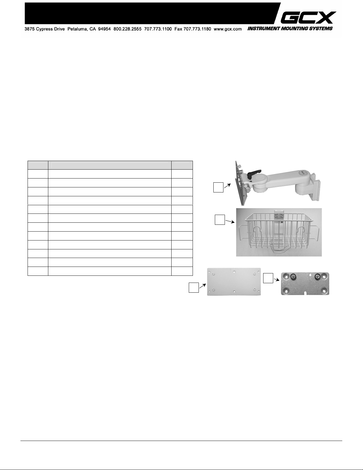
Parts Reference
The following parts and hardware are included in this installation kit (hardware not shown):
Installation Guide
Item # Description Qty
1 Wall Channel, 19'' (includes hardware and instructions) 1
2 Utility Basket, Channel Mount 1
3 Adjustable Stop 1
4 M-Series Arm, 8'' 1
5 Sub Plate 1
6 #6-32 x 3'' Pan Head Machine Screw (PHMS) 4
7 Mounting Adapter 1
8 #8-32 x 1/4'' Pan Head Machine Screw (PHMS) 4
9 #8 x .030 Flat Washer 4
10 1/8'' Hex Wrench 1
11 5/32'' Hex Wrench 1
12 Channel Cover (includes instruction) 1
Tools Required: Phillips screwdriver (not provided), 1/8'' and 5/32'' hex wrenches (provided), and 1/2'' [13mm] socket
wrench or nut driver (not provided).
Installing the Wall Mount Kit
4
2
5
7
1. Install Wall Channel in accordance with GCX Wall Channel Installation Instructions (DU-WC-0002).
DU-PR-0013-06 Rev A 2/28/07 GCX Corp Page 1 of 5
Page 2
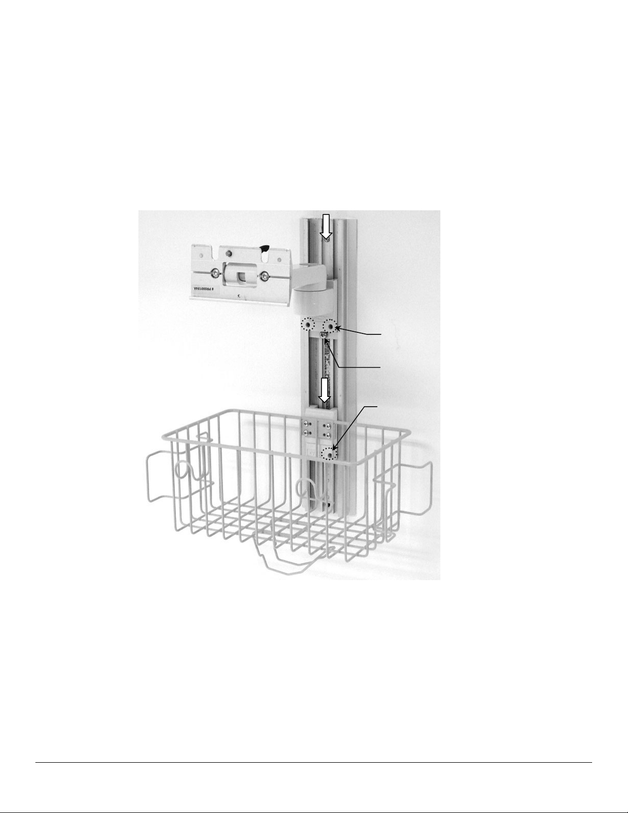
Refer to Photo Below for Steps 2 - 4:
2. Install the Basket by inserting Slide (rear of Basket) into top of Channel and sliding Basket to desired mounting
position. Using the 1/8'' hex wrench provided, tighten the set screw in the bottom right corner of the Slide.
3. Insert Adjustable Stop in top of Channel and let it slide to rest against top of Basket Slide.
4. Install Arm by guiding Slide (rear of Arm) into top of Channel. Slide Arm to desired position in channel and tighten two
(2) set screws (bottom of Slide) using 1/8'' hex wrench provided. Slide Adjustable Stop to bottom of Arm Slide and
tighten center screw in Adjustable Stop.
3 – Slide Arm to Mounting Position, and
Tighten Set Screws with 1/8'' Hex
Wrench.
4 – Slide Adjustable Stop to Bottom of Channel
Slide and Tighten Center Screw in Stop.
2 – Slide Basket to Mounting Position, and
Tighten Set Screw with 1/8'' Hex Wrench.
DU-PR-0013-06 Rev A 2/28/07 GCX Corp Page 2 of 5
Page 3

5. Remove four (4) existing screws from rear of monitor (right). These mounting
y
)
r
holes will be used for attachment of Sub Plate in step 6.
Remove Existing Screws (4
6. Ensure four (4) standoffs on Sub Plate are facing away from the monitor (see below), and fasten Sub Plate to rear of
monitor with four (4) #6-32 x 3'' PHMS as shown below.
Sub Plate
Sub Plate Standoffs (4) Must
Face Awa
from Monitor
Standoffs (4)
#6-32 x 3'' PHMS (4)
7. Fasten Mounting Adapter to standoffs on Sub Plate with four (4) #8-32 x 1/4'' PHMS and #8 flat washers.
Mounting Adapte
#8-32 x 1/4'' PHMS (4)
#8 Washers (4)
Standoffs (4)
DU-PR-0013-06 Rev A 2/28/07 GCX Corp Page 3 of 5
Page 4

8. Lower two (2) Guide Bushings into slots in the Mounting Plate (below left). The Plunger must snap into the clearance
hole to secure the monitor. Ensure bottom edge of Mounting Adapter engages bottom lip of Mounting Plate. Tighten
two (2) Nylon screws to further secure monitor on Mounting Plate (below right).
Lower Guide Bushings into Slots
Tighten Nylon Screws (2)
9. Insert power supply in the Power Supply Hook on the bottom of the Basket. Note: Power supply shown below is
mounted in a Roll Stand-mounted Basket. Wall-mounted Basket is identical.
Power Supply Hook
10. Install the Wall Channel Cover in accordance with the Channel Cover Installation Guide (DU-UT-0001-20).
DU-PR-0013-06 Rev A 2/28/07 GCX Corp Page 4 of 5
Page 5

Adjusting Tilt and Tilt Tension
Tilt Adjustment: Turn Tilt Adjustment Lever counter clockwise to loosen. Lever provides ratchet-style adjustment (see
Installation Note below). Lift and rotate lever to desired position and release, then loosen. Grasp the top and/or bottom
of the device and tilt to the desired angle. Turn Tilt Adjustment Lever clockwise (using ratchet feature as desired) to
tighten and lock position.
Tilt Tension: Adjust the overall tilting tension by evenly tightening or loosening the two (2) Tilt Tension Adjustment
Screws with the 5/32'' hex wrench provided. Once the overall tilt tension is set, use the Tilt Adjustment Lever to fine tune
and lock the tilt position.
Tilt Adjustment Lever
Installation Note: The Tilt Adjustment Lever is
a multi-position clamping lever that operates by
lifting, rotating, and releasing the handle.
Tilt Tension Adjustment Screws (2)
Periodic Maintenance and Cleaning
All fasteners associated with the mounting system should be inspected periodically and tightened as necessary.
The mounting system may be cleaned with any non-abrasive solution as approved by the facility in which the product will
be used.
DU-PR-0013-06 Rev A 2/28/07 GCX Corp Page 5 of 5
 Loading...