

Page 1

2
OEM Implementation Manual
Page 2

Duet CO2Module OEM Implementation Manual
Copyright © 2001 by Welch Allyn OEM Technologies. Welch Allynâ and Protocolâ are
registered trademarks, and Pryonä is a trademark of Welch Allyn, Inc. Welch Allyn, Inc. is
protected under various patents and patents pending. Welch Allyn OEM Technologies is a
division of Welch Allyn, Inc.
Disclaimers: Welch Allyn OEM Technologies cautions the reader of this manual:
• This manual may be wholly or partially subject to change without notice.
• All rights are reserved. No one is permitted to reproduce or duplicate, in any form, the whole
or part of this manual without permission from W elch Allyn OEM Technologies.
For information concerning this document, contact:
Welch Allyn OEM Technologies
8500 SW Creekside Place
Beaverton, OR 97008-7107 U.S.A.
(503) 526-4900
Fax: (503) 526-4901
PN 120.00052 Rev. 1, 10/01
Page 2 Confidential Welch Allyn OEM Technologies
Page 3

Duet CO2Module OEM Implementation Manual
Table of Contents
Functional Description ..................................................................................................................................7
Introduction...............................................................................................................................................7
Intended Use .............................................................................................................................................. 7
Terminology...............................................................................................................................................8
Mainstream vs. Sidestream ...................................................................................................................... 8
Measuring Principle.................................................................................................................................. 8
Measurement Calculation......................................................................................................................10
Breath Algorithm .................................................................................................................................. 10
Measurement Compensation.................................................................................................................10
Water Vapor.......................................................................................................................................... 10
Pressure Broadening .............................................................................................................................10
Gas Mixing............................................................................................................................................11
O
O/desflurane.................................................................................................................................11
2/N2
BTPS..................................................................................................................................................... 11
Hardware Components ................................................................................................................................13
Introduction.............................................................................................................................................13
CO
Main Processor Board.................................................................................................................... 13
2
68HC11 Microprocessor ....................................................................................................................... 14
Reset Circuit..........................................................................................................................................14
Primary Power Supplies........................................................................................................................14
A/D Converter....................................................................................................................................... 14
D/A Converter....................................................................................................................................... 14
Source Hybrid ....................................................................................................................................... 14
Pressure transducers..............................................................................................................................15
Mainstream Components .......................................................................................................................15
Mainstream Daughter Board................................................................................................................. 15
Flex Circuit with Nicolay Receptacle ...................................................................................................15
Mainstream Sensor................................................................................................................................ 16
Airway Adapter..................................................................................................................................... 16
Sidestream Components ......................................................................................................................... 17
Sidestream Daughter Board .................................................................................................................. 17
Pump ..................................................................................................................................................... 17
Water trap Assembly............................................................................................................................. 17
Inlet and Exhaust Tubing ......................................................................................................................18
CO
Sample Line and Cannula..............................................................................................................18
2
Welch Allyn OEM Technologies Confidential Page 3
Page 4

Duet CO2Module OEM Implementation Manual
Duet Configuration Drawings................................................................................................................ 19
Duet CO
Module Interface ......................................................................................................................... 21
2
Power Requirements............................................................................................................................... 21
CO
Main Processor Board.................................................................................................................... 21
2
Duet Module Interface Connector......................................................................................................... 22
Water Trap Receiver Assembly............................................................................................................. 22
Water Trap Switch Connection .............................................................................................................22
Pump ........................................................................................................................................................22
Mainstream Interface ............................................................................................................................. 23
Nicolay Receptacle ...............................................................................................................................23
Mainstream Sensor................................................................................................................................ 24
Sidestream Interface ...............................................................................................................................25
Pump ..................................................................................................................................................... 25
Water trap Receiver ..............................................................................................................................25
Water Trap Receiver Switch .................................................................................................................25
Exhaust Tubing .....................................................................................................................................25
Host/Module Communications .................................................................................................................... 27
Introduction.............................................................................................................................................27
Communication Interface....................................................................................................................... 27
System EEPROM.................................................................................................................................. 27
Packet Communication ......................................................................................................................... 28
Host Commands....................................................................................................................................28
Mode Commands .................................................................................................................................. 29
Simple Commands ................................................................................................................................29
Configuration Commands ..................................................................................................................... 31
Module Responses ................................................................................................................................ 34
Status Responses................................................................................................................................... 34
Status Response Mode Byte.................................................................................................................. 34
Status Response Message Byte ............................................................................................................. 35
Mode Command Responses.................................................................................................................. 36
Simple Command Response .................................................................................................................36
Configuration Command Responses..................................................................................................... 38
Additional Configuration Responses ....................................................................................................39
Software Protocol....................................................................................................................................40
Packets ..................................................................................................................................................40
Sensors .................................................................................................................................................. 40
Faults..................................................................................................................................................... 40
Module Resets....................................................................................................................................... 41
Module Time-outs................................................................................................................................. 41
SYSTEM BEHAVIORS - Dynamic Communications ......................................................................... 41
Status Message Code Table.................................................................................................................... 43
Host Command/Module Response Overview Table............................................................................. 44
Mainstream/Sidestream Hardware Status Table ................................................................................... 45
Mainstream Hardware Status Table ......................................................................................................45
Sidestream Hardware Status .................................................................................................................45
Page 4 Confidential Welch Allyn OEM Technologies
Page 5

Duet CO2Module OEM Implementation Manual
Pneumatic Operation ................................................................................................................................... 47
Introduction.............................................................................................................................................47
Normal Flow ............................................................................................................................................ 47
Pneumatic Events.................................................................................................................................... 47
Total Inlet Occlusion............................................................................................................................. 48
Partial Inlet Occlusion........................................................................................................................... 48
Total Exhaust Occlusion .......................................................................................................................48
Partial Exhaust Occlusion .....................................................................................................................48
Barometric Out Of Range ..................................................................................................................... 49
Unexpected Reverse Flow.....................................................................................................................49
Unexpected Forward Flow.................................................................................................................... 49
Internal Disconnects ...............................................................................................................................49
Water trap Receptacle ...........................................................................................................................49
Sample Chamber................................................................................................................................... 49
Flow Control Circuitry..........................................................................................................................49
Pump Inlet.............................................................................................................................................49
Pump Exhaust .......................................................................................................................................50
Pump Failure........................................................................................................................................... 50
Low Flow .............................................................................................................................................. 50
High Flow .............................................................................................................................................50
No Flow ................................................................................................................................................50
Regulatory ....................................................................................................................................................51
Overview ..................................................................................................................................................51
Welch Allyn OEM Technologies and Compliance with IEC 601-1 ..................................................... 51
OEM Responsibilities ........................................................................................................................... 51
Requirements........................................................................................................................................... 52
Electromagnetic Interference ................................................................................................................ 52
Electromagnetic Susceptibility..............................................................................................................52
Compliance Testing Summary.............................................................................................................. 52
ISO 9918 and EN 864 ........................................................................................................................... 52
Performance Validation............................................................................................................................... 53
Introduction.............................................................................................................................................53
Verification Procedures.......................................................................................................................... 53
Mainstream CO
Sidestream CO
Sensor Verification.................................................................................................... 53
2
Verification.................................................................................................................55
2
Pneumatic System Verification (Sidestream)........................................................................................56
Specifications ...............................................................................................................................................57
Duet CO
Module Specifications............................................................................................................57
2
Welch Allyn Mainstream Sensor II Specifications............................................................................... 61
Adult/Pediatric Single-Use Airway Adapter Specifications ................................................................62
Low Dead Space Single-Use Airway Adapter Specifications ..............................................................63
Adult/Pediatric Multi-Use Airway Adapter Specifications ................................................................. 64
Welch Allyn OEM Technologies Confidential Page 5
Page 6

Duet CO2Module OEM Implementation Manual
Software Procedures ....................................................................................................................................65
CRC Code Calculation ...........................................................................................................................65
CRC Example: ......................................................................................................................................66
O
O/Desflurane Compensation......................................................................................................... 67
2/N2
Percent CO
Calculation........................................................................................................................ 68
2
Software Upgrade ...................................................................................................................................68
Download to FLASH Memory..............................................................................................................68
Command Line Parameters................................................................................................................... 68
Operation...............................................................................................................................................70
Motorola S Record Format....................................................................................................................71
EEPROM Maps............................................................................................................................................73
System EEPROM Map Table ...............................................................................................................73
Mainstream Sensor EEPROM Map Table ............................................................................................ 74
Error Messages & Recovery ........................................................................................................................75
Advisories ............................................................................................................................................. 75
Pneumatic System................................................................................................................................. 77
Soft Faults .............................................................................................................................................78
Sensor Faults......................................................................................................................................... 79
System Faults ........................................................................................................................................ 82
Part Numbers ...............................................................................................................................................85
Welch Allyn OEM Technologies Part Numbers...................................................................................85
Inclusions .............................................................................................................................................. 86
Glossary ........................................................................................................................................................ 87
CO2 Developer’s Kit..................................................................................................................................... 93
Introduction.............................................................................................................................................93
Disclaimer ............................................................................................................................................. 93
Software Installation............................................................................................................................... 93
Initial Setup .............................................................................................................................................94
Overview ..................................................................................................................................................95
Main Screen Illustration........................................................................................................................95
Menu Options Description ....................................................................................................................96
CO2 Evaluation Platform...................................................................................................................... 99
Page 6 Confidential Welch Allyn OEM Technologies
Page 7

Duet CO2Module OEM Implementation Manual
Functional Description
Introduction
The Duet CO2Module is designed to acquire data from either an external Welch Allyn OEM
Technologies mainstream CO
includes a sidestream CO
sensor or an internal sidestream system. The sidestream system
2
bench, electronics and pneumatic components.
2
The Duet CO
CO
waveform to the host system via a serial communications interface.
2
Module calculates CO2measurements and respiratory rate and outputs this data with
2
Intended Use
The Duet module is intended for use as a subsystem within a medical instrument or device. The
Module measures levels of carbon dioxide continuously or intermittently in the mainstream or
sidestream mode. The mainstream sensor, in conjunction with the module integrated into the host
system, allows for monitoring of intubated patients. The sidestream mode allows for monitoring of both
intubated and non-intubated patients. The module and its accessories should always be used as
described in the host system operator’s manual and only for the purpose(s) intended. The areas of
intended use include:
• Hospital Intensive Care Units (ICU)
• Hospital Emergency Department/EMS (ED/EMS)
• Surgical Operating Rooms (Anesthesia)
• Hospital Post Anesthesia Care Units (PACU)
• Outpatient Surgical Units
• Skilled Nursing Facilities / Sub-acute Care
• Transport (Air, Ground and Sea)
• Home Care / Traditional Health Care
The most common user will be the skilled professional nurse in the PACU, ICU, or step-down unit. In
addition, knowledgeable users in EMT and other higher care areas will make use of end tidal CO
.
2
Welch Allyn OEM Technologies Confidential Page 7
Page 8
Duet CO2Module OEM Implementation Manual
Terminology
Capnography is the noninvasive measurement and graphic display of airway CO2concentration as a
function of time. The resulting waveform is called a capnogram. The evaluation of the capnogram is
useful in the assessment of the adequacy of carbon dioxide exchange in the lungs, integrity of the
patient’s airway, cardiopulmonary function and ventilator function.
Monitoring of CO
concentration at the end of expiration (point D) is referred to as End-Tidal CO
2
2
(ETCO2) monitoring.
76
CO
2
40
CD
(mmHg)
0
AB
E
Time
Mainstream vs. Sidestream
The patient’s expired gas may be sampled either directly off the airway external to the Duet Module or
aspirated from the patient through a cannula into the Module. The method used is dependent on the
patient’s airway status.
Mainstream capnography is used on intubated or tracheostomy patients. Intubation is the process of
inserting a tube into the patient’s trachea to deliver gases to the lungs. The sample chamber and CO
sensor are in line between the patient’s airway and the ventilator circuit. The signal is acquired external
to the Duet CO
Module while the module executes measurement calculation.
2
2
Sidestream capnography is used on patients who are intubated or non-intubated. The patient’sexpired
gas is aspirated from the airway and transported to the Duet Module through a sample line. The
sidestream sample chamber and sensor are embedded within the Duet CO
Module. The Duet CO
2
2
Module performs signal acquisition and measurement calculation.
The Duet CO
and sidestream input, hence the name Du
Module is designed to accommodate both Welch Allyn OEM Technologies mainstream
2
al End-Tidal (Duet) CO2Module.
Measuring Principle
CO2measurement is based on the infrared (IR) absorption characteristic of CO2molecules. The CO
sensor uses non-dispersive IR spectroscopy to measure the number of CO2molecules present in the
sample gas. CO
mass. CO
2
gas has a unique absorption band that is related to CO2molecule’s composition and
2
gas concentration is measured by detecting absorption in this band. The same
measurement technique is used for both mainstream and sidestream applications. Due to the nature of
the measurement technique employed, user calibration is not necessary with this system.
Page 8 Confidential Welch Allyn OEM Technologies
2
Page 9

Duet CO2Module OEM Implementation Manual
The basic components of the CO
sensor include
2
§ IR source § chopper wheel
§ IR detector § thermistor
§ optical filter § non-volatile memory
§ heater (mainstream only)
The IR source emits energy that is directed toward an IR detector. The detector generates a voltage
based on the amount of energy it receives. In the IR path between the IR source and the detector are
three components: an optical filter, which allows only a specific IR wavelength to pass, a gas sample
in the airway adapter and a chopper wheel. The chopper wheel has three distinct areas: a reference
gas cell, an open area and a dark, or closed area.
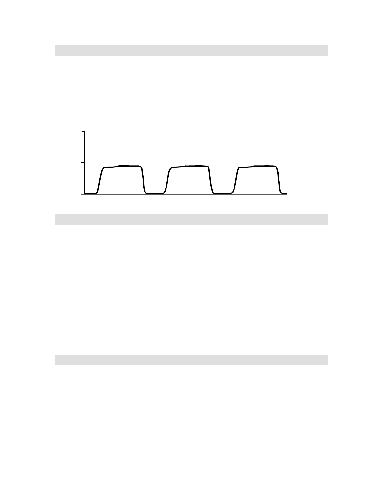
The chopper wheel rotates at 33 revolutions per second. As the single IR beam encounters the three
areas of the rotating chopper wheel, a signal is generated to create a ratio.
REFERENCE +
SAMPLE
DARK
SAMPLE
PHOTODETECTOR VOLTAGE
TIME
This ratio of “reference + patient sample/patient sample” is used to determine the CO2concentration in
the patient’s respiratory gas. This reduces error due to the variability in system components and
minimizes the effects of patient obstructions and secretions on the measurement. The dark area of the
chopper wheel provides a zero reference for re-calibrating the detector with each rotation. This results
in a self-calibrating system.
Since mainstream applications typically involve humidified circuits which can result in fog or
condensation on the airway adapter windows, it is necessary to use a heater to elevate the window
temperature above that of the exhaled respiratory gas. By doing so, the heater keeps the airway
adapter windows clear of condensation while also maintaining a stable detector temperature.
NOTE The optimal operating temperature for the mainstream sensor is 42
The thermistor provides temperature feedback to the heater control circuitry.
The non-volatile memory is an EEPROM containing calibration and manufacturing data specific to the
CO
sensor.
2
Welch Allyn OEM Technologies Confidential Page 9
o
C.
Page 10

Duet CO2Module OEM Implementation Manual
Measurement Calculation
Measurements provided to the host system include ETCO2, Inspiratory CO2(InsCO2), or baseline CO2,
and respiratory rate (RR). These three measurements are collectively referred to as breath data. A
proprietary breath algorithm is used to calculate the breath data.
Breath Algorithm
Duet’s breath algorithm incorporates an initial learning period which, based on certain assumptions of
waveform morphology, establishes CO2reference points for threshold determinations. A sliding
CO
2
window is used to detect a stable maximum, or ETCO
value, and a baseline, or InsCO2value.
2
Thresholds are updated in real time with each breath. A signal averaging technique is used to calculate
the RR based on this set of measurements. By incorporating these adaptive and signal averaging
techniques, the breath algorithm effectively reports accurate CO
measurements while maintaining a
2
high level of noise immunity.
Measurement Compensation
IR absorption in the CO2wavelength band can be affected by a number of factors that alter the CO
measurement. The Duet Module automatically compensates for some of these factors while others
may be disabled by the host system.
These factors include
2
• water vapor
• pressure broadening
• gas mixing
• oxygen, nitrous oxide and desflurane or O
• B
ody Temperature, ambient Pressure and Saturated with water vapor or BTPS
O/desflurane
2/N2
Water Vapor
Water vapor compensation accounts for the effect that water vapor has IR absorption characteristics of
CO
molecules. During normal mainstream or sidestream operation, CO2measurements are adjusted
2
mathematically to compensate for this effect.
The host may choose to disable this compensation when performing a dry gas measurement in which
the gas does not contain water vapor. Dry gas procedures may include steady state measurements
and verification procedures. Steady state measurements are performed only when background CO
CO
present in the immediate environment, is measured. An example of a steady state measurement
2
is measuring the CO
content inside an incubator. Verification procedures use calibrated gas that is
2
,or
2
free of water vapor, or dry, as well.
The water vapor compensation is ON by default and may be enabled or disabled via a host system
command.
Pressure Broadening
Pressure broadening compensation accounts for the effects the barometric pressure has on CO
molecule distribution and is used in both mainstream and sidestream mode operation.
2
The pressure broadening compensation is ON by default and cannot be disabled by the host system.
Page 10 Confidential Welch Allyn OEM Technologies
Page 11

Duet CO2Module OEM Implementation Manual
Gas Mixing
A small amount of gas “mixing” occurs as the CO2sample travels through the tubing to the sample
chamber. Gas mixing compensation accounts for the effect of low level gas mixing on the baseline
during inspiration in sidestream mode operation.
The gas mixing, or baseline, compensation is ON by default and cannot be disabled by the host
system.
O2/N2O/desflurane
O2/N2O/desflurane compensations account for effect of these gases on the IR absorption
characteristics of CO
recommendation for enabling these compensations.
molecules. Refer to page 67 for a description of this effect and a
2
The O
O/desflurane compensation is OFF by default and may be enabled or disabled via a host
2/N2
system command.
BTPS
Often the clinician’s intent is to determine the CO2levels within the patient’s lungs where gas exchange
is taking place. BTPS compensation corrects for the environmental differences between the
measurement site (i.e. the bench) and “deep lung” CO
The BTPS compensation is ON by default and may be enabled or disabled via a host system
command.
.
2
Welch Allyn OEM Technologies Confidential Page 11
Page 12

Duet CO2Module OEM Implementation Manual
Page 12 Confidential Welch Allyn OEM Technologies
Page 13

Duet CO2Module OEM Implementation Manual
Hardware Components
Introduction
The OEM defines the resident Duet CO2Module hardware necessary for mainstream and/or
sidestream operation. Configurations may include mainstream and sidestream sampling (MS/SS Duet
CO
Module), mainstream sampling only (MS Duet CO2Module) or sidestream sampling only (SS Duet
2
Module). Refer to 19 for drawings of these configurations.
CO
2
An additional consideration is the inclusion of an isolated power supply. Mainstream operation requires
an isolated power supply to meet patient safety requirements.
NOTE The OEM must supply Patient isolation when using mainstream Duet and the mainstream
sensor.
The motherboard for all Duet CO
Module configurations is referred to as the CO2main processor
2
board. Mainstream and sidestream sampling requires the addition of the mainstream and/or sidestream
daughter boards with associated hardware to function.
CO2 Main Processor Board
The CO2main processor board provides the interface to the mainstream and sidestream daughter
boards and the host system; manages power requirements; calculates measurements; and regulates
heater output and pump flow.
The functional components of the CO
§ 68HC11 microprocessor with external memory
§ reset circuit
§ primary power supplies
§ analog to digital (A/D) converter
§ digital to analog (D/A) converter
§ source hybrid
main processor board include
2
§ barometric pressure transducers
Welch Allyn OEM Technologies Confidential Page 13
Page 14

Duet CO2Module OEM Implementation Manual
68HC11 Microprocessor
The microprocessor controls feedback to the temperature and pressure transducers, heater output in
mainstream applications and pump flow in sidestream applications. The microprocessor also provides
the communication interface to the host system and the interfaces to the external A/D and D/A
converters and sensor EEPROM memory. An internal multiplexed A/D converter is used for digital
conversion and for monitoring some of the power supplies for fault determinations.
All address decoding is done by the microprocessor. The software code is stored in FLASH memory
and is supplemented by an external static RAM chip. The boot mode of the microprocessor is used to
install new software into the FLASH device.
Reset Circuit
The first section of a 556 timer is connected to a serial receive data line such that the microprocessor is
forced into reset if the data line is held in a break condition for greater than 10 msec. A second timer
section is used to ascertain if the break condition is maintained for more than 500 msec.
Holding the receive data line in a break condition for a period of time greater than 10 msec and less
than 500 msec is referred to as a reset.
A hard reset occurs when the break condition is held longer than 500msec. This condition forces the
microprocessor to enter the boot mode after the break is released.
A reset controller performs power ON, reset and low voltage lockouts. Under voltage lockout is set to
approximately 4.5 V. On power up, the microprocessor is held in reset for about 100 msec after the
supply rises above 4.5 V.
Primary Power Supplies
All primary power supplies run off a single voltage power source and are converted on the main board
to various levels. With the Duet CO
power supplied by the host system.
V
IN
Module, the power source is derived from the +8.00 - +12.00 VDC
2
The +8.00 VDC minimum requirement may be reduced if longer mainstream sensor warm up times are
acceptable or if only sidestream operation is intended.
A/D Converter
The 8 channel 12 bit serial A/D converter converts the following analog signals into a binary data
stream for the microprocessor: analog waveform from the optical bench, temperature of the optical
bench, barometric pressure, pneumatic flow rate (sidestream).
D/A Converter
The 12 bit serial interface D/A converter provides bench motor speed control, source current selection
and detector bias circuit control.
Source Hybrid
The optical benches require that the IR sources be current regulated. The current sensing circuitry is
located on a ceramic hybrid module, or source hybrid. A regulator is used that adjusts its output voltage
to maintain a constant current. The output of the regulator is then fed to a switch that can route the
output to either the mainstream or sidestream board.
Page 14 Confidential Welch Allyn OEM Technologies
Page 15

Duet CO2Module OEM Implementation Manual
Pressure transducers
The barometric pressure circuitry monitors pressure via transducers in order to compensate for the
effect of pressure variation on CO
measurements. The transducers include:
2
§ an absolute pressure transducer which monitors the ambient pressure for pressure broadening
effects on the CO
signal.
2
§ a second absolute pressure transducer that monitors internal bench pressures.
§ a differential pressure transducer that is used for pump flow regulation.
Mainstream Components
The functional components necessary for mainstream operation include
§ mainstream daughter board
§ flex circuit with Nicolay receptacle
§ mainstream sensor
§ airway adapter
Mainstream Daughter Board
The mainstream daughter board, or mainstream stick, provides controls to start and maintain the
chopper motor speed; controls to regulate heater output and monitor sensor temperature; and logic for
mainstream fault sensing.
The functional components of the mainstream daughter board include the motor control hybrid, the
heater control circuitry and the flex circuit connector.
The motor control hybrid operates via drive coils in the chopper motor to provide feedback to the
microprocessor to drive the motor. The microprocessor uses this signal to synchronize the waveform
signal with the chopper motor and to start and maintain the motor speed.
The heater control circuitry controls the heater output and monitors internal bench temperature. A
signal from the microprocessor is applied to the heater element in the sensor head. A thermistor
located in the sensor housing provides temperature feedback to the heater control. This feedback is
used to control the sensor housing temperature.
The heater power supply uses a pulse width modulated, or PWM, signal to step down the raw input
voltage to a level appropriate for maintaining the mainstream sensor at 42
o
C.
The flex circuit connector on the mainstream daughter board provides electrical connection of the flex
circuit to the mainstream daughter board.
Flex Circuit with Nicolay Receptacle
The flex circuit with Nicolay receptacle interfaces the mainstream sensor to the mainstream daughter
board.
The functional components of the flex circuit with Nicolay receptacle include the Welch Allyn OEM
Technologies flex circuit, or flex circuit, and the Nicolay receptacle.
Welch Allyn OEM Technologies Confidential Page 15
Page 16

Duet CO2Module OEM Implementation Manual
NOTE Flex circuit and Nicolay receptacle are not included with the MS/SS and MS Duet CO
2
Modules and may be ordered separately from Welch Allyn OEM Technologies or supplied
directly by the OEM.
NOTE Flex circuit layout and dielectric strength may be customized as per OEM requirements. The
OEM must supply routing and layout drawings to Welch Allyn OEM Technologies for a
custom flex design. Consult with Welch Allyn OEM Technologies for additional information
on ordering a custom flex circuit.
The Welch Allyn OEM Technologies flex circuit is double-insulated to provide single fault protection
and provides up to 10kV dielectric strength.
The Nicolay receptacle is fastened to the housing of the host system and provides the interface for the
mainstream sensor.
Mainstream Sensor
The mainstream sensor houses the hardware necessary to determine the CO2molecule count in the
sample chamber. The IR beam passes from the IR source on one side of the sensor housing through
the windows of the airway adapter to the other side of the housing. This output is communicated to the
Duet CO
The functional components of the mainstream sensor include the mainstream sensor connector, cable
and mainstream sensor head.
NOTE Mainstream sensor is not included with the MS/SS and MS Duet CO
Module for measurement calculation.
2
ordered separately from Welch Allyn OEM Technologies.
Modules and must be
2
The mainstream sensor connector interfaces the mainstream sensor to the Nicolay receptacle.
Within the mainstream sensor connector is an EEPROM that retains calibration information for the
sensor and OEM specific information that allows the sensor to be used only with the electronics
identified for a specific OEM.
NOTE Mainstream sensor EEPROM is pre-configured by Welch Allyn OEM Technologies after
obtaining OEM specific information.
The cable connects the mainstream sensor connector to the mainstream sensor head.
The mainstream sensor head houses the IR optical components, chopper drive motor and
mainstream sensor circuit board. The inverted U-shaped housing of the mainstream sensor head
snaps onto the airway adapter.
Airway Adapter
The airway adapter is used as the sample chamber for the sensor and is connected between the
endotrachial tube and the ventilator’s wye piece. A variety of airway adapters are available. Selection is
typically based on adult/pediatric/neonate status, multiple use versus disposable and low dead space
performance.
NOTE Airway adapter is not included with the MS/SS and MS Duet CO
ordered separately from Welch Allyn OEM Technologies.
Modules and may be
2
Page 16 Confidential Welch Allyn OEM Technologies
Page 17

Duet CO2Module OEM Implementation Manual
Sidestream Components
The functional components necessary for sidestream operation include
§ sidestream daughter board
§ pump
§ Water trap assembly and receiver
§ inlet and exhaust tubing
§ CO
sample line/cannula
2
Sidestream Daughter Board
The sidestream daughter board provides the interface to the sidestream CO2sensor; pump and Water
trap receiver switch; controls to start and maintain the chopper motor speed; and provides feedback to
regulate the pump flow.
The functional components of the sidestream daughter board include the sidestream bench, the motor
control hybrid (refer to Mainstream Components section), the flow control circuitry and the pump and
Water trap assembly connectors.
Apart from the absence of a heater, the sidestream bench operates in the same manner as the
mainstream sensor. Additionally, the microprocessor monitors the internal sensor temperature through
thermistor feedback to compensate for temperature variation.
The flow control circuitry regulates flow using a fixed orifice flow sensor that provides feedback to a
circuit controlling power to the pump. A differential pressure transducer measures the pressure drop
across a restrictor. It is used as feedback to adjust the pump speed. The pump power supply steps
down the raw voltage applied to the board to a level appropriate for maintaining the desired pump flow
rate.
The pump connector provides electrical connection of the pump to the sidestream daughter board.
The Water trap assembly connector provides electrical connection of the Water trap switch to the
sidestream daughter board.
Pump
The electrically driven miniature oil-free diaphragm pump draws the sample through the sample line to
the sample chamber by creating a vacuum. Fault states such as exhaust and Water trap occlusions are
recognized by the flow control circuitry.
Water trap Assembly
The Water trap assembly provides the principal filter medium for the airway gas sample before the gas
is delivered to the sample chamber.
The functional components of the Water trap assembly include the Water trap, the W ater trap receiver
and the Water trap receiver switch.
NOTE Water trap, Water trap receiver and Water trap receiver switch are not included with the
MS/SS and SS Duet CO
Technologies or supplied by the OEM.
Welch Allyn OEM Technologies Confidential Page 17
Modules and may be ordered separately from Welch Allyn OEM
2
Page 18

Duet CO2Module OEM Implementation Manual
The Water trap is a user-supplied cartridge that removes excess moisture in the sample line before the
sample is delivered to the sample chamber. The Water trap is designed to fully occlude once the filter is
saturated.
The Water trap receiver is the receptacle for the Water trap and can be molded by the OEM into the
main housing of the host monitor. The external end of the Water trap is connected to the sample line.
The Water trap receiver switch assembly ensures that the W ater trap is properly inserted into the
Water trap receiver before the pump begins operation. This eliminates the possibility of the user
bypassing the Water trap.
Inlet and Exhaust Tubing
The internal inlet tubing provides the means to transport the airway gas sample from the Water trap
receiver to the sidestream bench. The inlet tubing includes the tubing, connectors and a secondary
shutoff pellet. Attachment of the inlet tubing to the Water trap receiver is via a Luerâ connector. A
secondary shutoff pellet is attached in line with the inlet tubing to provide additional insurance for
saturation detection.
The exhaust tubing provide the means to expel the exhaust gas. A filter, or 5um screen, is in line with
the exhaust tubing to muffle, or reduce the pump noise.
CO2 Sample Line and Cannula
ACO2sample line, or sample line, is used to transport the airway gas sample from patient to the Water
trap assembly. Connection of the sample line on the patient side is via a female oriented Luerâ
connector attached to the sample line.
Note: Sample lines are not included with the Duet CO
Module and may be ordered separately from
2
Welch Allyn OEM Technologies or other suppliers.
For non-intubated patients, the sample line connects to a cannula that is positioned on the patient. A
variety of cannulas are available to accommodate patient requirements. Nasal, oral/nasal and divided
cannulas that deliver oxygen and sample CO
Note Cannulas are not included with the Duet CO
simultaneously may be used.
2
Module and may be ordered separately from
2
Welch Allyn OEM Technologies or other suppliers.
For an intubated patient, the sidestream sample line connects to the patient’s breathing circuit.
Page 18 Confidential Welch Allyn OEM Technologies
Page 19
Duet CO2Module OEM Implementation Manual
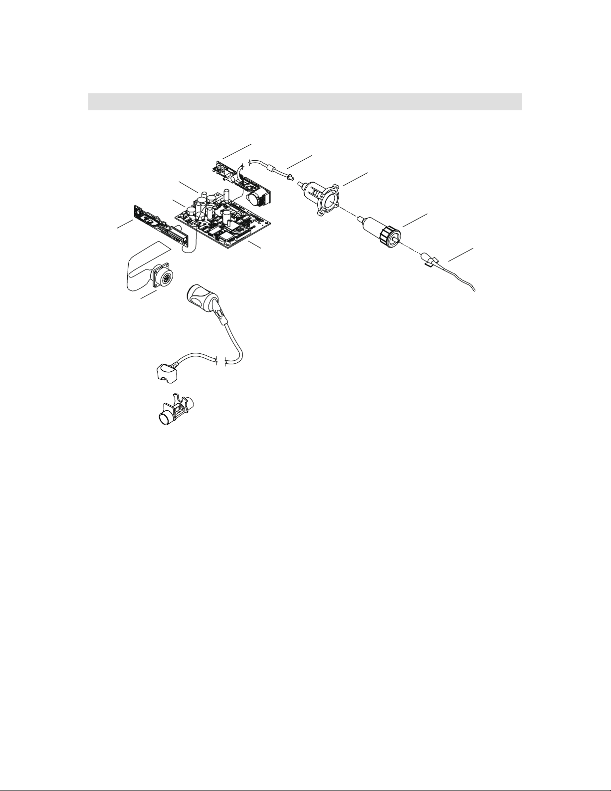
Duet Configuration Drawings
Sidestream
Stick
Host System
Serial Port
Interface
Power
Secondary
Shut Off
Watertrap
Receptacle
Watertrap
Mainstream
Stick
Nicolay
Receptacle
Mainstream
Sensor
Main PWB
Airway Adapter
(Adult, Neonatal or Reusable)
Nasal
Cannula
Sidestream and Mainstream
Measurement System
Welch Allyn OEM Technologies Confidential Page 19
Page 20
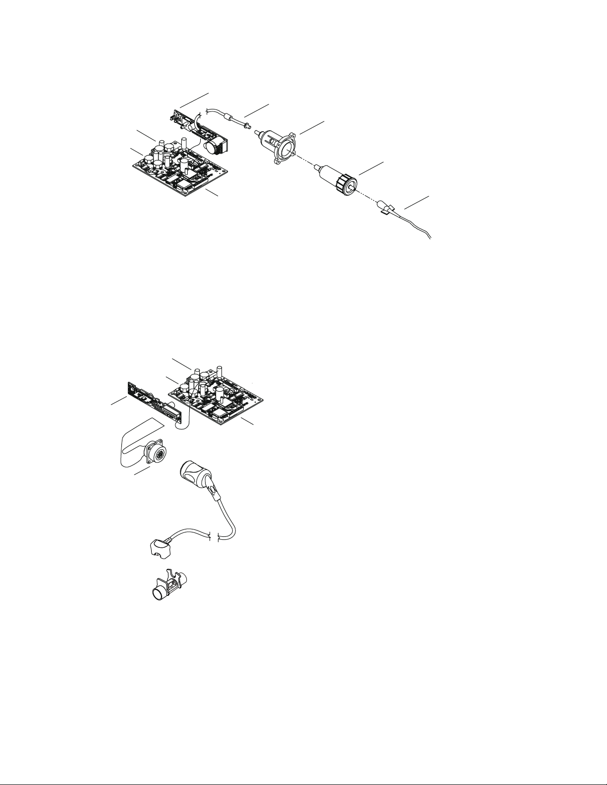
Host System
Serial Port
Interface
Power
Sidestream
Stick
Duet CO2Module OEM Implementation Manual
Secondary
Shut Off
Watertrap
Receptacle
Watertrap
Host System
Mainstream
Stick
Main PWB
Sidestream
Measurement System
Serial Port
Interface
Powe r
Nasal
Cannula
Main PWB
Nicolay
Receptacle
Mainstream
Measurement System
Mainstream
Sensor
Airway Adapter
(Adult, Neonatal or Reusable)
Page 20 Confidential Welch Allyn OEM Technologies
Page 21

Duet CO2Module OEM Implementation Manual
(
)
Duet CO2 Module Interface
Power Requirements
Description Typical
Input voltagerange +8.00 to +12.00 VDC, 150 mV peak to peak ripple
Non-measurement power 570 mW at +8.00 VDC
Mainstream warm up power 5 W at +8.00 VDC
Mainstream operating power 2.8 W at 25° C, average
Sidestream operating power 1.3 W at +8.00 VDC
Sidestream occluded power 1.8 W at +8.00 VDC
Sidestream pump stalled power 3.0 W at +8.0 VDC
a. Optimal input voltage is +8.00 VDC. Typical power consumption increases slightly with higher input
voltages.
a
The host must supply fused input voltage to the Duet CO
the power input side of the Duet CO
voltage) and 1.50 A (8.00 V input voltage).
Module are 1.00 A (12.00 V input voltage), 1.25 A (10.00 V input
2
CO2 Main Processor Board
Description Specification
Dimensions
(MS & SS included)
Clearance 1.00 in (25.40 mm) above board
Orientation No limitations
Weight < 1 lb (454 gm)
3.15 in L × 3.90 in W × 1.22 in H
80 mm L×100 mm W×31 mm H
0.20 in (5.00 mm) below board
Module. The actual slo blo fuse values for
2
Welch Allyn OEM Technologies Confidential Page 21
Page 22

Duet CO2Module OEM Implementation Manual
Duet Module Interface Connector
The module interface connector is a 4 pin connector (Molex p/n 22-11-2042). The host may usea4pin
polarized housing (Molex p/n 22-01-3047 with Molex 2759 series terminals) or equivalent.
Pin Signal Signal Description
1V
2 GND ground
3 TxD data from CO2main processor board to host system
4 RxD data from host system to CO2main processor board
a. The “square” plated through-hole designates pin 1 on the CO2main processor board.
input power
Water Trap Receiver Assembly
The internal space available in the host monitor should be considered when incorporating the Water
trap receiver into the host system design. To accommodate various OEM dimensions, two water trap
receivers are offered: long and short. The long Water trap receiver requires more intrusion into the host
monitor but the Water trap does not protrude as far externally from the host chassis than with the short
Water trap receiver. The Water trap receiver assembly includes a mounted micro-switch to detect the
insertion of a Water trap.
Water Trap Switch Connection
The Water trap receiver switch is wired in the “normally open” configuration.
The Water trap switch connection is available via the connector on the sidestream daughter board. The
switch assembly is equipped with a 2-pin connector (Molex P/N 22-01-3027) which electrically
connects directly to the sidestream daughter board at P502.
Pump
The pump is mounted on the Main Processor Board. The pump wiring harness is connected to the
sidestream daughter board via a 2-pin connector (Molex P/N 22-01-3027).
Page 22 Confidential Welch Allyn OEM Technologies
Page 23
Duet CO2Module OEM Implementation Manual
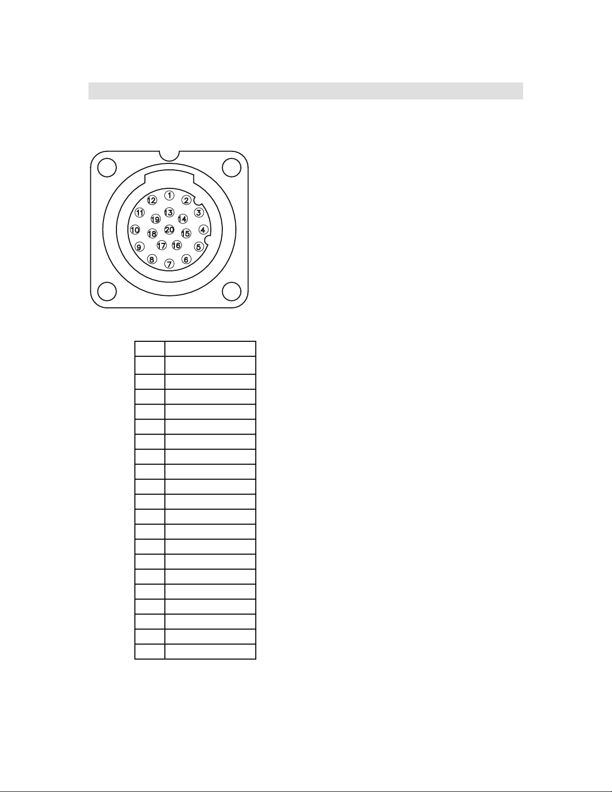
Mainstream Interface
Nicolay Receptacle
Pin Signal
1 sense ground
2 - bias
3 ground return
4 thermistor
5drivecoil
6 + bias
7 ground return
8 IR detector output
9+5V
10 IR source
11 ground return
12 heater
13 signal ground
14 -5 V
15 EEPROM clock
16 sense coil
17 EEPROM data
18 EEPROM CS
19 N/C
20 ground return
Welch Allyn OEM Technologies Confidential Page 23
Page 24

Duet CO2Module OEM Implementation Manual
g
a
Mainstream Sensor
Description Specification
Dimensions
Weight < 1.25 oz (18.5 gm) without cable
Cable Length 10 ft / +1.0 in / -4.0 in
Volume approximately 1.0 in3(16.59 cm3)
The mainstream sensor warm up has three phases: preliminary warm up, sensor start up and final
warm up. The preliminary warm up phase is the primary warming period. Once the sensor reaches the
near final temperature of 42
conditions are met, the mainstream sensor returns to complete the warm up phase.
Phase/Task Elapsed Time (typical) Response Suggested Message
Preliminary/
Warm sensor
0.75 in L × 1.35 in W × 1.00 in H
(19.5 mm L × 34.29 mm W × 25.4 mm H)
(3.5 m / +2.5 cm / -10.2 cm)
o
C, the sensor progresses to the sensor start up phase. Once start-up
45 - 90 seconds <S0310> Sensor Warming
Sensor start up/
5 - 10 seconds <S0311> Sensor Warming
Start sensor motor
Final warm up/
10 seconds <S0311> Sensor Warming
Turn on IR source and
wait for si
nal
The warm up time of the mainstream sensor is dependent on the ambient temperature and the power
available to the heater circuit.
Note: If less power is supplied, the Duet CO
Module may be configured for a longer warm up time.
2
The following table lists typical approximate warm up times based on these variables in minutes.
Temperature 2.5 W
3.5 W 4.5 W 5.5 W
5oC 9:50 5:00 3:00 2:20
25oC 3:00 1:40 1:00 0:40
40oC 0:50 0:20 0:15 0:15
a. Power delivered to the sensor. For example, to supply 2.5 W to the sensor, the CO2main processor
board needs 3.5 W.
After operating temperature is reached, the bench motor is started and the signal acquisition begins to
servo the bench signal into the operating range. This may add 20 to 30 seconds to the warm up time.
Page 24 Confidential Welch Allyn OEM Technologies
Page 25

Duet CO2Module OEM Implementation Manual
Sidestream Interface
Pump
The pump is mounted on the CO2main processor board and is electrically connected directly to the
sidestream daughter board. The pump wiring harness length is typically 4 inches and is connected to
the sidestream daughter board viaa2pinconnector (Molex p/n 22-01-3027).
Note: The pump wiring harness length may be modified to accommodate OEM design
requirements if, for example, the pump requires mounting off of the main processor board.
The pump wiring meets typical insulation standards but does not meet patient isolation
requirements. If the pump must be moved to a different location, such as a non-isolated section,
patient isolation requirements must not be compromised. Refer to Regulatory Section for
additional safety information.
Water trap Receiver
The internal space available in the host monitor must be considered when incorporating the Water trap
receiver into a design. To accommodate this requirement, two Water trap receivers are offered: the
long and short receiver. The short Water trap receiver offers less intrusion into the host monitor but
causes the Water trap to extend further externally.
Water Trap Receiver Switch
The Water trap receiver switch is wired in the “normally open” configuration.
The Water trap receiver switch connects directly to the sidestream daughter board via a wiring harness
and connector. The Water trap receiver switch assembly is equipped witha2pinconnector (Molex p/n
22-01-3027) which electrically connects directly to the sidestream daughter board. A wiring harness is
provided and may be altered to accommodate OEM design requirements.
Note: The Water trap receiver switch wiring meets typical insulation standards but does not meet
patient isolation requirements. W hen applicable, harness routing must not violate patient isolation
requirements. Refer to Regulatory Section for additional safety information.
Exhaust Tubing
In the event of an exhaust tubing malfunction, gas buildup can occur within the host system.
WARNING To protect against this occurring, exhaust tubing must be single fault protected.
Welch Allyn OEM Technologies Confidential Page 25
Page 26

Duet CO2Module OEM Implementation Manual
Page 26 Confidential Welch Allyn OEM Technologies
Page 27

Duet CO2Module OEM Implementation Manual
Host/Module Communications
Introduction
The Duet CO2Module is a command driven slave device capable of communicating with a host system
over an asynchronous serial communication line. After start up, the Duet CO
periodic CO
by the host system to the Duet CO
waveform and breath data packets to the host system. All other communication is initiated
2
Module.
2
Module communicates
2
The Duet CO
Module and the host system are referred to as the “module” and host” in this chapter.
2
Communication Interface
§ 9600 baud rate (user-selectable)
§ full duplex
§ Asynchronous using standard non return to zero (NRZ) format.
{1 start bit 7 or 8 data bits even parity 1 stop bit}
§ Receive data input (RxD) is the buffered input of a 74HC14. A pull-up is provided on the
module so it can be driven by an open collector source.
§ Transmit data output (TxD) is the collector of a 2N4401 transistor driven with a 10 K base
resistor from the output of a 74HC14. A weak pull-up is provided to source a CMOS load.
§ Non-isolated module power and communications are provided at P104.
System EEPROM
System EEPROM contains system configuration and operational constants that are encoded by Welch
Allyn OEM Technologies. While the majority of parameters pertain to Welch Allyn OEM Technologies
manufacturing and operational defaults, specific parameters may be customized to accommodate
OEM requirements.
System parameters that the OEM may specify a default value include
§ baud rate § module start up mode
§ data format § initial pump flow rate
The baud rate may be set to a maximum of 9600. (Defaults to 9600.)
Welch Allyn OEM Technologies Confidential Page 27
Page 28

Duet CO2Module OEM Implementation Manual
The data format options are 7 or 8 bits. (Defaults to 7 bit.)
The module start up mode options are auto run, measurement, warm standby, standby and fault.
(Defaults to sidestream fault mode.)
The initial pump flow rate option allows the host to specify desired default flow rate. (Defaults to
175ml/min.)
Refer to the System EEPROM Map Table in Appendix A Software Procedures for further information.
Packet Communication
Transmission of host commands and module responses is via packets. The following byte structure
represents a packet.
Packet format:
< start of text (STX) 02h
X identifier 1*(ASCII)
n
xx
yy CCITT/CRC code 2*(ASCII)
> end of text (ETX) 03h
data n(hex char)
ASCII characters have values in the range of 00h to 7Fh. The identifier is case sensitive. Characters
between 00h and 20h are reserved as control characters.
Transmission of all packets starts with a “<” STX control character and ends with a CCITT/CRC code
and “>” ETX control character. Between STX and ETX is an identifier and n bytes of ASCII data. The
length of the packet is defined by the identifier character. Packet length cannot exceed 25 bytes with a
maximum of 20 bytes of data allowed. Packets without the STX control character are ignored. The
CRC code is computed on values between STX and CRC code.
02h X xxnyy 03h
Host Commands
The host communicates to the module via commands. These include
§ mode commands, to request a change in the operating mode.
§ simple commands, to request data or a status change. Data is not sent with these commands.
§ configuration commands, to specify custom system settings. Data is sent with these
commands.
Page 28 Confidential Welch Allyn OEM Technologies
Page 29

Duet CO2Module OEM Implementation Manual
Mode Commands
Mode commands allow the host to put the module into one of the four operating modes.
Host Command Description
<M04> for MS
<M24> for SS
Enter auto run mode
To start automatic sampling and data packet transmission at default
intervals of real time CO
waveform and breath data. A mainstream
2
sensor disconnect or a sidestream water trap removal causes the
module to wait for a sensor reconnect or sidestream Water trap
insertion. This is the preferred operating mode since temporary
sensor removal and replacement is typical in normal operation.
<M03> for MS
Enter measurement mode
<M23> for SS
Same as auto run mode except for mainstream sensor disconnects
and sidestream Water trap removals. Instead of waiting for a sensor
reconnect or Water trap insertion, the sensor’s activity is halted and
the module reverts to the standby mode and requires a new <M03>
or <M23> host command to restart measurement.
<M02>
Enter warm standby mode
Provides a low power standby state for the module during sensor
warm up in mainstream operation since warm up time may be as long
as several minutes. Standby mode keeps the sensor warmed and
ready. Standby mode also reduces battery drain.
<M01> for MS
Enter standby mode
<M21> for SS
Used when a low power standby state for the module is desirable.
This prolongs the life expectancy of the IR source, chopper motor and
heater since these components are disabled in this mode.
The module automatically reverts to a fault mode if a module or sensor fault occurs. A message is sent
via the status response by the module to the host.
Simple Commands
Simple commands instruct the module to send module data or sensor EEPROM data and to reset the
module software or a sensor error.
Host Command Description
<C00>
Request module status
To confirm operating mode, fault status and module and sensor
operation.
<C20> Request software version
<C21> Request hardware version
Welch Allyn OEM Technologies Confidential Page 29
Page 30

Duet CO2Module OEM Implementation Manual
Host Command Description
<C22> Request ambient barometric pressure
To calculate %CO
.
2
<C23> Request sensor temperature
<C24> Request chopper motor speed
<C26> Request single CO2measurement
<C24> Request single breath data packet
<C2E> Request current pump flow rate
<C31> Request sensor EEPROM revision #
<C32> Request sensor OEM specific code
<C33> Request sensor serial #
<C3A> Request last calibration date
<C80> Software reset
<C82> Clear sensor error
To retry or verify fault condition.
Page 30 Confidential Welch Allyn OEM Technologies
Page 31

Duet CO2Module OEM Implementation Manual
Configuration Commands
Configuration commands instruct the module to temporarily modify specific default settings for
measurement criteria. A new pump flow rate may also be specified.
A description of these commands is included in the following table.
Host Command Description
<Nxx> Change CO2waveform update rate
Allows the host to specify how often the module sends a CO
waveform data packet. The sensor generates a CO2measurement on
every cycle of the chopper motor. The maximum update rate is the
chopper motor’s period of 30 msec. The host may program the rate to
every xx cycles, where xx is the number of cycles per packet.
<Nxx> where xx (ASCII) defines the CO
rate based on the number of chopper motor cycles.
xx range 00h to FFh
xx default 01h, 30 msec interval
Examples:
<N01> send a CO
the chopper motor (1 × 30 msec interval)
<N05> send a CO
the chopper motor (5 × 30 msec interval)
<NFF> send a CO
2
of the chopper motor (255 × 30 msec interval)
<Axx> Change breath data clear rate
Allows the host to specify how long the module waits for a new breath
data packet before clearing the breath data (ETCO
/InsCO
= 00h).
2
2
waveform update
2
waveform data packet every cycle of
2
waveform data packet every 5thcycle of
2
waveform data packet every 255thcycle
= 00h / RR = 00h
2
<Axx> where xx (ASCII) defines the “no breath” timeout in
sec
xx range 10 to 60 sec (0Ah to 3Ch)
xx default 0Fh, clear breath data after 15 sec of “no breath”
<A0A> clear the breath data after 10 seconds of “no breath”
Welch Allyn OEM Technologies Confidential Page 31
Page 32

Host Command Description
<Oxx> Change breath data update rate
Allows the host to specify how often the module sends a breath data
packet.
<Oxx> wherexx(ASCII)isconvertedtoa8bitbinary
number (yyzz zzzz) with yy defining how often the
breath data is updated.
If yy = 00 binary, Breath data packet update rate is defined by zzzzzz,
where zzzzzz is in tenths of seconds. The six lower
bits = (seconds x 10). Odd values are rounded up
to even values.
If yy = 01 binary, Breath data is sent on every breath (zzzzzz =
doesn’t matter).
Exception:Ifthe“no breath” condition occurs, data is
sent at a rate defined by the “no breath timeout”
command (<Axx>).
If yy = 10 binary, Breath data is sent only when the data changes
(zzzzzz = doesn’t matter).
Exception: If after 15 seconds the breath data has not
changed, data is sent after the next breath. This
does not guarantee a 15 second update. However,
if the “no breath” condition has occurred, the “no
breath” timeout timer takes precedence.
Duet CO2Module OEM Implementation Manual
Default is yy = 10 or xx = 80
If yy = 11 binary, Not defined.
<O05> send a breath data packet at .6 sec interval (odd
values rounded up0
<O40> send breath data packet every breath
<O80> send breath data packet every the data changes
Special case:
<O00> no breath data packet sent (Note: Continuous CO
mode would use this command.)
2
Page 32 Confidential Welch Allyn OEM Technologies
Page 33

Duet CO2Module OEM Implementation Manual
Host Command Description
<Qxxy> Function enable
Allows the host to enable or disable functions listed below.
<Qxxy> where xx (ASCII) is the compensation and y (ASCII)
is ON/OFF status.
xx =
00h O
01h N
2
2
02h desflurane compensation
08h water vapor compensation
09h BTPS compensation
0A Baseline compensation
7F protect mode
y=
00 binary OFF
01 binary ON
3Fh report current ON/OFF status
Example:
<Q011> compensate the CO
<Q7F0> turn off protected mode (to allow certain commands)
<F20yy> Change pump flow rate
Allows the host to specify the pump flow rate in milliliters per minute.
<F20yy> where yy (8 bit) is the current pump flow rate.
yy range 90 – 200 ml/min (5Ah – C8h)
compensation
0 compensation
waveform data for N2O
2
yy default 175 ml (AFh)
Example:
<F205A> set the pump flow rate to 90 ml/minute.
Note: Using this command to set a desired flow rate, the pump flow
rate will revert back to default settings upon power up. The flow rate
can be fixed in the EEPROM to a specific default setting. See
EEPROM Map for details.
<C80> Request Software Reset
Allows the host to initiate a software reset.
Note: Duet must be in unprotect mode (See QF70).
Welch Allyn OEM Technologies Confidential Page 33
Page 34

Duet CO2Module OEM Implementation Manual
Module Responses
The host must initiate all communication with the module with the exception of periodic CO2waveform
and breath data packets. The type of host command determines the type of response sent. Responses
include
§ status responses
§ mode command responses
§ simple command responses
§ configuration responses
Status Responses
Status responses are data packets that communicate module, sensor and system status. The status
response also serves as an acknowledgement for mode commands.
Status response packet format:
< STX 02h
X identifier 1*(ASCII)
xx HW status/mode 2*(ASCII)
yy status message 2*(ASCII)
zz CRC code 2*(ASCII)
> ETX 03h
NOTE: To simplify the Module status response examples that follow, the CRC data (zz) is assumed to
be included with the ETX character (>).
Status Response Mode Byte
The hardware status/mode byte (xx) contains mainstream sensor IN/OUT status, sidestream bench
IN/OUT status, sampling mode and operating mode status.
<Sxxyy> where S = Identifier (1 byte = 1 ASCII character)
xx = Status/Mode (2 Hex digits = 2 ASCII characters)
yy = Message (2 Hex digits = 2 ASCII characters)
Status Responses
The status response is used to return Module Status to the Host. The status response is also
used as an acknowledgement. The status response packet structure is as follows:
<Sxxyy> where S = Identifier (1 byte = 1 ASCII character)
xx = Status/Mode (2 Hex digits = 2 ASCII characters)
yy = Message (2 Hex digits = 2 ASCII characters)
Page 34 Confidential Welch Allyn OEM Technologies
Page 35

Duet CO2Module OEM Implementation Manual
STATUS (bits 7, 6, 5 ) MODE see below
Status X, Mode x
SXx
S 0x
S 2x
S 4x
S 6x
S 8x
S Ax
S Cx
S Ex
* to set bit 7-both the mainstream sensor and mainstream stick must be present
**bits 3 & 4 are always zero as there are only 5 Modes (values 6 - 31are undefined)
bit 7* bit 6 bit 5
hrdwr for ms
(in 1, out 0)
84218421
000
001
010
011
100
101
110
111
Mode
Standby
Warm-up
Measurement
Autorun
Fault
hrdwr for ss
(in 1, out 0)
S
tatus x, Mode X
module in
(ss1,ms0,)
Mode Table
SxX
Sx1
Sx2
Sx3
Sx4
Sx5
bit 4 bit 3
00
00
00
00
00
00
00
00
bit 2 bit 1 bit 0
(4) (2) (1)
001
010
011
100
101
bit 2 bit 1 bit 0
xx x
xx x
xx x
xx x
xx x
xx x
xx x
xx x
Status Response Message Byte
<Sxxyy> where yy = Status Message (2Hex digits = 2 ASCII characters)
Status message byte (yy) contains
§ generic status messages (00h – 06h)
§ fault status messages (10h – 85h)
Refer to the Status Message Code Table at the end of this section for message descriptions. More
detailed information about fault messages is also available in the Appendix - Error Messages &
Recovery.
Welch Allyn OEM Technologies Confidential Page 35
Page 36

Duet CO2Module OEM Implementation Manual
Mode Command Responses
Host Command Module Response Module Response Format
Enter Autorun Mode
<M04> for Mainstream
<M24> for Sidestream
Enter Standby Mode
<M01> for Mainstream
<M21> for Sidestream
Enter Warm Standby Mode
<M02> for Mainstream (only) <Sxx06>
Enter Measurement Mode
<M03> for Mainstream
<M23> for Sidestream
<Sxx06>
<Sxx06>
<Sxx06>
xx = mode
yy = message
Example:
<SC406>
C = MS and SS hardware present,
mainstream operation
4=Autorunmode
06 = Acknowledge mode command
xx = mode
yy = message
Example:
<SE106>
E = MS and SS hardware present,
sidestream operation
1 = Standby mode
06 = Acknowledge mode command
Example:
<SC206>
C = MS and SS hardware present,
mainstream operation
2 = Warm Standby mode
06 = Acknowledge mode command
Example:
<SE306>
E = MS and SS hardware present,
sidestream operation
3 = Measurement mode
06 = Acknowledge mode command
Simple Command Response
Host Command Module Response Module Response Format
<C00>
Request module status
Page 36 Confidential Welch Allyn OEM Technologies
<Sxxyy> xx = mode
yy = message
Example:
<S6400>
6 = MS hardware out, SS hardware
present, sidestream operation
4=Autorunmode
00 = OK status
Page 37

Duet CO2Module OEM Implementation Manual
Host Command Module Response Module Response Format
<C20>
Request software version
<Vxxxmmddyyyy> xxx = version #
mm = version month
dd = version day
yyyy = version year
Example:
<V13010231998>
version = 1.30
date = 10-23-1998
<C21>
Request hardware version
<Hxx> xx = hardware version
Example:
<H25>
hardware version = 2.5
<C22>
Request ambient barometric
pressure reading from
absolute pressure transducer
<Lxxxx> xxxx = ambient barometric pressure in
mmHg
Example:
<L02E9>
ambient baro pressure =745mmHg
<C23>
Request sensor temperature
<Txx>
xx = (temperature × 4) in
Example:<TA8>
temperature = (168/4) = 42°C
<C24>
Request chopper motor speed
<Mxxxx>
xxxx = (motor period × 10) in msec
Example:
<M012C>
chopper motor speed = 30.0 msec
<C26>
Request single CO
measurement
2
<Wxx>
xx = CO
CO
in mmHg × 256
2
= 16 bit binary integer
2
Example:
<w26AF>
CO2 = 38.80 mmHg
<C27>
Request single breath packet
<zxxyyww> xx = ETCO2in mmHg
yy = RR in bpm
ww = InsCO
in mmHg
2
Example:
<z251800>
ETCO2 = 37mmHg, RR = 24 bpm,
InsCO2 = 0
<C2E>
Request current pump flow
rate
<Bxxxx> xxxx = pump flow rate in ml/min
Example:
<B00AF>
Flow rate = 175ml/minute
<C31>
Request sensor EEPROM
revision #
<Rxx> xx = revision #
Example:
<R02>
revision#=2
<C32>
Request sensor OEM specific
code
<Ixx> xx = OEM specific code
Example:
<I00>
OEM specific code = 00
<C33>
Request sensor serial #
<Nxxxx> xx = serial #
Example:<N34C2>
serial # = 13506
o
C
Welch Allyn OEM Technologies Confidential Page 37
Page 38

Duet CO2Module OEM Implementation Manual
Host Command Module Response Module Response Format
<C3A>
Request last calibration date
<Dmmddyyyy> mm = month
dd = day
yyyy = year
Example:
<D06042001>
Last cal date = 6/4/2001
Configuration Command Responses
Configuration responses are data packets sent by the module to the host at programmed intervals. A
single host measurement or auto run mode command initiates unsolicited transmission of CO
waveform and breath data packets. The programmed interval between packets is either defined by the
host via a configuration command or the host may use the default setting.
Module Response Module Response Format
<Wxxyy>
see below
Unsolicited CO2 waveform packet at programmed interval
<Zxxyyzz>
see below
Unsolicited breath data packet at programmed interval
2
<Wxxyy>, CO2 Waveform Data
Includes 4 bytes of CO
waveform data that are sent at the programmed interval during measurement
2
and auto run modes.
<Wxxyy> where xxyy:
xxyy CO
waveform data mmHg × 256 4*(ASCII)
2
range: 0 – 99.996 mmHg (0000h – 63FFh)
Example:
CO2= 37.50 mmHg
{STX} “W” xx yy CCITT/CRC {ETX} waveform byte string
0x25 0x80 0x79 {STX}W258079{ETX}
02h 57h 32h 35h 38h 30h 37h 39h 03h
CO2= 76.65 mmHg
{STX} “W” xx yy CCITT/CRC {ETX} waveform byte string
0x4C 0xA6 0x49 {STX}W4CA649{ETX}
02h 57h 34h 43h 41h 36h 34h 39h 03h
Page 38 Confidential Welch Allyn OEM Technologies
Page 39

Duet CO2Module OEM Implementation Manual
{
}
{
}
<Zxxyyzz>, Breath Data
Includes 6 bytes of breath data that are sent at the programmed interval during measurement and auto
run modes.
<Zxxyyzz> where xxyyzz:
xx ETCO
mmHg 2*(ASCII)
2
yy RR bpm 2*(ASCII)
zz InsCO
mmHg 2*(ASCII)
2
Range:
ETCO
2
0 – 99mmHg (0000h – 63FFh)
RR 0 – 250 bpm (00h – FAh)
InsCO
2
0 – 99 mmHg (00h – 63h)
Example:
ETCO
= 39mmHg / RR = 12 bpm / InsCO2= 0 mmHg
2
{STX} “Z” xx yy zz CRC {ETX} breath byte string
0x27 0x0C 0x00 0x1A
STX}Z270C001A{ETX
02h 5Ah 32h37h 30h43h 30h30h 31h41h 03h
ETCO2= 33.00 mmHg / RR = 24 bpm / InsCO2= 3 mmHg
{STX} “Z” xx yy zz CRC {ETX} breath byte string
0x21 0x18 0x03 0xA0
STX}Z211803A0{ETX
02h 5Ah 32h31h 31h38h 30h33h 41h30h 03h
Additional Configuration Responses
Host Command Module Response Module Response Format
<Axx>
Change breath data clear rate
<Nxx>
Change waveform update rate
<Oxx>
Change breath data update rate
<Qxxy>
Function enable
<F20yy>
Change pump flow rate
<axx> response = echo data field
<nxx> response = echo data field
<oxx> response = echo data field
<qxxy> response = echo new/current status
<F20yy> response = echo data field
Welch Allyn OEM Technologies Confidential Page 39
Page 40

Duet CO2Module OEM Implementation Manual
Software Protocol
Packets
§ Module must respond within 1 second after receiving a host command (50 msec typical response
time).
§ There is no minimum time interval between packets.
§ Host must request module status periodically to confirm the fault/ OK status of the module and
sensor.
§ Host must either receive a module response or have exceeded the module response timeout of 1
second before issuing a new command.
§ There are no restrictions when switching from mode to mode.
§ Packet that interrupts another packet causes the interrupted packet to be ignored.
§ An incomplete or incorrectly formatted packet is ignored.
§ Status messages have identical meanings in all operating modes.
Sensors
§ Only one sensor may be active at a time in warm standby, measurement and auto run modes.
§ If a new warm standby, measurement or auto run mode command is sent by the host while the
other sensor is currently in one of these modes, the module issues a standby mode command to
the other sensor.
§ During mainstream sensor warm up, the host can request status (<S0310> status response) and
temperature (<C23> host command).
Faults
§ The host should not assume that the module has a non-fault status if the module is sending
waveform and breath data. Data response packets may be communicated when the module is in a
non-fatal fault, or advisory, condition.
§ If a fault occurs while communicating to the mainstream or sidestream daughter board and the host
commands the module to access the other daughter board, the fault in the initial daughter board is
cleared.
§ If a fault occurs and the host issues a new mode command that is different than the current mode,
the module responds with either a hard fault status and ignores the mode command, or retries by
attempting to clear the fault.
§ If the module is in a soft fault state, the host issues a new measurement mode command to
attempt to clear the fault.
§ A fault condition may leave the module in the fault mode indicated by a <Sz5yy> status response.
For <Sz5yy> yy is the status message and z is the other status.
Page 40 Confidential Welch Allyn OEM Technologies
Page 41

Duet CO2Module OEM Implementation Manual
Module Resets
External Rests (Initiated by the Host System)
• Software Reset is asserted by the host using the <C80> command. After a Software Reset,
the module starts in the sidestream fault mode. This is recommended as the host can be
alerted that a reset has occurred. The module can respond to host communication 2 seconds
after a reset. All configurable options will reset to default conditions.
• Reset is caused when the receive data line is held in a break condition for 10msec to
500msec. After a reset, the module starts in the sidestream fault mode. This is recommended
because the host can be aware that a reset has occurred. The module can respond to host
communication 2 seconds after a reset.. All configurable options will reset to default
conditions.
• Hard reset is caused when the receive data line is held in a break condition for more than 500
msec. This forces the microprocessor into the boot mode when the condition is released. The
boot mode is used to install new software into the flash device.
Internal Resets (Initiated internally by the Duet Module)
• Watchdog reset is caused by a watchdog timeout. After a watchdog reset, the module
responds to a Request Status command (<C00>) with the status response <SX540> (fault
mode, watchdog timeout). The host must issue a reset to recover from a watchdog reset.
• Self reset is caused by a condition other than a watchdog timeout. After self reset, the module
responds to a Request Status command with the status response <S0500> (fault mode, status
OK). The host must issue a reset to recover from a self reset.
Module Time-outs
• Sensor Warm-up. During the mainstream sensor warm-up period, the host can request status
and temperature. The Duet module will indicate a FAULT=72 if the warm up rate does not
exceed the minimum rate defined in the system memory map
• Command Response Time-out - The module will send a response to all host's commands
within 1 second. Consequently, the host should have a response time-out set to 1 second.
The typical time for the module to respond to a command from the host is 50 msec.
SYSTEM BEHAVIORS - Dynamic Communications
Status Requests
The host must poll the module periodically to determine status. By sending status requests, the host
can report any problems seen by the module. When the system is in a fault status, it reports the error
that caused the fault.
WARNING The host should NOT assume that if waveform data is being sent by the module, the
module is not reporting any errors. It is possible to report a non-fatal error condition
(e.g., Low Signal - Advisory) even when waveform data is being sent.
CO
Waveform Data
2
During Measurement and Autorun modes, the module sends a CO
(or every n
th
revolution if the Nxx command was used) of the chopper motor (approximately every 30
waveform packet every revolution
2
msec). Also, the module is responding to the host's periodic requests for status data. If waveform data
ever stops being sent, the status response will inform the host of a fault condition. The fault condition
Welch Allyn OEM Technologies Confidential Page 41
Page 42

Duet CO2Module OEM Implementation Manual
could leave the module in Fault mode (<S05yy>) or the module could remain in Measurement or
Autorun mode (e.g., if a Very Low Signal - Warning status message is returned).
Measurement Mode Start-up Sequence
The Host can command the module to go into Measurement or Autorun mode provided no fault
conditions exist. The following is the sequence the module automatically performs for the Mainstream
sensor when entering Measurement mode (the sequence for Autorun mode is the same).
Task
Warm sensor 45 to 90 sec. <S0310>
Start sensor motor 5 to 10 sec. <S0311>
Turn on IR source,
Elapsed time (typical) Status Response Message
Not to temp
Starting Sensor
10 sec. <S0311>
Starting Sensor
wait for signal
“No Water trap” Status Messages
During ‘Measurement’ and ‘Autorun’ modes, the Duet Module will continually verify that a Water trap is
present. If the Water trap is NOT detected and a status request is received, the status message “No
Water trap” will be returned. No waveform data will be sent at this time. Regardless of the operating
mode, this status message will be returned until a Water trap is inserted, the host sends a mode
change command, or a fault event is detected.
If the Duet Module was in ‘Measurement’ mode and the Water trap was not detected for 30 seconds,
the Module will switch to ‘Standby’ mode. As before, the Duet will return the “No Water trap” status
message (i.e., <SX116>) in response to any status request. Even in “Standby” mode, this status
message can only be eliminated if a Water trap is inserted, the host sends a mode change command,
or a fault event is detected.
In ‘Autorun” mode, removing the Water trap does not change the mode to ‘Standby’. Instead, the Duet
Module will remain in Autorun’. When it is desirable that the host not be required to reinitiate CO
activity when a Water trap is replaced. ‘Autorun’ mode should be used.
If the Duet Module enters the ‘Standby’ mode via a mode change command or initialization, it will NOT
examine if the Water trap is present. Consequently, the “No Water trap” status message will NOT be
returned during this time.
2
Page 42 Confidential Welch Allyn OEM Technologies
Page 43

Duet CO2Module OEM Implementation Manual
Status Message Code Table
Code (hex) Suggested Message
01 Invalid Identifier Or Communication Error
02 Invalid Identifier Data
03 Unprotected Operation Violation
06 Acknowledge Mode Command
10 Warm Up In Progress
11 CO2Sensor Start Up In Progress
13 Ref Gas Cell Phase Signal Low (advisory)
14 Ref Gas Cell Phase Signal Very Low (error)
15 Barometric Pressure Offset Too Large
16 No Water trap
17 Water trap or Sample Line Occlusion
18 Exhaust Occlusion or Pneumatic Leak
19 Dark Phase Signal Noisy
1A Open Phase Signal Saturated
27 Calculation Error
40 Watchdog Error
44 System EEPROM Error/CRC Code
46 System FLASH ROM Error/CRC Code
47 System Communication Error
4B System RAM Error
4C System RAM Error
4D System FLASH ROM Error/Checksum
4E Stack Overflow Error
4F System SW Error/Main Program
50 CO2Sensor Disconnect
51 CO2Sensor Manufacturer ID Mismatch
53 No Mainstream Daughter Board
57 No Sidestream Daughter Board
60 CO2Sensor EEPROM Error/Revision #
61 CO2Sensor EEPROM Error/Checksum
65 CO2Sensor EEPROM Error/Read/Write
66 CO2Sensor EEPROM Error/CRC Code
70 CO2Sensor Temperature Too High
71 CO2Sensor Temperature Too Low
72 CO2Sensor Warm Up Failure
73 CO2Sensor Heater Output Failure
78 CO2Sensor Motor Speed Out of Range
79 CO2Sensor Motor Start Failure
7B CO2Sensor Signal Unable To Sync
7E CO2Sensor IR Source Error
80 Pump Failure
81 Unexpected Reverse Flow
82 Unexpected Forward Flow
84 Barometric Pressure Too High
85 Barometric Pressure Too Low
Welch Allyn OEM Technologies Confidential Page 43
Page 44

Duet CO2Module OEM Implementation Manual
p
Sau
de
c
edge
us
Host Command/Module Response Overview Table
Command Command
Descri
<M04> EnterM
<M24> Enter SS auto run mode <Sxx06> Acknowledge with module status
<M03> Enter MS measurement mode <Sxx06> Acknowledge with module status
<M23> Enter MS measurement mode <Sxx06> Acknowledge with module status
<M02> Enter MS warm standby mode <Sxx06> Acknowledge with module status
<M01> Enter MS standby mode <Sxx06> Acknowledge with module status
<M21> Enter SS standby mode <Sxx06> Acknowledge with module status
Invoke with enter measurement or
auto run mode command
Invoke with enter measurement or
auto run mode command
<C00> Request module status <Sxxyy> Acknowledge with module status
<C20> Request software version <Vxxxmmddyyyy> Version # with month, day and
<C21> Request hardware version <Hxx> Hardware version # sent
<C22> Request ambient barometric
pressure
<C23> Request sensor temperature <Txx> Sensor temperature sent
<C24> Request chopper motor speed <Mxxxx> Chopper motor speed sent
<C26> Request single CO2measurement <Wxx> CO2measurement sent
<C27> Request single breath data packet <zxxyyww> Breath data packet sent
<C2E> Request current pump flow rate <Bxxxx> Current pump flow rate sent
<C31> Request sensor EEPROM
revision #
<C32> Request sensor OEM specific <Ixx> Sensor OEM specific code sent
<C33> Request sensor serial # <Nxxxx> Sensor serial # sent
<C3A> Request last calibration date <Dmmddyyyy> Last calibration date sent
<C80> Request software reset No response
<C82> Clear sensor error No response
<Axx> Specify breath data timeout <axx> Echo data field
<F20yy> Specify pump flow rate <f 20yy> Echo command
<Nxx> Specify CO2waveform data
packet interval
<Oxx> Specify breath data packet interval <oxx> Echo data field
<Qxxy> Specify measurement
compensation ON or OFF, SW
reset
tion
to runmo
Response Response
Description
<Sxx06>A
<Wxxyy> CO2waveform data packets sent
<Zxxyyww> Breath data packets sent at
<Lxxxx> Ambient barometric pressure sent
<Rxx> Revision # sent
<nxx> Echo data field
<qxxy> Echo new and previous
knowl
at programmed interval
programmed interval
year sent
compensation settings
with modulestat
Page 44 Confidential Welch Allyn OEM Technologies
Page 45

Duet CO2Module OEM Implementation Manual
Mainstream/Sidestream Hardware Status Table
Task
Warm sensor 45 - 90 seconds <S0310> Sensor Warming
Start sensor motor 5 - 10 seconds <S0311> Sensor Warming
Turn on IR source, wait for signal 10 seconds <S0311> Sensor Warming
Typical Elapsed
Time
Response
Suggested
Message
Mainstream Hardware Status Table
Mode Heater Motor IR Source CO2 Waveform and Breath Data
Fault OFF OFF OFF NO
Standby OFF OFF OFF NO
Warm Standby ON OFF OFF NO
Measurement ON ON ON YES
Autorun ONONONYES
Sidestream Hardware Status
Mode Heater Motor
Fault OFF OFF OFF OFF NO
Standby OFF OFF OFF OFF NO
Measurement ON ON ON ON YES
Auto run ON ON ON ON YES
IR
Source
Pump CO2 Waveform and Breath Data
Welch Allyn OEM Technologies Confidential Page 45
Page 46

Duet CO2Module OEM Implementation Manual
Page 46 Confidential Welch Allyn OEM Technologies
Page 47

Duet CO2Module OEM Implementation Manual
Pneumatic Operation
Introduction
The Duet Module Sidestream Pneumatic System, or Pneumatic System, is responsible for controlling
the flow to the sidestream bench in order to measure patient CO
set the flow as commanded by the host and keep it within flow specifications. Conditions such as
inlet/exhaust irregularities, internal pneumatic disconnects and pump failures are detected by the
Pneumatic System.
level. The Pneumatic System must
2
NOTE All user message handling and recovery procedures for pneumatic events, disconnects of
internal pneumatics and pump failures are the responsibility of the Host system.
The Duet Module and the host system are referred to as the “Module” and “host” in the remainder of
this section.
Normal Flow
Normal flow is controlled by the pneumatic system to remain within +15/-20% of the set flow rate. The
host can set a flow rate between 90ml/min and 200 ml/min using the <F20yy> Change Pump Flow
Rate command. The Module responds to a requested flow rate that either exceeds or is less than the
flow limits with a <Sxx02>Invalid Data response.
The host can expect stable pump operation during normal flow conditions without additional
intervention. However, the host must poll the Module periodically to determine the status.
WARNING The host should NOT assume that the module is faultless if CO
data is being sent.
waveform and breath
2
Pneumatic Events
Pneumatic events that may occur include
§ total inlet occlusion § barometric pressure out of range
§ partial inlet occlusion § unexpected reverse flow
§ total exhaust occlusion § unexpected forward flow
§ partial exhaust occlusion
Welch Allyn OEM Technologies Confidential Page 47
Page 48

Duet CO2Module OEM Implementation Manual
Total Inlet Occlusion
A kinked or occluded sample line, a fully saturated Water trap or an occluded secondary shutoff pellet
typically causes a total inlet occlusion. In the event that this condition occurs, the Pneumatic System
ramps up the pump speed to achieve a high clearing vacuum (HCV) for 5 seconds. If the occlusion is
cleared by this action, the pump returns to normal operation.
If the occlusion is not cleared after 5 seconds, the automatically reverts to a hold, or low clearing
vacuum (LCV) state, for up to 15 seconds. During this condition, the module responds to status
requests with a <Sxx17> Water trap or Sample Line Occlusion response. If the occlusion is not
removed after 15 minutes of LCV, the module reverts to the standby mode and a new measurement of
auto run mode command must be issued to start CO
NOTE Inducing a total inlet occlusion can be useful to check for internal pneumatic leaks. When the
module goes into the LCV state, typical pump operation remains relatively stable in holding
the vacuum.
NOTE However, if there are leaks within the overall system, the pump ramps up and cycles often to
maintain LCV. The module may possibly toggle between the normal and inlet occluded state
depending on the magnitude of the leak. A specific connection may also be tested by
blocking locations in the pneumatics.
waveform and breath data packet transmission.
2
Partial Inlet Occlusion
A partial blockage of the inlet tubing, or partial inlet occlusion, is typically caused by a partially occluded
sample line. In the event that this condition occurs, the Pneumatic System ramps up the pump speed
sufficiently to sustain the set flow rate. The module responds to status requests with a <Sxx00> Status
OK response.
A condition of unstable operation may be evident when a partial blockage approaches the occlusion
threshold limits, causing the module to toggle between normal and occlusion states. If the blockage
increases enough to completely occlude the inlet tubing, the module reverts to the total inlet occlusion
state.
Total Exhaust Occlusion
An obstructed external exhaust port or clogged internal muffler typically causes a total blockage of the
exhaust tubing or total exhaust occlusion. In the event that this condition occurs, the Pneumatic System
ramps up the pump speed and remains in a high speed/no flow state indefinitely. During this condition,
the module responds to status requests with a <Sxx18> Exhaust Occlusion or Pneumatic Leak
response.
WARNING The module remains indefinitely in the total exhaust occlusion state if not commanded
by the host.
Partial Exhaust Occlusion
In the event of a partial blockage of the exhaust tubing, the Pneumatic System ramps up the pump
speed enough to maintain set flow rates. During this condition, the module responds to status requests
with a <Sxx00> Status OK response.
A condition of unstable operation may be evident when a partial blockage approaches the occlusion
threshold limits, causing the module to toggle between the normal and occlusion states. If the blockage
increases enough to completely occlude the exhaust tubing, the module reverts to the total exhaust
occlusion state.
Page 48 Confidential Welch Allyn OEM Technologies
Page 49

Duet CO2Module OEM Implementation Manual
Barometric Out Of Range
If the module is operated outside the allowable barometric range, the pump is turned OFF and the
module reverts to the fault mode. During this condition, the module responds to status requests with
either a <Sxx84> Barometric Too High response or <Sxx85> Barometric Too Low response.
Unexpected Reverse Flow
This condition occurs when the pneumatic input is connected to a negative pressure source, or
vacuum. The flow control circuitry checks the Pneumatic System for this condition prior to turning ON
the pump. If a vacuum exists on the inlet prior to the pump starting, the module reverts to the fault
mode. During this condition, the pump is not operational and the module responds to status requests
with <Sxx81> Unexpected Reverse Flow response.
Unexpected Forward Flow
This condition occurs when the pneumatic input is connected to a positive pressure source, or flow
source. The flow control circuitry checks the Pneumatic System for this condition prior to turning ON the
pump. If a positive pressure exists on the exhaust prior to the pump starting, the module reverts to the
fault mode. During this condition, the pump is not operational and the module responds to status
requests with <Sxx82> Unexpected Forward Flow.
Internal Disconnects
Internal disconnects which may occur include
§ Water trap receptacle § pump inlet
§ sample chamber § pump exhaust
§ flow control circuitry
Water trap Receptacle
If a pneumatic connection at the Water trap receptacle is loose or in failure, the transmission of CO
waveform and breath data packets is halted. The module does not report this fault to the host but clears
the breath data based on the default specified in the <Axx> No Breath Timeout command.
2
Sample Chamber
If a pneumatic connection at the sample chamber is loose or in failure, the transmission of CO
waveform and breath data packets is halted. The module does not report this fault to the host but clears
the breath data based on the default specified in the <Axx> No Breath Timeout command.
2
Flow Control Circuitry
If a pneumatic connection in the flow control circuitry is loose or in failure, transmission of CO
waveform and breath data packets is halted. Pump operation may be unstable due to the lack of flow
control feedback. The module reverts to fault mode and may respond to status requests by issuing a
number of different fault codes.
2
Pump Inlet
If the pneumatic connection at the pump inlet is loose or in failure, transmission of CO2waveform and
breath data packets is halted. The set flow rate cannot be achieved since the pump is disconnected.
The module reverts to the fault mode and responds to status requests with an <Sxx18> Exhaust
Occlusion response.
Welch Allyn OEM Technologies Confidential Page 49
Page 50

Duet CO2Module OEM Implementation Manual
Pump Exhaust
If a pneumatic connection at the pump exhaust is loose at either the pump exhaust or internal monitor
exhaust port, gas build up within the host monitor can occur. The module does not report this fault to
the host.
WARNING When using oxygen or flammable anesthetics, a pump exhaust leak can present
a fire hazard. It is the responsibility of the OEM to meet regulatory requirements
with regard to single fault protection and exhaust tubing. Refer to the Regulatory
Section for additional regulatory and safety information.
Pump Failure
Events resulting from pump failure include
§ low flow § no flow
§ high flow
Low Flow
The pump may fail to meet the set flow rate due to low flow caused by a nonfunctional pump. The
module responds to status requests with a <Sxx18> Exhaust Occlusion ort Pneumatic Leak response.
NOTE The module remains indefinitely in the total exhaust occlusion state if not commanded by
the host.
High Flow
The pump may fail to meet the set flow rate due to high uncontrollable flow caused by a runaway
pump. The module reverts to the fault mode, turns OFF the pump and responds to status requests with
an <Sxx80> Pump Failure response.
No Flow
The pump may fail to meet the set flow rate due to no flow caused by a nonfunctional or electrically
disconnected pump. The module responds to status requests with a <Sxx18> Exhaust Occlusion or
Pneumatic Leak response.
WARNING The module remains indefinitely in the total exhaust occlusion state if not
commanded by the host.
Page 50 Confidential Welch Allyn OEM Technologies
Page 51

Duet CO2Module OEM Implementation Manual
Regulatory
Overview
Welch Allyn OEM Technologies and Compliance with IEC 601-1
The Duet Module meets the requirements of IEC 601-1 (EN 60601-1).
Although sidestream devices do not require patient isolation, the host system must not bridge the
isolation barrier with any sub components of the Duet Module. All components with electrical
connections to the CO
main processor board must be properly insulated from non-isolated power.
2
OEM Responsibilities
The responsibilities of the manufacturer of the OEM host system include (but are not limited to) the
following:
• The end-use product (the host system) must comply with all appropriate safety requirements of
IEC 60601-1 (EN60601-1), it’s amendments and applicable standards.
• It is recommended that the power supplied to the Duet Module be fused or provided similar
protection in the event a short circuit.
• Creepage and clearance distances from primary to ground and secondary circuits, as defined in
IEC 60601-1 (EN60601-1), must be maintained after installation to preserve the intended safety.
• Minimum isolation/insulation clearances specified in IEC 60601-1 (EN60601-1) when mounting the
Duet Module and all off board components must be maintained after installation to preserve the
intended safety.
• The exhaust tubing must be single fault protected to protect against oxygen buildup in the event of
an exhaust tube malfunction.
• The end-user Operator Manual must include instructions for decontaminating, cleaning and/or safe
disposal of sidestream accessories.
• ISO 9918 and all Regulatory testing after full implementation into the final form or device.
Welch Allyn OEM Technologies Confidential Page 51
Page 52

Duet CO2Module OEM Implementation Manual
Requirements
Electromagnetic Interference
The Duet Module meets the following EMC requirements without enclosure.
§ Radiated Emissions - tested per CISPR 11, 1990
§ Magnetic Field Emissions - tested per RE101
Electromagnetic Susceptibility
The Duet Module meets the following EMC requirements without enclosure.
§ Electrostatic Discharge - tested per IEC 1000-4-2, 1995
§ Fast Transient Bursts - tested per IEC 1000-4-4 (EN61000-4-4,1995)
§ Radiated Electromagnetic Fields - tested per IEC 1000-4-3 with dwell time adjusted to 3
seconds (80 MHz - 1000 MHz)
§ Radiated Electromagnetic Fields - tested per IEC 1000-4-3 with dwell time adjusted to 3
seconds (26 MHz - 80 MHz)
§ Conducted Electromagnetic Energy - tested per CS114 (MIL-STD-462D)
§ Magnetic Fields - RS101 (MIL-STD-462D)
Compliance Testing Summary
The Duet Module meets the specifications put forth in the FDA Reviewer Guidance for pre-market
notification submissions of Anesthesiology and Respiratory Devices Branch, November 1993 and IEC
601-1-2, Second Edition, Draft 1, 1996 (EN60601-1-2). The test sample was evaluated in accordance
with specifications put forth in the following:
§ CISPR 11, 1990 (EN 55011, 1991)
§ IEC 1000-4-2, 1992 (EN 61000-4-2, 1995)
§ IEC 1000-4-3, 1995 (ENV 50204)
§ IEC 1000-4-4, 1995 (EN 61000-4-4, 1995)
§ MIL-STD-461D, 11 January 1993
§ RE101, RS101, CS114
ISO 9918 and EN 864
The Duet Module, when implemented according to this manual, meets or exceeds the requirements
outlined in Section 8, Clauses 50.3 through 50.9 and Section 11, Clauses 60 and 61 of the ISO 9918
Standard and equivalent sections of EN 864.
Page 52 Confidential Welch Allyn OEM Technologies
Page 53

Duet CO2Module OEM Implementation Manual
Performance Validation
Introduction
Welch Allyn OEM Technologies recommends that the OEM perform annual verification procedures on
the Mainstream and the Sidestream CO
calibrated gas measurement is a steady state measurement, so updated breath data is not necessary.
Also, calibrated gasses are dry gas, therefore the water vapor and BTPS compensations should be
disabled by the Host in those instances where dry gas readings are made.
sensor and pneumatic system components. Typically,
2
Verification Procedures
Mainstream CO2 Sensor Verification
Equipment needed
§ calibrated Low Dead Space Airway Adapter
§ gas valve and tubing
§ calibration gas canister / 10.00% CO
Illustration of gas canister,
regulator and mainstream circuit
Mainstream
Sensor
Airway
Adapter
Regulator
On/Off
10%
CO2
Bal. N2
, balance nitrogen, ±0.02%
2
Free Flow
Away From
Monitor Input
Welch Allyn OEM Technologies Confidential Page 53
Page 54

Duet CO2Module OEM Implementation Manual
To check the mainstream sensor
• Locate the monitor in a well ventilated room.
• Turn the monitor ON and enter the mainstream mode.
• Disable the Water Vapor and BTPS Compensations, and the Breath Data Packets.
• Warm the mainstream sensor for a minimum of 15 minutes.
• At the end of the 15 minute warm up period, verify that the displayed CO
reading is between 0
2
mmHg and 2 mmHg.
• Connect the mainstream sensor to the airway adapter.
• Connect the calibration gas and apply the gas. The gas flow rate should be set to
approximately 250ml/min.
• Verify that the accuracy of the CO
reading is within the manufacturer’s specification for the
2
calibration gas used.
To troubleshoot error
• Check to make sure that the room is well ventilated. CO
readings may be elevated in a closed
2
room.
• Check that the calibration gas is of known concentration. Repeat the calibration check using a
different mainstream sensor. If the CO
readings are consistently elevated or depressed, the
2
calibration gas may be suspect. Access another gas source.
• Insure that the Mainstream sensor was warmed to the proper operating temperature of 42
Repeat the warm up period of 15 minutes and calibration check.
• Check for the presence of a dirty or faulty calibrated airway adapter. Clean the airway adapter
and repeat the calibration check. If the CO
reading is still in error, replace the airway adapter
2
and repeat the calibration check. If different readings persist, a faulty airway adapter is
suspected.
• Check for air leaks in the pneumatic tubing and connections. Repair or replace as needed.
o
C.
Page 54 Confidential Welch Allyn OEM Technologies
Page 55

Duet CO2Module OEM Implementation Manual
Sidestream CO2 Verification
Typically, calibrated gas measurement is a steady state measurement, so updated breath data is not
necessary. Also, calibrated gasses are dry gas, therefore the water vapor and BTPS compensations
should be disabled by the Host in those instances where dry gas readings are made.
Equipment needed
§ CO
Verification Kit (Contact Welch Allyn OEM Technologies for availability)
2
§ calibration gas canister / 10.00% CO
Illustration of gas canister,
regulator and pneumatic circuit
Regulator
Te e
On/Off
10%
CO2
Bal. N2
Free Flow Away
From Monitor Input
Water Trap
To Monitor
, balance nitrogen, ±0.02%
2
To check the sidestream sensor
• Locate the monitor or Duet module in a well ventilated room.
• Set up a pneumatic circuit, or W elch Allyn CO
Verification Kit as illustrated.
2
• Turn the monitor or Duet module ON and enter the sidestream mode.
• Disable the Water Vapor and BTPS Compensations, and the Breath Data Packets.
• Run the Duet sidestream system for a minimum of 15 minutes.
• At the end of the 15 minute period, verify that the displayed CO
reading is between 0 mmHg
2
and 2 mmHg.
• Connect the Duet sidestream inlet line to the delivery line tee.
• Connect the calibration gas and apply the gas. The gas flow rate should be set to
approximately 250ml/min.
• Allow the sample gas to flow for approximately 30 seconds.
• Verify that the accuracy of the CO
reading is within the manufacturer’s specification for the
2
calibration gas used.
Welch Allyn OEM Technologies Confidential Page 55
Page 56

Duet CO2Module OEM Implementation Manual
To troubleshoot error
• Make sure that the room is well ventilated. CO
readings may be elevated in a closed room.
2
• Check that the calibration gas is of known concentration. Repeat the calibration check using a
different mainstream sensor. If the CO
readings are consistently elevated or depressed, the
2
calibration gas may be suspect. Access another gas source.
• Insure that the Mainstream sensor was warmed to the proper operating temperature of 42
Repeat the warm up period of 15 minutes and calibration check.
• Check for the presence of a dirty or faulty airway adapter. Clean the airway adapter and repeat
the calibration check. If the CO
reading is still in error, replace the airway adapter and repeat
2
the calibration check. If different readings persist, a faulty airway adapter is suspected.
• Check for air leaks in the pneumatic tubing and connections. Repair or replace as needed.
Pneumatic System Verification (Sidestream)
Equipment includes
o
C.
§ Sidestream Duet CO
Module
2
§ calibrated mass flow meter
(0 – 250 cc/min minimum range / full range accuracy 10% or better)
§ Water trap receiver assembly and Water trap
§ sample line
To perform the pneumatic validation procedure
• Insert the Water trap into the receiver assembly and connect the sample line to the Water trap
inlet.
• Connect the free end of the sample line to the vacuum side of the calibrated flow meter.
• Connect the Sidestream inlet tube to the exhaust end of the receiver assembly.
• Set the monitor to the highest flow rate i.e. 175ml/min.
• Verify that the accuracy of the flow rate reading is within the manufacturer’s specification for
the flow meter used.
• If more than one flow rate is available, repeat the above two steps for each additional flow rate.
Page 56 Confidential Welch Allyn OEM Technologies
Page 57

Duet CO2Module OEM Implementation Manual
Specifications
Duet CO2 Module Specifications
PHYSICAL SPECIFICATIONS
Size
Clearance
Orientation No limitations
Weight < 1 lb (454 gm) with both sticks and full pneumatics
SYSTEM PERFORMANCE SPECIFICATIONS
CO2Concentration Display Rng. 0 – 99 mmHg
Respiratory Rate Range 0 – 150 bpm
Typical Accuracy
Start up Time
Calibration No routine calibration required
a
3.15 in × 3.9 in (80 mm × 100 mm)
1.0 in (25.4 mm) above board
0.2 in (5.0 mm) below board
+/- 2 mmHg, 0 – 40 mmHg
+/- 5% of reading 41 – 76 mmHg
+/- 10% of reading 77 – 99 mmHg
< 80 sec in mainstream mode from 25
sensor heater)
< 30 sec typical in sidestream mode
o
C ambient; (5 W to
Calibration Stability < 1% outside accuracy spec. after 12 months of continuous use
Mainstream Response Time 100 msec (10% to 90%)
Sidestream Rise Time 240 msec (10% to 90%)
Sidestream Delay Time 1.12 sec max with 7 ft L; 0.055 in I.D.; sample line @ 175 ml/min
Sidestream Flow Rate Range variable from 90 to 200 ml/min
Flow Rate Accuracy -20, +15% of set value
Welch Allyn OEM Technologies Confidential Page 57
Page 58

ENVIRONMENTAL SPECIFICATIONS
Duet CO2Module OEM Implementation Manual
Ambient Operating Range
Temperature
Humidity
Barometric Pressure
Pressure
o
5
C – 50oC operating (except mainstream sensor)
o
C – 40oC operating (mainstream sensor)
10
15% – 95% RH operating (non-condensing)
428 mmHg – 790 mmHg (15,000 ft to –1,150 ft)
Continuous & automatic in mainstream and sidestream mode
Compensation
Ambient Shipping/Storage
Range
Temperature
o
-20
Cto60oC
0 – 95% RH (non-condensing)
Humidity
INTERFACE SPECIFICATIONS
Input Power +8.00 to +12.00 VDC regulated; 150 mV peak to peak ripple
Power Consumption 5 W (typical mainstream warm-up power @ 8 VDC)
2.8 W (typical mainstream operating mode @ 25
o
C average)
570 mW (typical non-measurement mode @ +8.00 VDC)
1.3 W (typical sidestream operating mode)
Communications Interface Asynchronous serial
Data format 7E1 or 8E1 (configurable option)
9600 Baud
Full Duplex
Receive data line 5 V CMOS compatible
BTPS Compensation Yes, host-selectable
N20/O2/Desflurane
Yes, host-selectable
Compensation
Software Upgrades Serial port download to FLASH memory
a. Typical accuracy is based on the following:
o
Ambient temperature 22
Standard gas mixture of CO
C
in balance air; fully saturated at 33oC; water vapor pressure
2
38mmHg; Barometric pressure at 760 mmHg, sea level.
Additional sidestream conditions include CO
sample line 7 ft I.D. 0.055 in (1.4 mm);
2
Welch Allyn OEM Technologies Water trap P/N 002.71180 with low dead space receiver design;
Sample rate 175 ml/min; respiratory rate < 50 bpm, stable to +/- 3 bpm;
I/E ratio = 1:2.
Note: Sidestream accuracy derated between 5° to 15°C, and 45° to 50°C:.
±4mmHg 0 - 40mmHg
±10% of reading 41 - 99mmHg
Sidestream CO
accuracy is also affected at high breath rates, i.e. >50BPM, I:E ratio = 1:1.
2
Page 58 Confidential Welch Allyn OEM Technologies
Page 59

Duet CO2Module OEM Implementation Manual
Sensor Inlet
Pump
Exhaust
Duet Mainboard with Mainstream and Sidestream Sticks
Welch Allyn OEM Technologies Confidential Page 59
Page 60
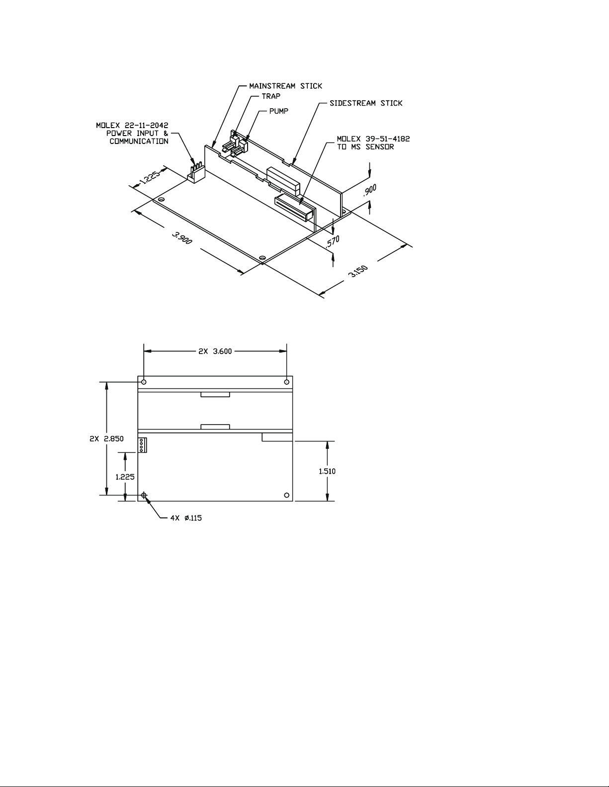
Duet CO2Module OEM Implementation Manual
Duet Dimensions and Connector Locations
Page 60 Confidential Welch Allyn OEM Technologies
Page 61

Duet CO2Module OEM Implementation Manual
Welch Allyn Mainstream Sensor II Specifications
PHYSICAL SPECIFICATIONS
Dimensions
0.75 in L × 1.35 in W × 1.00 in H (19.5 mm × 34.29 mm × 25.4
mm)
Volume 1.01 in3(16.59 cm3)
Weight < 18.5 grams excluding cable
Cable Length 10 ft / +1.0 in / -4.0 in (3.05 m / +2.5 cm/-10.2 cm)
PERFORMANCE SPECIFICATIONS
Sensor Type Mainstream (“on airway”)
Measurement Technique Non-dispersive infrared ; single beam; single frequency;
ratiometric
CO2Measurement Range 0 – 99 mmHg
CO2Accuracy
a
+2 mmHg(0 – 40 mmHg CO2)
+
5% reading(41 – 76 mmHg CO2)
10% reading(77 – 99 mmHg CO2)
+
Start up Time System dependent
Calibration no routine calibration required
Calibration Stability < 1% outside accuracy spec after 12 months of continuous use
Response Time 30 msec typical
60 msec max
Housing Temperature 42oC nominal
Power Consumption < 2.0 W quiescent across operating temp range
ENVIRONMENTAL SPECIFICATIONS
Temperature 10oC-40oC operating
o
-20
C – 60oC storage
Humidity 0 – 95% operating (non-condensing)
0 – 95% storage (non-condensing)
Barometric Pressure 0 – 16,000 ft equiv. operating
0 – 45,000 ft equiv. storage
Vibration Limit 5 Hz – 35 Hz; 0.015 in peak to peak 35 Hz – 100 Hz; 1 g acceleration
/operating
10 Hz – 500 Hz; 3 g acceleration /storage
Shock Limit 100 g for 4 msec
(3 successive ½ sine wave shocks each of 3 mutually exclusive
perpendicular axes; 9 shocks)
Drop Limit 6 ft floor drop operating
(concrete or equiv.; random orientation)
a Accuracy specification is based upon the following standard airway conditions: sensor 42oC; airway
adapter temperature 33
balance air; fully hydrated at 33
o
C; water vapor pressure 38 mmHg; standard gas mixture equals CO2in
o
C; barometric pressure 760 mmHg; airway flow rate 60 cc/min.
Welch Allyn OEM Technologies Confidential Page 61
Page 62

Duet CO2Module OEM Implementation Manual
Adult/Pediatric Single-Use Airway Adapter Specifications
PHYSICAL SPECIFICATIONS
Overall Dimensions 2.04"L.x 0.88"W x 1.14"H
(5.2cm L x 2.24cm W x 2.9cm H)
Contributory Dead Space 6cc (6ml)
Fittings: Male O.D. 15mm, per ISO 5356-1 and ASTM F1054
Female I.D. 15mm, per ISO 5356-1 and ASTM F1054
Resistance: See Figure A
Nominal Weight: 4.8g
Material: Polycarbonate resin and sapphire
Pressure Leak Tested at: 15psi
Environmental Conditions
Ambient Shipping/Storage:
Temperature
Relative Humidity
Barometric Pressure
Ambient Operating Conditions:
Temperature
Relative Humidity
Barometric Pressure
Note: This airway adapter is designed for a maximum flow of 120 l/min. This airway
adapter is not designed for reuse on another patient.
-4° to 140° F (-20° to 60° C)
10-95% RH, non-condensing
795mmHg to 375mmHg (-1300ft to 45000ft)
50° to 140° F(10° to 60° C)
10%-95%RH, non-condensing
795mmHg to 375mmHg (-1300ft to 45000ft)
Pressure Drop
(cm H
5
4.5
4
3.5
3
2.5
2
1.5
1
0.5
0
0 10 20 30 40 50 60 70 80 90 100 110 120
Flow (Liters/min)
0)
2
Figure A
Average Pressure Drop Across the Adult Airway Adapter
Page 62 Confidential Welch Allyn OEM Technologies
Page 63

Duet CO2Module OEM Implementation Manual
Low Dead Space Single-Use Airway Adapter Specifications
PHYSICAL SPECIFICATIONS
Overall Dimensions 2.04"L.x 0.88"W x 1.14"H
(5.2cm L x 2.24cm W x 2.9cm H)
Contributory Dead Space <1cc (1ml)
Fittings: Male O.D. 15mm, per ISO 5356-1 and ASTM F1054
Female I.D. 15mm, per ISO 5356-1 and ASTM F1054
Resistance: See Figure B
Respiration Rate 0 to 150 bpm
Nominal Weight: 4.8g
Material: Polycarbonate resin and sapphire
Pressure Leak Tested at: 15psi
Environmental Conditions
Ambient Shipping/Storage:
Temperature
Relative Humidity
Barometric Pressure
Ambient Operating Conditions:
Temperature
Relative Humidity
Barometric Pressure
Note: This airway adapter is designed for a maximum flow of 30 l/min. This airway
adapter is not designed for reuse on another patient.
-4° to 140° F (-20° to 60° C)
15-95% RH, non-condensing
795mmHg to 375mmHg (-1300ft to 45000ft)
50° to 140° F(10° to 60° C)
15%-95%RH, non-condensing
795mmHg to 375mmHg (-1300ft to 45000ft)
Pressure Drop
0)
(cm H
2
10
8
6
4
2
0
0 5 10 15 20 25 30
Flow (Liters/min)
Figure B
Average Pressure Drop Across the Low Dead Space Airway Adapter
Welch Allyn OEM Technologies Confidential Page 63
Page 64

Duet CO2Module OEM Implementation Manual
Adult/Pediatric Multi-Use Airway Adapter Specifications
PHYSICAL SPECIFICATIONS
Overall Dimensions 2.04"L.x 0.88"W x 1.14"H
(5.2cm L x 2.24cm W x 2.9cm H)
Contributory Dead Space 6cc (6ml)
Fittings: Male O.D. 15mm, per ISO 5356-1 and ASTM F1054
Female I.D. 15mm, per ISO 5356-1 and ASTM F1054
Resistance: See Figure C
Respiration Rate 0 to 150 BPM
Nominal Weight: 4.8g
Material: Polysulfone resin, aluminum and sapphire
Pressure Leak Tested at: 15psi
Sterilizing Method: Steam autoclave
Environmental Conditions
Ambient Shipping/Storage:
Temperature
Relative Humidity
Barometric Pressure
Ambient Operating Conditions:
Temperature
Relative Humidity
Barometric Pressure
Note: This airway adapter is designed for a maximum flow of 120 l/min. This airway adapter is
designed to be sterilized via steam autoclave only. Do not exceed 250° F (120° C)
(14.7PSIG). Designed to withstand a minimum of 20 sterilization cycles.
-4° to 140° F (-20° to 60° C)
15-95% RH, non-condensing
795mmHg to 375mmHg (-1300ft to 45000ft)
50° to 140° F(10° to 60° C)
15%-95%RH, non-condensing
795mmHg to 375mmHg (-1300ft to 45000ft)
Pressure Drop
5
4.5
4
3.5
3
2.5
2
1.5
1
0.5
0
0 10 20 30 40 50 60 70 80 90 100 110 120
Flow (Liters/min)
(cm H
0)
2
Figure C
Average Pressure Drop Across the Adult Airway Adapter
Page 64 Confidential Welch Allyn OEM Technologies
Page 65

Duet CO2Module OEM Implementation Manual
Software Procedures
CRC Code Calculation
The 8 bit CRC code is based on the CCITT/CRC polynomial which uses the conventional right shifting
(high to low) method. The polynomial is:
G(x) = x^8 + x^7 + x^2 + 1
The feedback constant is 0xA1 (hex). CRC values are initialized to 0xFF (hex).
The CRC update value is implemented by a table look up scheme. The following is an
implementation example in ‘C’ language.
Usage:
#define updatecrc_8(value,crc) (crc_table_8[value^crc])
#define MAX_SIZE 23 /*choose any size*/
unsigned char crc_table_8[256];
unsigned char data[MAX_SIZE]; /*data to be CRC checked*/
unsigned char calc_crc(char data,int n)
{
unsigned char crc;
/*make_table_8( );*/ /*do this at least once*/
crc=0xFF;
for(i=0;i<n;i++){
crc=updatecrc_8(data[i],crc);
}
return(crc);
}
Welch Allyn OEM Technologies Confidential Page 65
Page 66

The table can be created by the following code:
void make_table_8(void)
{
const unsigned char feedback_8=0xA1;
unsigned char crc;
unsigned int i;
unsigned char j, tmp;
for (i =0; i < 256; i++) {
tmp = i;
crc = 0;
for (j = 0; j< 8; j++) {
if (( tmp & 1) ^ (crc & 1)) crc = (crc >> 1) ^ feedback_8;
else crc >>= 1;
tmp >>= 1;
}
crc_table_8[i] = crc;
}
}
CRC Example:
Duet CO2Module OEM Implementation Manual
Using the following Waveform Byte String as an example:
= 37.50 mmHg
CO
2
{STX} “W” xx yy CCITT/CRC {ETX} waveform byte string
0x25 0x80 0x79 {STX}W258079{ETX}
02h 057h 0x25 0x80 0x79 03h with the actual byte stream as:
"{STX}W258079{ETX}"
In our example, 057h represents a single character, the ASCII letter "W". 0x25 represents the
resulting value of the ASCII HEX representation of the parameter value. Thus 0x25 is actually
transmitted as 32h (ASCII letter "2") followed by 35h (ASCII letter "5").
The CRC check should be performed at a very low level within the host's software. A CRC of the
actual transmitted bytes excluding the check byte (which is sent as 2 ASCII HEX characters)
should be performed by the host on the 8 bit binary numbers retrieved from the Asynchronous
UART starting with the character immediately following the {STX} and ending with the character
immediately preceding the two ASCII HEX check characters.
The CRC is initially seeded with 0xFF before the CRC is computed. This is a very common
practice.
Page 66 Confidential Welch Allyn OEM Technologies
Page 67

Duet CO2Module OEM Implementation Manual
O2/N2O/Desflurane Compensation
The presence of oxygen (O2), nitrous oxide (N2O), and desflurane at elevated concentrations affects
the measurement of CO
value during the presence of these interfering agents at high levels
The Duet module provides mathematical compensations that utilize midpoint correction factors for
interfering agents such as Oxygen (O
be manually enabled by the user to compensate the ETCO
interfering agents at high levels. As the concentrations of interfering agents move away from the
midpoint values, the correction error becomes greater.
The variables and correction equations are summarized in this table.
concentration. O2,N2O and desflurane compensations correct the ETCO
2
), Nitrous Oxide (N2O) and desflurane. The compensations may
2
value during the presence of these
2
2
O
Correction N2O/Desflurane Correction
2
OFF OFF
ON OFF
OFF ON
ON ON
Operating Conditions
≤ 50%, no N2O
O
2
> 50%, no N2O
O
2
≤ 50% and N2O or desflurane ≥ 12%
O
2
> 50% and N2O or desflurane ≥ 12%
O
2
The O2/N2O/desflurane compensations are enabled/disabled by the following Function Enable/Disable
commands.
Compensation Function Enable Command
O2compensation OFF <Q000>
O2compensation ON <Q001>
N2O compensation OFF <Q010>
N2O compensation ON <Q011>
Desflurane compensation OFF <Q020>
Desflurane compensation ON <Q021>
Welch Allyn OEM Technologies Confidential Page 67
Page 68

Duet CO2Module OEM Implementation Manual
Percent CO2 Calculation
It is necessary to convert the CO2display from mmHg to percent CO2in order to compare the
measurement to a calibrated gas, usually marked in percent CO
where the preferred units of measure is % CO
pressure (mmHg) CO
the corresponding percentage. Typically, calibrated gas measurement is a
2
.) The Host system is responsible to convert partial
2
steady state measurement, so updated breath data is not necessary. Also, calibrated gasses are dry
gas, therefore the water vapor and BTPS compensations should be disabled by the Host in those
instances where dry gas readings are made.
INITIALIZE BREATH DATA UPDATE RATE <O00>
ê
REQUEST AMBIENT BAROMETRIC PRESSURE <C22>
ê
DIVIDE ETCO
(IN MMHG) VALUE BY AMBIENT BAROMETRIC PRESSURE (IN MMHG)
2
. (There are other user environments
2
Software Upgrade
Download to FLASH Memory
To load new executive code into the Duet Module via the serial port of a PC, use the inject.exe
application. Welch Allyn OEM Technologies will provide the application when software upgrades are
required. The source code was written in C programming language and consists of four modules:
heart.c, syringe.c, needle.c and serial.c. Inject.exe is designed to run from the DOS command line as
there are timing issues involved with loading the boot code. Inject does not run well under W indows. It
is assumed that an operational DUET Module is connected to a viable serial port and that power is
supplied to the DUET Module for the download to function properly.
The DUET Module is referred to as the “module” in the following section.
Command Line Parameters
The command line parameters, or switches, must be set for inject.exe to work. Because of this, it is
easiest to invoke inject.exe from a batch file. The switches are listed in the following table.
Switches Description
-Fx Inject Fast, where x =
0: the agent is transmitted at 2400 baud
1: the executive loader code, or agent, is sent to the module at
19200 baud
-Cfilename.ext File name of executable code that is to be loaded into the module.
The file is expected to be in a Motorola S1:S9 format which is
explained at the end of this section.
-Rfilename.ext File name that contains the values to be loaded into the registers to
configure the 68HC11.
Page 68 Confidential Welch Allyn OEM Technologies
Page 69

Duet CO2Module OEM Implementation Manual
Switches Description
-Bfilename.ext File name that contains the agent. This file is expected to be in the
Motorola S1:S9 format.
-Mfilename.ext File name that contains the miniboot agent. This file is expected to
be in the Motorola S1:S9 format.
-Vx Verbose mode, where x =
0: no reports of progress
1: every step of the loading process is displayed on the screen
-Lx Load boot loader, where x =
0: the boot loader is assumed to be in memory
1: the boot loader is loaded
-Ax Binary mode, where x =
0: Executive image will be sent in ASCII S1:S9 format
1: the executive image is sent to the module in binary mode
instead of ASCII S1:S9 format. This reduces the number of
characters sent to the module to approximately one-half or the
original.
-Wx Load agent, where x =
0: load the agent into the module at 9600 baud
1: load the agent into the module at 38400 baud. When -W1 is
used in conjuction with –A1, the agent is loaded as fast as is
possible.
-Px Com port, where x =
1: com port 1 is used to communicate to the module
not 1: com port 2 is used
EXAMPLE
-INJECT -V1 -Rregs.s0 -Bbooter.0 -F1 –Cscud.mot -A0 -L1 -W 1 – P2
Loads the file regs.s0 into the configuration registers of the Duet’s 68HC11. The file booter.0 is loaded
into the module to accept the executive image. The file scud.mot is loaded in as the executive image.
The executive is loaded in the binary mode at 38400 baud. The booter is loaded into memory at 19200
baud using Com2.
Welch Allyn OEM Technologies Confidential Page 69
Page 70

Operation
The following sequence loads the new executive code.
INITIALIZE SERIAL PORT
ê
LOAD THE BOOT LOADER
ê
CONVERT EXECUTIVE LOADER CODE TO BINARY
ê
LOAD BOOT AGENT
ê
LOAD REGISTER FILE IMAGE, IF SPECIFIED
ê
LOAD EXECUTIVE FILE
INITIALIZE THE SERIAL PORT
LOAD THE BOOT LOADER
Duet CO2Module OEM Implementation Manual
If the –L1 switch is issued, the file specified by the –B switch is fetched from disk and loaded into
memory. If this file is not specified or does not exist, an error is issued and the program terminates.
CONVERT EXECUTIVE LOADER CODE TO BINARY
The file pointed to by the –M switch is pulled into memory and converted to binary. The module resets
into bootstrap mode by sending a continuous break signal to the module for a period of 750 msec. The
break signal is released and the module is given 250 msec to respond by transmitting a break signal
back to the PC. If the module responds within the 250-msec (What’s the edit?) period, the PC begins
the process of loading the boot agent. If this break signal is not received within the 250-msec (What’s
the edit?) period, the program issues an error and exits.
LOAD BOOT AGEN T
In order for the module to determine the baud rate at which the agent is being loaded, the module looks
at the first char received.
If the –F switch is issued with a 0xf0, the boot agent is loaded at a maximum speed of 19200 baud. If
the –F switch is not issued; a single 0xFF is transmitted at 2400 baud to indicate the data is to be sent
at the respective baud rates.
Once the first char is transmitted, the boot agent must be immediately sent as a continuous serial
stream at the specified baud rate. Each char received by the module is subsequently echoed back to
the PC. If the char is sent and an echo is not registered within 100 msec, an error is assumed to have
occurred and the program issues an error and exits.
After the boot agent is loaded, the PC changes to 9600 baud and looks for a “
” char to indicate that the
*
boot agent is running on the module. The program waits a maximum of 100 msec to receive this char
and issues an error and exits if not received within this period.
LOAD REGISTER FILE IMAGE, IF SPECIFIED
The register file image is loaded into the module.
Page 70 Confidential Welch Allyn OEM Technologies
Page 71

Duet CO2Module OEM Implementation Manual
LOAD EXECUTIVE FILE
The boot agent moves its buffer memory to 0x1000.
If –W1 switch is issued, the communication baud rate must be changed to 38400 baud. To accomplish
this, the PC issues a register write command to the module. The registers that are written to in the
module are baud rate dividers. This command is sent at the prevailing baud rate. Both registers must
be sent in one command since the changes are invoked immediately upon receipt. The inject.exe
program then waits approximately 60 msec for the module to respond. After the module responds to
the baud rate change, the executive file is opened and loaded into the module. If the module does not
respond within 60 msec, the program will time out, issue an error, and exit.
If the –A1 switch is issued; each line of the S0:S9 file is read into memory and converted to a binary
image before it is sent to the module.
Motorola S Record Format
Records Description
S0 Control record that is used to send commands to the boot agent. S0 records
have the following format.
00 write byte to address (data1)(data2) with byte (data3)
01 read from address (data1)(data2)(data3) bytes
02 erase FLASH (data1) = aa, (data2) = 55, (data3) = 80
03 move BUFFER to address (data1)(data2)
04 which byte to check when erasing FLASH
05 reset FLASH device
06 write a string of bytes to local EEPROM
S1 Motorola standard record that is assumed to be going into FLASH.
S3 Record that is sent in binary format. This loads code almost twice as fast as
normal mode. To create a binary record, a standard S1 record is read in by
the PC. The PC then sends the DUET Module the S3 identifier. Each pair of
ASCII bytes in the S1 record are converted to a single byte and then sent to
the DUET Module.
S9 Record that is the standard terminator and transfers control to the address
specified.
Welch Allyn OEM Technologies Confidential Page 71
Page 72

Duet CO2Module OEM Implementation Manual
Page 72 Confidential Welch Allyn OEM Technologies
Page 73

Duet CO2Module OEM Implementation Manual
g
g
g
g
g
EEPROM Maps
System EEPROM Map Table
Word
(hex)
00 16 bit CRC word/range: 01h to 37h
01 LSB
02 CO2main processor board serial #/range: 0000h to FFFFh
03 LSB Hardware version
04 Barometer gain, unsigned integer/range: 0F00h to 1300h
05 Barometer offset, unsigned integer/range: -8000h to 7FFFh
06 LSB
07 LSB
08 LSB
09 MSB Pump flow deviation from threshold in cc/min
0A LSB
0B LSB Pump flow failure timeout
0C LSB
0D LSB
0E IR source gain constant, unsigned integer/range: 0E00h to 11FFh
0H IR source offset constant, signed integer/range: -8000h to 7FFFh
10 LSB
11 LSB Desflurane compensation
12 LSB
13 LSB
14 LSB &
15 LSB
16 LSB
17 LSB
Register Description
EEPROM revision #
MSB
MSB
MSB
MSB
MSB
MSB
MSB
MSB
MSB
MSB
MSB
MSB
MSB
MSB
OEM specific code
Pump flow control proportional constant/range: 00h to FFh
Pump flow control integral constant/range: 00h to FFh
Pump flow control derivative constant/range: 00h to FFh
Pump flow control PID SCALE factor constant/ran
Pump flow control initial flow rate
Pump output limit/ran
Occlusion timeout before high pump flow
High pump flow time
Pressure thresholdgain/range: 00h to FFh
Pressure threshold offset, si
Occlusion pump vacuum timeout
Occlusion pump vacuum control & pressure re
O2compensation
N2O compensation
MS water compensation
SS water compensation
MS BTPS compensation
SS BTPS compensation
SS baseline compensation
CO2waveform data filter/0 = none, 1 = 3 pt (25-50-25), 2 = 3 pt (30-40-30)
filter
ETCO
2
RR filter
2
filter
InsCO
Maximum fast heat PWM
Maximum normal heat PWM
e: 00h to FFh
e: 0 to 255
ned integer/range: -80h to 7Fh
ulated in mmH
Welch Allyn OEM Technologies Confidential Page 73
Page 74

Duet CO2Module OEM Implementation Manual
(
)
y
j
Word
(hex)
18 LSB
19 Start_up flags
1A Default breath update
1B Dark phase pulse time in 1 microsecond ticks
1C Pump overflow timer in 200 msec ticks/ffff = OFF
1D Pump occlusion warning timer in 200 msec ticks/ffff = OFF
1E Pump occlusion error timer in 200 msec ticks/ffff = OFF
1F Water trap missing timer in 200 msec ticks/ffff = OFF
20 Optical occlusion first warning in 1.221 mV steps/ffff = OFF
21 Optical occlusion second warning in 1.221 mB steps/ffff = OFF
Register Description
Minimum heat delta during warm up
MSB
Heater failure timer
Mainstream Sensor EEPROM Map Table
Word
hex
00 LSB &
01 LSB
02 Serial #
03 Gain constant
04 LSB
05 LSB
06 LSB
07 MSB Minor revision #
08 Real-time register #1
09 Real-time register #2
0A Real-time register #3
0B CRC in words/range: 00h to 07h and 0Ch to 3Fh
0C Referencegas cell phase timer
0D IR source current
0E Reserved
0F Reserved
10 Next user calibration gain constant
11 LSB
12 User calibration date/time stamp
13 – 15 Next user calibration data (10h, 11h and 12h formats)
16 – 18 Next user calibration data (10h, 11h and 12h formats)
3D – 3F Next user calibration data (10h, 11h and 12h formats)
Register Description
Checksum/range: 01h to 07h
MSB
EEPROM revision #
MSB
MSB
MSB
MSB
MSB
OEM specific code
Linearityconstant
Offset constant
Temperature compensation constant
Sensitivit
Bias adjustment constant
User calibration pointer
Open phase timer
User calibration offset constant
User calibration bias ad
constant
ustment constant
Page 74 Confidential Welch Allyn OEM Technologies
Page 75

Duet CO2Module OEM Implementation Manual
Error Messages & Recovery
This appendix lists and defines the Duet CO2Module status codes. Recovery attempts are suggested if
the status indicates a fault condition. The fault conditions are grouped in three categories.
§ Advisories - non-fatal conditions, which do not halt module operation.
§ Soft faults – conditions which interrupt module operation, including transmission of CO
waveform and breath data packets, until the fault is cleared. The module can accept
commands in the soft fault state..
§ Hard faults – Halt Module operation and prevent the module from accepting commands.
A Host reset can be used in an attempt to clear hard faults.
Recovery attempts may include the host initiating a reset.
• Reset – If the host holds the receive data line in a break condition for greater than 10 msec,
but less than 500 msec, the microprocessor is forced into reset.. After a reset, the module
returns to its EEPROM default settings and starts in the sidestream fault mode. The module
can respond to host communication 2 seconds after a hard reset.
Advisories
Mainstream/Sidestream
Status
Message Code
(hex)
00 status ok
01 communication error
02 host command with invalid data
03 unprotected operation violation
10 warm up in progress
11 CO2sensor start up in progress
13 signal low
Definition Possible Causes
• host/module communication is in error
• identifier is inconsistent with data
• host attempts to invoke a protected
operation
• status requested during preliminary warm
up phase of mainstream sensor
• status requested during CO
chopper motor start up phase
• obstructed airway adapter
• airway adapter windows not clean
• CO
sensor windows not clean
2
• faulty airway adapter/CO
2
sensor
2
sensor
2
Welch Allyn OEM Technologies Confidential Page 75
Page 76

Duet CO2Module OEM Implementation Manual
Status
Definition Possible Causes
Message Code
(hex)
14 signal very low
15 barometric pressure offset too
large
19 dark phase signal noisy
1A open phase signal saturated
27 calculation error
10h, Warm Up in Progress (mainstream only)
Status is requested during the primary stage of mainstream sensor warm up. It is not an
indication of failure but an indication that the mainstream sensor is working to achieve
operating temperature. During the preliminary warm up phase, the mainstream sensor
reaches the “near final” temperature and progresses to the start up phase of operation. Once
start up conditions are met, the mainstream sensor returns to complete the warm up phase.
This code is sent only during the preliminary warm up phase.
• obstructed airway adapter
• airway adapter windows not clean
• CO
• faulty airway adapter/CO
sensor windows not clean
2
2
sensor
• faulty barometric transducer
• electrical interference
faulty sensor
• faulty sensor
• CO
or breath measurement calculation
2
error
11h, CO2Sensor Start up in Progress
Status is requested during the mainstream or sidestream CO2sensor chopper motor start. It is
not an indication of failure but an indication that the chopper motor is in the start up phase.
Once operating speed is reached and the sync signal is captured, the mainstream or
sidestream CO
sensor automatically progresses to the next phase of operation.
2
13h, Signal Low
IR detector voltage measured during the reference gas cell phase of the chopper wheel
rotation is less than the lower signal limit. CO
despite the advisory. Host may want to disregard this level and only report the next level, or
advisory (refer to 14h).
Action (mainstream)
• Clear airway adapter of obstructions by removing the airway adapter from the
ventilator circuit. Rinse with water and air dry.
• Clean CO
• Make sure the CO
sensor housing windows.
2
sensor is completely seated on the airway adapter and that the
2
sensor is in the upright position on the circuit.
• Replace the airway adapter.
• If available, replace the CO
Action (sidestream)
Verify system not exposed to excessive contamination.
sensor.
2
waveform and breath data packets are available
2
Page 76 Confidential Welch Allyn OEM Technologies
Page 77

Duet CO2Module OEM Implementation Manual
15h, Barometric Pressure Offset Too Large (sidestream only)
Difference between the two pressure transducer values is greater than the upper barometric
offset limit when the pump is OFF.
Action Replacing one or both of the pressure transducers.
19h, Dark Phase Signal Noisy
IR detector voltage measured during the dark phase of the chopper wheel rotation is greater
than the upper signal limit. This is caused by electrical noise on the signal. CO
breath data packets are available despite the advisory.
Action Relocating the Duet CO
equipment. If available, replace the CO
Module and the mainstream sensor away from electrical
2
sensor.
2
1Ah, Open Phase Signal Saturated
IR detector voltage measured during the open phase of the chopper wheel rotation is greater
than the upper signal limit. CO
waveform and breath data packets are available despite the
2
advisory.
Action If available, replace the CO
sensor.
2
waveform and
2
27h, Calculation Error
Error detected when calculating CO2or breath measurement.
Pneumatic System
Status
Message Code
16 no Water trap
17 Water trap or cannula
18 exhaust occlusion or
Definition Possible Causes
occlusion
pneumatic leak
• Water trap not properly installed
• misaligned Water trap receiver switch
• faulty receptacle/Water trap receiver
switch
• obstructed Water trap/cannula
• sample line kink
• obstructed internal pneumatic component
• obstructed host exhaust port
• exhaust tubing kink
• faulty/disconnected pump
Welch Allyn OEM Technologies Confidential Page 77
Page 78

16h, No Water trap
The Duet CO2Module does not detect a Water trap properly inserted into the Water trap
receiver. The Duet CO
Module inhibits CO2waveform and breath data packets unless the
2
Water trap is only temporarily disconnected. If reinsertion occurs within 30 seconds from
disconnect, the Duet CO
seconds, the Duet CO
Module resumes normal operation. If not connected within 30
2
Module reverts to standby mode and halts the transmission of data
2
packets. When the advisory is cleared, a new measurement mode command is required to
resume data packet transmission unless the module was in the auto run mode. In this case,
measurement resumes. The sidestream pump is disabled during this advisory.
Action Reinserting the Water trap into the Water trap receiver. If this does not clear the
advisory, the internal Water trap receiver switch may be misaligned or faulty.
17h, Water trap or Cannula Occlusion
Low flow and high vacuum conditions are detected in the pneumatic system. CO2waveform
and breath data packets are available despite the advisory. The Duet CO
clear obstructions while reporting these conditions by increasing the pump speed. If the
obstruction is not cleared after 5 seconds, the module decreases the pump speed and holds
vacuum for an additional 15 minutes. If the obstruction is not cleared after 15 minutes, the Duet
CO
Module reverts to standby mode.
2
Action clearing any obstructions in the Water trap and cannula. Straighten any kinks in the
cannula tube. If the error persists, isolate the obstruction to the Water trap or the cannula by
briefly disconnecting the cannula from the Water trap. If the cannula is the source of the
blockage, the fault is corrected. If the fault persists, replace the Water trap and/or the cannula.
Duet CO2Module OEM Implementation Manual
Module attempts to
2
18h, Exhaust Occlusion or Pneumatic Leak
Low flow and normal vacuum conditions are detected in the pneumatic system. CO2waveform
and measurement data packets are available despite the advisory. Normal measurement
resumes once the advisory is cleared.
When this condition occurs, the Duet CO
Module increases pump speed to a
2
maximum and runs indefinitely until the condition is cleared.
Action Clear any obstructions in the exhaust tube and screen. Straighten any kinks in the
exhaust tube. If the condition persists, verify that the pump is operating by resetting the mode
and listening for audible pump operation noise.
Soft Faults
Soft faults are conditions that halt module operation until the condition is cleared. CO2waveform and
breath data packet transmission is halted until the fault is cleared. The module can accept commands
in this error state.
Page 78 Confidential Welch Allyn OEM Technologies
Page 79

Duet CO2Module OEM Implementation Manual
Sensor Faults
CO2sensor faults are conditions that result in shutting down the sensor. A CO2sensor shutdown stops
the chopper motor and turns off the lamp, the heater in mainstream operation and the pump in
sidestream operation
To clear a sensor fault Implement one of the following.
• A mainstream sensor disconnect and reconnect if mainstream operation.
• A software reset followed by a new host command. If the module does not accept the command, a
hard reset is required.
• A hard reset by holding the receive data line in a break condition for 10 msec to 500 msec. A hard
reset forces the microprocessor to enter the boot mode once the condition is released. On power
up, the microprocessor is held in reset for about 100 msec after the supply voltage rises above 4.5
V.
Sensor faults are listed in the following table.
Status
Definition Possible Causes
Message Code
14 CO2sensor signal very low
50 CO2sensor disconnect
51 CO2sensor manufacturer ID
mismatch
60 CO2sensor EEPROM error in
revision #
61 CO2sensor EEPROM error in
checksum
65 CO2Sensor EEPROM error in
read or write operation
66 CO2sensor EEPROM error in
CRC code
70 CO2sensor temperature too
high
71 CO2sensor temperature too
low
72 CO2sensor warm up error
73 CO2sensor heater output error
78 CO2sensor motor speed out of
range
79 CO2sensor motor start error
7B CO2sensor signal unable to
synchronize
7E CO2sensor IR source error
• obstructed airway adapter
• airway adapter windows not clean
• CO
• faulty airway adapter/CO
sensor windows not clean
2
2
sensor
• loose sensor connector
• faulty sensor
• faulty Nicolay receptacle/flex circuit
• another company’s sensor
• faulty sensor EEPROM
• incompatible/invalid sensor EEPROM
revision #
• faulty sensor EEPROM
• invalid sensor EEPROM checksum
• faulty sensor EEPROM
• invalid read/write to sensor EEPROM
• faulty sensor EEPROM
• invalid sensor EEPROM CRC code
• faulty sensor EEPROM
• sensor exposure to excessive heat source
• faulty sensor
• sensor exposure to excessive cold source
• faulty sensor
• faulty sensor
• faulty sensor
• faulty sensor or sensor cable
• faulty sensor or sensor cable
• faulty sensor or sensor cable
• faulty sensor
Welch Allyn OEM Technologies Confidential Page 79
Page 80

Duet CO2Module OEM Implementation Manual
14h, CO2Sensor Signal Very Low
IR detector voltage measured during the reference gas cell phase of the chopper wheel
rotation is below the preset threshold. Transmission of CO
is halted until the advisory is cleared. The Duet CO
Module remains in the measurement
2
mode despite the condition.
Action Following instructions for 13h fault code.
50h, CO2Sensor Disconnect
Duet CO2Module does not detect an attached CO2sensor.
Action If mainstream operation, try a different sensor. If the fault persists when a CO
is connected, check if the sensor connector is loose by reseating the connector.
51h, CO2Sensor Manufacturer ID Mismatch (mainstream only)
Mainstream sensor’s ID stored in the EEPROM does not match the correct OEM specific
code.
Action If mainstream operation, try a different sensor and issue a new measurement mode
command.
waveform and breath data packets
2
sensor
2
60h, CO2Sensor EEPROM Error/Revision #
Revision # read from the CO2sensor EEPROM is invalid.
Action Check that the revision data is in the 1.xx format. If mainstream operation, try a
different sensor and issue a new measurement mode command.
61h, CO2Sensor EEPROM Error/Checksum
Checksum read from the CO2sensor EEPROM is invalid.
Action If mainstream operation, try a different sensor and issue a new measurement mode
command.
65h, CO2Sensor EEPROM Error/Read/Write
A read or write error to the CO2sensor EEPROM has occurred.
Action If mainstream operation, try a different sensor and issue a new measurement mode
command.
66h, CO2Sensor EEPROM Error/CRC Code
CRC code read from the CO2sensor EEPROM is invalid.
Action If mainstream operation, try a different sensor and issue a new measurement mode
command.
Page 80 Confidential Welch Allyn OEM Technologies
Page 81

Duet CO2Module OEM Implementation Manual
70h, CO2Sensor Temperature Too High
During measurement
• if mainstream operation, the mainstream sensor temperature is greater than 48
more than 30 seconds.
• if sidestream operation, the CO
2
30 seconds.
Action Check for exposure of the CO
includes the host system and the electronics in close proximity to the CO
remove the source. If mainstream operation, try a different sensor and issue a new
measurement mode command.
71h, CO2Sensor Temperature Too Low
During measurement
• if mainstream operation, the mainstream sensor temperature is less than 36
than 30 seconds.
• if sidestream operation, the CO
2
seconds.
Action Check for exposure of the CO
includes the host system and the electronics in close proximity to the CO
remove the source. If mainstream operation, try a new sensor and issue a new measurement
mode command.
o
Cfor
sensor’s temperature is greater than 60oC for more than
sensor to an excessive external heat source. This
2
sensor. If identified,
2
o
Cformore
sensor’s temperature is less than 5oC for more than 30
sensor to an excessive external cold source. This
2
sensor. If identified,
2
72h, CO2Sensor Warm Up Failure (mainstream only)
Mainstream sensor warm up rate is less than 1oC per minute and is not able to reach the
required operating temperature of 42
o
C. The module discontinues the warm up phase and
waits for a new command.
Action If the fault persists, check for a faulty mainstream sensor cable. Replace the cable, if
possible. If the fault persists, check for exposure of the mainstream sensor to an excessive
external heat or cold source. This may include the monitor or the electronics in close proximity
to the mainstream sensor. If identified, remove the source. If mainstream operation, try a new
sensor and issue a new measurement mode command.
73h, CO2Sensor Heater Output Error (mainstream only)
A heater output overload condition exists.
Action Inspect for damage to the mainstream sensor cable and replace if possible. If
mainstream operation, try a different sensor and issue a new measurement mode command.
78h, CO2Sensor Motor Speed Out of Range
CO2sensor’s chopper motor has too much or too little power to keep the motor speed in the
allowable range for more than 60 seconds. A CO
2
Action If mainstream operation, try a different sensor and issue a new measurement mode
command. If sidestream operation, send a new host measurement mode command.
sensor shutdown occurs.
Welch Allyn OEM Technologies Confidential Page 81
Page 82

79h, CO2Sensor Motor Start Error
CO2sensor’s chopper motor does not start.
Action If mainstream operation, try a different sensor and issue a new measurement mode
command. If sidestream operation, send a new host measurement mode command.
7Bh, CO2Sensor Signal Unable to Synchronize
After enabling the IR source, the software attempts to determine which phase of chopper
wheel rotation the CO
sensor is in. If the software is unable to detect, or synchronize to the
2
phase after 60 seconds, this fault occurs and a CO
• Action If mainstream operation, try a different sensor and issue a new measurement mode
command. If sidestream operation, send a new host measurement mode command.
7Eh, CO2Sensor IR Source Error
IR source current is out of range when the source is active.
Action If mainstream operation, try a different sensor and issue a new measurement mode
command. If sidestream operation, send a new host measurement mode command.
Duet CO2Module OEM Implementation Manual
sensor shutdown occurs.
2
System Faults
The majority of system faults are conditions that are internal to the module and not caused by the host.
The exceptions are 81h, 82h, 84h and 85h.
To clear most system faults With the exception of 81h, 82h, 84h and 85h, do a hard reset.
System faults are listed in the following table.
Status
Message Code
40 watchdog error
44 system EEPROM error in CRC
46 system FLASH ROM error in
47 system communication error
4B/4C system RAM error
4D system FLASH ROM error in
4E stack overflow error
4F system SW error in main
53 no mainstream daughter board
57 no sidestream daughter board
80 pump failure
Definition Possible Causes
• watchdog timeout
• invalid system EEPROM CRC code
code
• invalid FLASH ROM CRC code
CRC code
• faulty FLASH ROM chip
• microprocessor failure to complete task
• malfunctioning real-time operating system
• faulty system internal RAM
• invalid system internal FLASH data
checksum
• faulty FLASH ROM chip
• stack usage error
•
program
• faulty/absent mainstream daughter board
• faulty interface to mainstream daughter
board
• faulty/absent sidestream daughter board
• faulty interface to sidestream daughter
board
• faulty pump
• pneumatics disconnected
Page 82 Confidential Welch Allyn OEM Technologies
Page 83

Duet CO2Module OEM Implementation Manual
Status
Message Code
81 unexpected reverse flow
82 unexpected forward flow
84 barometric pressure too high
85 barometric pressure too low
40h, Watchdog Error
Watchdog timeout has occurred.
44h, System EEPROM Error/CRC Code
CRC code read from the system EEPROM is invalid.
46h, System FLASH ROM Error/CRC Code
CRC code read from the system FLASH ROM is invalid.
Definition Possible Causes
• Water trap/cannula/exhaust tubing not
properly connected
• Water trap/cannula/exhaust tubing not
properly connected
• host system operating above 790 mmHg
(1,150 ft below sea level)
• faulty barometric transducer
• host system operating below 408 mmHg
(15,000 ft above sea level)
• faulty barometric transducer
47h, System Communication Error
4Bh/4Ch, System RAM Error
4Dh, System FLASH ROM Error/Checksum
Checksum read from the system FLASH ROM is invalid.
4Eh, Stack Overflow Error
An error in stack usage occurred.
4Fh, System SW Error/Main Program
Main SW program is exited.
57h, No Sidestream Daughter Board (sidestream only)
CO2main processor board does not recognize a sidestream daughter board when sidestream
mode is selected.
Action Check if the sidestream daughter board is present. If so, the sidestream daughter
board may not be functioning correctly.
Welch Allyn OEM Technologies Confidential Page 83
Page 84

Duet CO2Module OEM Implementation Manual
53h, No Mainstream Daughter Board (mainstream only)
CO2main processor board does not recognize a mainstream daughter board when
mainstream mode is selected.
Action Check if the mainstream daughter board is present. If so, the mainstream daughter
board may be not functioning correctly.
80h, Pump Fault (sidestream only)
High flow and high vacuum conditions are detected in the pneumatics.
81h, Unexpected Reverse Flow (sidestream only)
An unexpected reverse flow condition in the pneumatics, indicated by non-zero initial values,
turns the pump off.
Action Check the Water trap or cannula for improper connection to a vacuum source. Check
the exhaust tubing for improper connection to a positive pressure source. Do a hard reset.
82h, Unexpected Forward Flow (sidestream only)
An unexpected forward flow condition in the pneumatics, indicated by non-zero initial values,
turns the pump off.
• Action Check the Water trap or cannula for improper connection to a positive pressure
source. Check the exhaust tubing for improper connection to a vacuum source. Do a hard
reset.
84h, Barometric Pressure Too High
Barometric pressure transducer reading is greater than the upper barometric limit.
• Action Check that the host system is operating at barometric pressures less than 790
mmHg (1,150 ft below sea level). If so, the transducer may be faulty.
85h, Barometric Pressure Too Low
Barometric pressure transducer reading is less than the lower barometric limit.
• Action Check that the host system is operating at barometric pressures greater than 408
mmHg (15,000 ft above sea level). If so, the transducer may be faulty.
Page 84 Confidential Welch Allyn OEM Technologies
Page 85

Duet CO2Module OEM Implementation Manual
Part Numbers
Welch Allyn OEM Technologies Part Numbers
Module Configurations Part Number Disposables Part Number
MS/SS Duet CO2Module 000.51000 Adult/Pediatric Single-Use Airway
Adapter • box of 24
MS Duet CO2Module 000.51100 Adult/Pediatric Single-Use Airway
Adapter • box of 10
SS Duet CO2Module 000.51200
Low Dead Space Airway Adapter •
box of 10
Water trap • box of 24
Water trap • box of 10
Module Accessories
CO2Main Processor Board, generic 000.51300
Mainstream Daughter Board,
000.51400
generic
Sidestream Daughter Board,
generic
Mainstream Sensor, generic 000.59000
000.51500
Adult CO
2/O2
box of 25
Pediatric CO
Nasal Cannula •
Nasal Cannula •
2/O2
box of 25
Mainstream Sensor, custom OEM specific
Infant CO
Nasal Cannula •
2/O2
box of 25
Flex Circuit with Nicolay Receptacle
Assembly, generic
Flex Circuit with Nicolay Receptacle
Assembly, custom
Water trap Receiver, 2.385 in, Gray,
with Water trap Switch Assembly
Water trap Receiver, 2.385 in,
Black, with Water trap Switch
174.70070
OEM specific
000.91164
000.91165
Adult CO
Nasal Cannula •
2
box of 25
Pediatric CO
box of 25
Infant CO
2
box of 25
Adult CO
Oral/Nasal Cannula •
2
box of 25
Nasal Cannula •
2
Nasal Cannula •
Assembly
Water trap Receiver, 1.615 in, Gray
with Water trap Switch Assembly
002.00091
Pediatric CO
box of 25
Oral/Nasal Cannula •
2
Water trap Switch w/ Wire Harness 606.00051
Water trap Switch Spring Clip 111.00030
Sample Line/ 7 ft • box of 25
Shutoff pellet, in-line 002.00077
Muffler, exhaust 411.00012
Pump Assembly (with wire harness
002.00085
exhaust tubing, and muffler)
Duet CO2Module – OEM
120.00052
Implementation Manual
000.91140
000.91060
000.91070
000.91160
000.91150
000.91130
000.91120
000.91280
000.91131
000.91132
000.91133
000.91134
000.91135
000.91390
Welch Allyn OEM Technologies Confidential Page 85
Page 86

Duet CO2Module OEM Implementation Manual
Inclusions
Duet CO2Module includes the CO2main processor board, mainstream and sidestream daughter
boards, internal and “generic” external pneumatics and the pump. External pneumatics include the
“Water trap receiver to bench” inlet tubing and pump exhaust tubing. “Generic” external pneumatics
include standard lengths of the inlet and exhaust tubing. Custom part numbers must be issued for nonstandard lengths.
MS Duet CO
SS Duet CO
Module includes the CO2main processor board and mainstream daughter board.
2
Module includes the CO2main processor board, sidestream daughter board, internal
2
and “generic” external pneumatics and pump. Standard 6 in lengths are included for the inlet and
exhaust tubing. Custom part numbers must be issued for non-standard lengths.
Mainstream daughter board does not include the flex circuit. This is typically ordered as service
inventory for replacement of the mainstream daughter board.
Sidestream daughter board does not include the pump, the pneumatic capacitor or the pneumatics
from the Water trap to the sidestream bench inlet. This is typically ordered as service inventory for
replacement of the sidestream daughter board.
Custom mainstream sensor may be tailored to include a custom sensor boot. Details/information/cost
is provided after initial design is approved. Custom part numbers must be issued for custom sensors
and boots.
Flex circuit with Nicolay receptacle may be customized based on OEM requirements.
Details/information/cost is provided after initial design is approved. Custom part numbers must be
issued for non-standard flex circuits.
Inlet and exhaust tubing may be packaged separately by Welch Allyn OEM Technologies or
purchased directly from the manufacturer for service.
Page 86 Confidential Welch Allyn OEM Technologies
Page 87

Duet CO2Module OEM Implementation Manual
Glossary
ASCII-American Standard Code for Information Interchange.
ATPD- Ambient Temperature and Pressure, Dry Gas. Term used to describe the conditions
in which a gas measurement was taken.
absolute pressure transducer- An device that converts a non-electrical parameter, in this
case pressure, into an electrical signal. The ambient pressure transducer on the module is
used to measure either ambient barometric pressure or the internal bench pressure during
pump operation.
advisory- Used to describe the level of seriousness for fault messages. Usually indicates
casual user intervention required.
airway adapter- device used to interface mainstream sensor to a ventilator circuit. Adapter is
positioned between patient and Ventilator wye in the circuit.
auto run mode- One of three module operating modes. Autorun allows the module to operate
with minimal User or Host intervention. In autorun mode, the module does not revert to standby mode during a watertrap removal.
bpm- breaths per minute.
BTPS- Body temperature, Ambient Pressure, Gas saturated with water vapor. Term used to
describe the conditions in which a gas measurement was taken.
BTPS compensation- Mathematical correction for the environmental differences between the
measurement site (i.e. the measurement bench) and “deep lung” CO
background CO
Level of carbon dioxide present in the environment in which a CO
2-
."
2
2
measurement is taken.
balance air-The remainder in a specific concentration of mixed gasses.
barometric pressure- The ambient pressure caused by atmospheric conditions.
baseline compensation- A mathematical correction used to account for the effect of low level
gas mixing during the inspiratory phase of a breath.
breath data- The breath rate results, derived from the breath algorithm, supplied by the
module to the Host system in packet form.
CS114- Conductive Electromagnetic Energy Test Standard (MIL-STD-461D)
Welch Allyn OEM Technologies Confidential Page 87
Page 88

Duet CO2Module OEM Implementation Manual
CISPR 11- Limits and Methods of Measurement of Electromagnetic Disturbance
Characteristics of Industrial, Scientific and Medical (ISM) Radio Frequency Equipment.
(Class B).
CO
– Carbon dioxide, a byproduct of cellular metabolism; the majority is eliminated by the
2
lungs.
CO
main processor board- The printed circuit board with electronic components, not
2
including peripheral devices such as the pump, manifold or pneumatic reservoir.
sensor- The device used to detect and measure the level of carbon dioxide concentration
CO
2
in a gas sample.
CO
waveform – The graphical representation of carbon dioxide concentration over time.
2
CCITT/CRC code- The program code used to derive a cyclical redundancy checksum table
used to verify error free data transmission.
cannula- a device, or tubing, used to deliver oxygen to a patient orally or nasally. Some types
are divided to deliver oxygen through one tube, and aspirate CO
through another tube.
2
capnogram- a graphical display of carbon dioxide concentration over time
capnography-The measurement with numerical display of carbon dioxide concentration, or
partial pressure, appearing at the patient’sairway.
configuration command- Communication protocol command used by the Host system to
temporarily modify specific module settings for measurement criteria. The commands usually
include specific data within the command structure.
configuration response- The module’s reply to a configuration command from the Host
system. It also represents the module’s receipt of the command.
CRC- Cyclic Redundancy Check- An error-detecting code generated from a polynomial that
can be added to a data record or message.
DCOM- Welch Allyn OEM Technologies’ DOS based communication software for the Duet
module.
desflurane compensation- Mathematical correction applied to the CO
account for the effects of Desflurane on the CO
concentration.
2
measurement to
2
differential pressure transducer- An electronic device that converts a non-electrical
parameter into an electrical signal. A differential transducer has two inputs and produces an
output signal that is a function of the difference between the inputs. It is used together with a
fixed resistance across the inputs to measure gas flow.
EEPROM- Electrically Erasable Programmable Read Only Memory
EN864 - Medical electrical equipment- Capnometers for use with Humans- Particular
requirements
ETCO
ETCO
CO
The measured carbon dioxide value at the end of an exhaled breath.
2
-
Monitor- A device that provides a numeric and or graphical display of the end tidal
2
value.
2
Page 88 Confidential Welch Allyn OEM Technologies
Page 89

Duet CO2Module OEM Implementation Manual
ETCO
waveform- A graphical display of end tidal CO2.
2
Exhaust Occlusion - Obstruction of the exhaust port or tubing down stream of the pump.
fault state- A state in which the module detects an internal operating error.
forward flow- A condition that causes a positive pressure on the module’s input pneumatics or
CO
inlet port before the module’s pump is activated.
2
flash- A type of EEPROM that can be reprogrammed in-circuit.
gas canister- Typically a pressurized cylinder containing a known concentration of a specific
gas.
HCV- High Clearing Vacuum
host system- The main or controlling system in a device that the module is slave to.
IEC 601-1 - Medical electrical equipment part 1: General Requirements for Safety
IEC 801-1 - The electromagnetic compatibility for Industrial Process and Measurement and
Control Equipment.
IEC 1000 - Electromagnetic Compatibility Testing and Measurement Techniques
inlet occlusion- Obstruction of the inlet port or pneumatics upstream of the sample chamber.
InsCO
-ThelevelofCO2present during the inspiratory cycle of a breath.
2
internal pneumatics- The tubing and fittings delivered with, or part of, the module itself.
intubation- The insertion of a tube into the trachea.
infrared - The portion of the electromagnetic spectrum of radiation extending from about 730
nanometers to about one millimeter in wavelength.
IR detector- A device used to detect the presence of infrared radiation.
IR source- A device used to radiate frequencies in the IR region of the electromagnetic
spectrum.
ISO - The International Organization for Standardization
ISO 9918 - The specific ISO standard for Capnometers for use with Humans
LCV - Low Clearing Vacuum
long watertrap receiver- A Welch Allyn OEM accessory that mechanically interfaces the
watertrap with the host system.
Luer connector- A specific brand or type of connector using a standard conical or tapered
fitting.
mainstream sampling-CO
analysis whereby the sample chamber is in line with the patient
2
airway and the ventilator circuit
measurement mode- One of three module operating modes. Measurement mode requires
some Host intervention for the module to operate under certain conditions. During watertrap
removals, the sensor’s activity is halted and the module reverts to the standby mode.
Welch Allyn OEM Technologies Confidential Page 89
Page 90

Duet CO2Module OEM Implementation Manual
MIL-STD-461D - Environmental Test Methods Standards
mmHg - partial pressure in millimeters of mercury
mode- Method of operation.
mode command- A command sent by the Host to put the module into an operating mode.
MS - Mainstream
N
O - Nitrous Oxide
2
N
O compensation- Mathematical correction applied to the CO2measurement to account for
2
theeffectsofNitrousOxideontheCO
concentration.
2
non-intubation- The process of removing the tube from a patient’s trachea.
- Oxygen
O
2
compensation- Mathematical correction applied to the CO2measurement to account for
O
2
the effects of oxygen on the CO
concentration.
2
pressure broadening compensation- Mathematical correction applied during CO
2
calculation to account for the effect that barometric pressure has on CO2molecule distribution.
pump- The device used by the module to aspirate the CO
sample from the patient.
2
reset- A reset is a module event caused when the receive data line is held in a break condition
for a period of time between 10msec and 500msec.
RE101 - Magnetic Field Emissions Test Standard (MIL-STD-462D)
RR- Respiration rate, typically given in breaths per minute.
RS101 - Magnetic Fields Susceptibility Test Standard (MIL-STD-462D)
RS232 - A type of physical interface standard for use between data communications
equipment and data terminal equipment.
reverse flow- A condition that causes a positive pressure on the module’s exhaust
pneumatics or CO
outlet port, where the flow direction is opposite of expected.
2
SS - Sidestream
SS components- Parts that comprise an entire sidestream system such as the pump, tubing,
fittings and watertrap.
SS System- An end to end method to measure the patients expired gas by aspirating a gas
sample from the airway and drawing it through a sample line to a measurement device.
sample chamber- The area within a measurement device where the (CO
) analysis takes
2
place.
sample line- A tube, or tubing, used to transport patient’s expired gas to the monitor or CO
inlet port.
secondary shutoff pellet- A small device used in the internal pneumatics designed to
occlude when exposed to water.
Page 90 Confidential Welch Allyn OEM Technologies
2
Page 91

Duet CO2Module OEM Implementation Manual
self reset- The module returns to its original state due to a condition other than a watchdog
timeout.
sensor fault- An error associated specifically with the CO
sensor signal- The output of the CO
bench or measurement device.
2
sensor.
2
set flow rate- The rate of flow commanded by the Host system. The actual flow rate must be
within +15, -20% of this setting.
short watertrap receiver- A Welch Allyn OEM accessory that mechanically interfaces the
watertrap with the Host system.
sidestream sampling-CO
analysis whereby the analysis is accomplished within a device.
2
The patient’s expired gas is aspirated from the airway and drawn to the device through a
sample line.
simple command- A Host communication to the module to request data or a status change.
Data is not sent with these commands.
simple response- The module communication to the Host in reply to a command.
soft fault- A error condition where the module will continue sending waveform and data
packets, but report the fault when polled for status.
software reset- A specific command that clears the module and returns it to its original mode
and configuration settings.
standby mode- Module mode that disables the source, pump and data packets. It typically
used when a low power, standby state, is desired.
status response- Data packets from the module that communicate sensor or module status.
The status response also serves as an acknowledgement for mode commands.
steady state measurement- A continuous measurement of CO
taken without regard to
2
patient respiratory rate. It is normally used during calibration, or when verifying the presence of
background CO
in an incubator. Usually the breath data update is disabled during steady
2
state measurements.
system fault- An error associated specifically with the main board.
thermistor – A resistor that has a large nonlinear temperature coefficient of resistance.
Typically used for temperature measurement feedback.
trachea- a passageway that conducts air from the larynx to the main stem bronchi, or wind
pipe.
tracheostomy- The cutting of an opening into the trachea.
ventilator- A machine or device that provides a constant supply of oxygen to the lungs by the
movement of gas into and out of the pulmonary system.
warm standby mode- Mode of operation where only the sensor heater is active and the
sensor’s motor and source circuitry are not active.
watchdog- A failure detection mechanism internal to the microprocessor.
watchdog reset- A reset caused by a watchdog timeout.
Welch Allyn OEM Technologies Confidential Page 91
Page 92

Duet CO2Module OEM Implementation Manual
watchdog timeout- A condition where the microprocessor internal failure mechanism has not
detected a response to an internal inquiry within a given timeframe.
Page 92 Confidential Welch Allyn OEM Technologies
Page 93

Duet CO2Module OEM Implementation Manual
CO2 Developer’s Kit
Introduction
The CO2Developer’s Kit provides hardware and software to simulate a monitoring system
capable of measuring and displaying real-time carbon dioxide measured in a patient’s
exhaled breath. The system also displays breath parameters such as end-tidal CO
CO
, and respiration rate. The following items make up the CO2Developer’sKit:
2
, inspired
2
• CO
• CO
Module (LC-101 or Duet)
2
Module Evaluation Platform
2
• Evaluation Platform Power Supply
• Serial Cable (9pin D-Type)
• CO
Monitor Windows Software (CD) operating on a PC with these minimum
2
requirements: 200 MHz Pentium, 32MB of RAM, 10MB of hard drive space.
NOTE: Several different versions of the CO
Developer’s Kit are available depending on the
2
customer requirements. Contact Welch Allyn OEM Technologies for more information.
Disclaimer
The CO2Evaluation System does not have regulatory approval and is not intended for clinical
use. It is only intended as an engineering evaluation tool.
Software Installation
To install this software on a Windows 95/98/NT computer, do the following:
1. Insert the CO
2. Follow the screen instructions to install the software.
If the CO
steps:
1. Open My Computer, Windows Explorer, or File Manager.
2. Double click on the CD drive letter (usually D:,E:, or F:).
3. Double click Setup.exe.
4. Follow the screen instructions to install the software.
Monitor Windows Software CD into the computer’s CD-ROM drive.
2
Monitor software setup program does not start automatically, follow these
2
Welch Allyn OEM Technologies Confidential Page 93
Page 94

Duet CO2Module OEM Implementation Manual
Initial Setup
To connect the hardware and start the program:
1. Plug the Serial Cable’s male connector into the 9 pin D-Type Serial jack on the back panel of the
CO
Module Evaluation Platform.
2
2. Plug the Serial Cable’s female connector into the Computer’s Serial Port 1 (CommPort 1).
3. With the Power Supply’s AC cord unplugged, connect the Power Supply’s other plug into the
power jack on the back of the CO
4. Plug the Power Supply’s AC cord into a 110 VAC wall outlet (or 220 VAC depending on
transformer configuration and available AC power).
5. At the computer, locate the CO2Mon Program directory created during the installation process, and
click on the CO2Mon icon to start the program.
Module Evaluation Platform.
2
Page 94 Confidential Welch Allyn OEM Technologies
Page 95

Duet CO2Module OEM Implementation Manual
Overview
Main Screen Illustration
Located on the Main Screen are the real-time CO2waveform graph and the Breath Parameters.
The CO
percent units (see Menu Options Description below). The Breath Rate is reported in breaths per
minute.
The update rate of the CO
module is configured. The CO2module supplied with the evaluation kit is configured with the
default CO
The CO
listed in the menu selection assume the 30mSec waveform rate.
A standard drop-down style Windows Menu Bar is available across the top of the Main Screen.
The function of each item available on the menu bar is described below. Along the bottom of the
screen is a “Freeze” button that (when clicked on) freezes the CO
Parameters. The “Freeze” button (when clicked on) changes to a “Resume” button, allowing you
to resume normal monitoring.
The Main Screen can be resized in both directions by moving the mouse pointer to the edge of
the window and dragging (left click and hold while moving the mouse). The CO
is displayed at the bottom of the screen along with the PC’s configured serial port settings.
data can be reported as partial pressure (mmHg) as shown in the illustration or in
2
waveform and the Breath Parameters depends on how the CO
2
waveform rate of 30mSec and a default Breath Parameter rate of once per breath.
2
waveform’s sweep rate can be changed in the Configure menu. The sweep rate units
2
waveform and Breath
2
module’s status
2
2
Welch Allyn OEM Technologies Confidential Page 95
Page 96

Menu Options Description
The File menu contains the following items:
Duet CO2Module OEM Implementation Manual
CalibrationFile
Zero
Two Point
Configure
Capture
Enable
Setup
Simulate
Print Form
Exit
File\Calibration (LC-101 Module only) - Calibration is available under the File menu. Two
different calibrations are available; Zero and Two Point. The Zero calibration is a single point
calibration performed with either room air or reference air with 0% CO
. The Two Point
2
calibration requires a zero reference gas and a span reference gas. The zero can again be
room air or 0% reference gas. The span reference gas must have a CO
concentration of
2
between 8% and 12%, with the exact concentration known to within 0.1%. The span gas
concentration must be manually entered in the Configure menu item.
File\Capture - The Capture feature provide a means of logging CO
data and Breath
2
Parameters to a file. Select the Capture Setup menu item to specify the file name, data
logging rate and what data is to be logged. The data is stored as ASCII text in a CSV format
in the application directory.
File\Simulate - The Simulate feature disables any communications to the CO
displays a simulated CO
waveform and Breath Parameters. Clicking on this menu item
2
module and
2
enables and disables the simulation feature.
File\Print Form - The Print Form selection prints the Main Screen to the default printer.
File\Exit - The Exit selection stops the program.
Page 96 Confidential Welch Allyn OEM Technologies
Page 97

Duet CO2Module OEM Implementation Manual
The Configuration menu provides a means to setup up how the CO
configuration items are saved and restored at start up of the CO
Monitor application. The
2
Configuration menu contains the following items:
Configure
Mode
Mainstream
Sidestream
Display
Units
Sweep Rates
CO2 Scale
Gridlines
Waveform Fill
Monitor functions. The
2
mmHg
Percent
6.25 mm/sec
12.5 mm/sec
25 mm/sec
50 mmHg
75 mmHg
100 mmHg
6%
10%
14%
CO2 Module
Flow Rate
90 ml/min
150 ml/min
175 ml/min
CommPort
Configure\ Mode\ Mainstream (Duet module only) - Checking this enables mainstream
operation and disables sidestream operation.
Configure\ Mode\ Sidestream (Duet module only) - Checking this enables sidestream
operation and disables mainstream operation.
Configure\ Display\Units - The CO
(mmHg) or percent. These units apply to the waveform and the EtCO
Monitor will display CO2values in either partial pressure
2
and InsCO2values.
2
Configure\ Display\Sweep Rate - The sweep rate setting determines the sweep rate of the CO
waveform. This actual sweep rate may vary depending on the PC’s configured display resolution.
Configure\ Display\CO2 Scale -TheCO
waveform scale can be changed in the
2
Configure\Display\CO2 Scale menu item. The selections are listed below.
(mmHg) 50 mmHg (percent) 6%
75 mmHg 10%
100 mmHg 14%
2
Configure\ Display\Gridlines - Horizontal gridlines on the waveform graph can be enabled by
checking the Gridlines menu item.
Welch Allyn OEM Technologies Confidential Page 97
Page 98

Duet CO2Module OEM Implementation Manual
Configure\ Display\Waveform Fill - The Waveform Fill feature can be enabled by checking the
Waveform Fill menu item.
Configure\CO2 Module\Flow Rate -TheCO
Module’s aspiration rate can be configured with
2
the Flow Rate menu item. The units are in milliliters per minute.
Configure\CO2 Module\CommPort - This menu item opens the following communications port
configuration screen.
Note: The CO
Module supplied with the Evaluation System will be pre configured to match the
2
PC software’s default settings (Data Bits and Baud Rate), which are shown above. The
CommPort Assignment must be set to match the PC’s CommPort connected to the CO
Module
2
during initial setup.
The Help\About menu item displays the software title and version, copyright and a disclaimer.
The Help\Content menu item displays help information.
Page 98 Confidential Welch Allyn OEM Technologies
Page 99

Duet CO2Module OEM Implementation Manual
CO2 Evaluation Platform
NOTE: Backside (not shown) provides connectors for DC power input and RS-232 interface.
Evaluation Platform
CO
2
Welch Allyn OEM Technologies Confidential Page 99
 Loading...